What is Printed Circuit Board? Printed circuit board(PCB) is the common name that has been widely speak in electronic or electrical language.it is an electronic circuit that has made with a thin conductive material strip such as copper and it is etched from fixed layer to insulating material sheet. So, this insulating material sheet is called printed circuit board and on this sheet, electronic components are electrical connected and mechanically fixed. These printed circuit boards are commonly used in all type of electronic devices. Besides this, these are also used in some electrical products such as passive switch boards. Before discovering printed circuit boards, wire wraps and point to point construction methods are used to make an electronic circuit. you may like to check our video tutorials on PCB designing:
These methods were so much simple, but they were created so many problems such as complexity and adjustment of electronic components. Both once were so much poplar but now these are rarely used. Now only printed circuit board method has been used to make an electronic circuit, but it required an extra effort to make the layout of circuit, but its manufacturing and assembly is automated with the help a machine. For making layout of the circuit so many software’s are available in market such as CAD, PROTEL, ORCADS, EAGLE and Easy EDA etc. With help of these software printed circuit board is designed and then etched on an insulating sheet by using a chemical ferric chloride. A very simple PCB designed is shown in figure 1.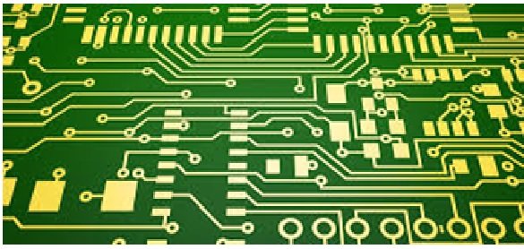
Figure 1 A very Simple printed circuit boards
Types of Printed Circuit Boards
Here we have dived printed circuit boards in seven types and are explained with their manufacturing metrical.
Single-Layer PCBs: Single layer PCB is basically a one-sided PCB means it is coated form one side with a base material. Copper has been used as a base material because it is good conductor and have low resistivity. It is easy to design and manufacture. So, various components could be easily installed and sold on it therefore it is less costly and so much simple. It has been used in various electronic devices such as cameras, calculators, radios, printers, power supplies and solid state drives etc. Its diagram is shown in figure 2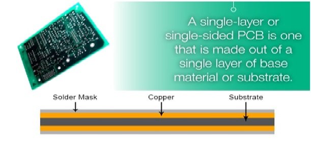
Figure 2 Single Layer PCBs
Double-Layer PCBs: Double layer or double-sided PCB is coated on both sides from a base conductive material like copper and in this type a thin layer of copper is used. It is relatively less thin as compared to single sided PCB. For making holes it is drilled though out means a single hole is enough for both sides. Components on both sides are connect with each other through a small wire or leads that is adjust through out the single hole. This type of PCB is mostly used in that type of industrial application which required an intermediate level of circuit complexity such as LED lighting, HVAC system, power supplies, automotive dashboards and vending machines etc. Its diagram is shown is figure 3
Figure 3 Double-Layer printed circuit boards
Multi-Layer PCBs: Multi-layer PCB composed of a series of three layers of PCB or composed of two or three double layered PCBs. These layers are separated with other with the help of high quality insulating material. This material does not heat up when any component is heat up during operation.50 layers thick PCB have been used till now but, when so many PCB sheets are connected together, then a so much thick layer PCB is made. This type of PCB makes the circuit so much complex therefore it is mostly used in complicated electronics tasks such as in data storage device, satellite system, PS technology and in medical equipment. Its diagram is shown in figure 4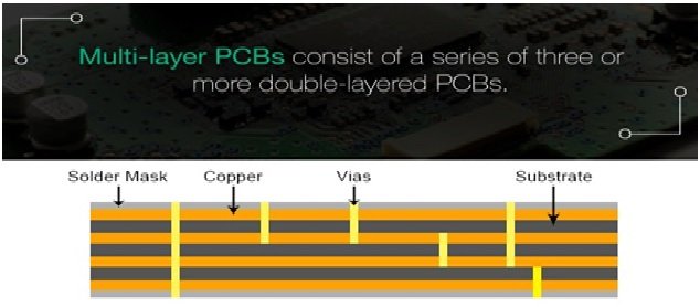
Figure 4 Multi-layer PCBs
Rigid PCBs: Rigid PCBs are almost same as other type of PCBs but only difference is that, these are made out a solid substrate material which save the board from twisting. Its most famous example is computer mother board. Computer mother board is the multi-layer PCB which do many works simultaneously such as same time it communicates with CPU, RAM and GPU. Rigid PCBs could be single-layer, double-layer or multi-layers. Its diagram is shown in figure 5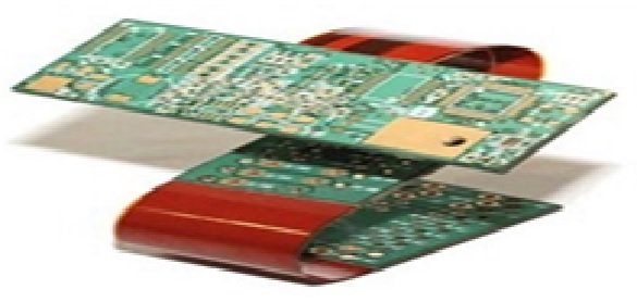
Figure 5 Rigid PCBs
Flexible PCBs: Flexible PCBs are differing from rigid PCBs because these are made with soft substrate material such as fiberglass. Fiberglass is a material that can easily move and flex like a plastic. In this type, because circuit is printed on a soft fiberglass material therefor its fabrication is costly as compared to other type of PCBs, but it still has so many advantages as compared to other type of PCBs. Because it is environmentally hazards therefore these mostly used at that places which are water proof, shock proof and corrosion resistance. Its diagram is shown in figure 6 
Figure 6 Flexible PCBs
Flex-rigid PCBs: Flex-rigid PCBs have both characteristics such as these are flexible as well as with rigid.so these are so much best as compared to above ones. These PCBs could be single-layer, double-layer or multi-layer. When rigid and flexible PCBs are combined together to get a flex-rigid PCB then it reduces weigh and overall size of the board. These are mostly used in cell phones, digital cameras and automobiles. Its diagram is shown in figure 7
Figure 7 Flex-rigid PCBs
High Frequency PCBs: High frequency PCBs are almost as same as other ones PCBs only differ is in its construction because these are designed for high frequency almost in giga hazards. These PCBs are made with a material such as glass-reinforced epoxy laminate, polyphenylene oxide (PPOI and Teflon etc. when the user designed high frequency PCBs, then he should be keep in mind so many aspects such as dielectric constant, loss, PCB connector and dielectric thickness etc. These PCB are used in high frequency equipment as spectrum analyzer and in antenna design etc.
Different Advantages of Using a Printed Circuit Boards
Printed circuit board is very important part of the modern electronic devices and it has so many advantages, some which are we discussed here.
- Because electronic devices consist of so many electronic components, if we joint them with a wire then we can’t joint them on small size board and large number of wires are required to joint them, but printed circuit board has solved this problem. It has compact size of a circuit and save the wires.
- In case of a damage the circuit then it is not so much easy to diagnose the fault and repair the circuit, but printed circuit board has made the easy to diagnose the fault and respire it.
- Conventional methods, that are used to connect the circuit takes so much time to make the circuit, but printed circuit board has save this time.
- Because all the connections are making automatically through software therefore there is no chances of loose connection or short circuit.
- Because printed circuit boards are designed with proper lay out therefore their electronic circuit give noise.
- Printed circuit boards are less costly, more reliable and more efficient
Since I’m not familiar with printed circuit boards, I decided to look them out since my nephew has been asking questions about them. It’s a good thing I found your blog because you mentioned that since copper rails are used instead of real wires, it might have several components. I’ll be sure to let him know about this and suggest that he look into PCB manufacturers who can assist us in obtaining one in the event that he needs one for projects. Thanks for sharing!