In this tutorial, we will learn to interface MPU6050 gyroscope and accelerometer sensor with TM4C123G Tiva C microcontroller. MPU6050 sensor module has 6-axis motion tracking sensors integrated inside the single-chip such as 3-axis measurement for gyroscope and 3-axis measurement for acceleration. Hence, we can use this sensor to measure acceleration, velocity, displacement, and many other electro-mechanical features.
This sensor provides data output over I2C bus protocol. That means in order to read sensor values with the help of TM4C123G Tiva microcontroller, we will use the I2C module of TM4C123G microcontroller. This microcontroller has 4 built-in I2C modules.
Pre-requisities:
- How to Download and Install Keil uVision for ARM and 8051
- Getting started with Keil uVision: Write your first Program for Tiva LaunchPad
Recommended Components
The following components are used in this project or are helpful for getting started with TM4C123 Tiva C LaunchPad development.
| Component | How it’s used in this project | Buy on Amazon |
|---|---|---|
| TM4C123G Tiva C LaunchPad | The main board reading the sensor over I2C | Check Price |
| Micro USB Cable | Programs and powers the board via onboard ICDI | Check Price |
| MPU6050 Module | Gyroscope and accelerometer sensor read over I2C | Check Price |
| Breadboard | Holds the MPU6050 module for the wiring | Check Price |
| Jumper Wires | Connect SDA, SCL, VCC and GND to the board | Check Price |
As an Amazon Associate we earn from qualifying purchases. Prices and availability are accurate as of the date/time indicated and are subject to change.
MPU6050 Sensor Introduction
MPU6050 gyroscope and accelerometer sensor consist of a digital motion sensor that performs all complex processing and computations and provides sensor data output to other MCUs over I2C communication. It has been widely adopted and become very popular in smartphones and tablets for gesture control applications. Moreover, it has also been deployed in advanced gaming, Head Gesture Controlled Wheelchair for Quadriplegic Patients, augmented reality, motion tracking systems, and panoramic pictures taking.
Features
First, let’s discuss some important features of the MPU6050 sensor module. It has a built-in I2C sensor bus which is used to provide gyroscope, accelerometer, and temperature sensor data to other devices such as microcontrollers. This sensor module has onboard pull-up resistors. Therefore, we do not need to connect external pull resistors which are a requirement for the I2C bus interface. Some other features are:
- User Programmable gyroscope and accelerometer with the help of 16-bit analog to digital converter.
- 1024 Byte FIFO buffer to provide data to the connected microcontroller in high speed and enters the low power mode afterwards.
- Built-in temperature sensor.
Pinout
The figure below shows the pinout diagram of the Gyroscope and accelerometer sensor. It consists of 8 pins. But to interface it with any microcontroller, we only need its four pins such as VCC, GND, SDA and SCL pins.
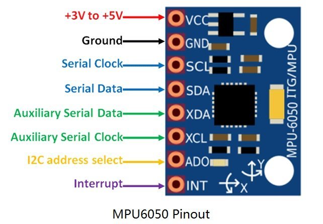
Pins SDA and SCL are used to interface it with microcontroller or microprocessor through I2C communication protocol. Similarly, we will be using I2C modules of TM4C123G Tiva C launchpad to read data from MPU6050 data registers.
Connect GND pin with the ground connection of microcontroller and Vcc pin with 3.3 volt power supply. But pins of MPU6050 can withstand 5 volts also.
MPU6050 Interface with TM4C123G Tiva Circuit Diagram
Now make the connections with MPU6050 and TM4C123G Tiva C microcontroller according to this circuit diagram.

As we mentioned earlier, this MPU6050 sensor module provides data through I2C communication. Hence, we will use the I2C3 module of TM4C123 microcontroller and we will connect the I2C3 module of TM4C123 microcontroller with SCL and SDA pins of MPU6050 sensor as shown in figure above.
In this example code of TM4C123 Tiva C microcontroller, we will print measured sensor values such as gyro and acceleration on the hyper terminal of the computer using USB to serial converter. We will use the UART module of Tiva Launchpad to transfer data to the computer. Therefore, also connect an FTDI (USB-Serial Converter) with PD0 and PDD1 pins of TM4C123 Launchpad.
Code MPU6050 with Tiva C Launchpad
These function prototypes are for UART communication which we have developed in the last tutorial. Therefore, we will not discuss about UART functions.
void uart5_init(void);
void UART5_Transmitter(unsigned char data);
void printstring(char *str);
For more information about them, you can read this article:
As we mentioned earlier, TM4C123 microcontroller reads data from MPU6050 over I2C communication. We use the I2C driver of TM4C123 which we developed in the last tutorial on I2C Communication.
void I2C3_Init(void);
char I2C3_Wr(int slaveAddr, char memAddr, char data);
char I2C3_Rd(int slaveAddr, char memAddr, int byteCount, char* data);
This MPU6050 code for TM4C123 Tiva microcontrollers reads the gyroscope and accelerometer axis data through I2C communication and sends data to computer through UART communication.
#include "TM4C123GH6PM.h"
#include <stdlib.h>
#include <string.h>
#include <stdio.h>
#define XG_OFFS_TC          0x00
#define YG_OFFS_TC          0x01
#define ZG_OFFS_TC          0x02
#define X_FINE_GAIN         0x03
#define Y_FINE_GAIN         0x04
#define Z_FINE_GAIN         0x05
#define XA_OFFS_H           0x06
#define XA_OFFS_L_TC        0x07
#define YA_OFFS_H           0x08
#define YA_OFFS_L_TC        0x09
#define ZA_OFFS_H           0x0A
#define ZA_OFFS_L_TC        0x0B
#define XG_OFFS_USRH        0x13
#define XG_OFFS_USRL        0x14
#define YG_OFFS_USRH        0x15
#define YG_OFFS_USRL        0x16
#define ZG_OFFS_USRH        0x17
#define ZG_OFFS_USRL        0x18
#define SMPLRT_DIV          0x19
#define CONFIG              0x1A
#define GYRO_CONFIG         0x1B
#define ACCEL_CONFIG        0x1C
#define FF_THR              0x1D
#define FF_DUR              0x1E
#define MOT_THR             0x1F
#define MOT_DUR             0x20
#define ZRMOT_THR           0x21
#define ZRMOT_DUR           0x22
#define FIFO_EN             0x23
#define I2C_MST_CTRL        0x24
#define I2C_SLV0_ADDR       0x25
#define I2C_SLV0_REG        0x26
#define I2C_SLV0_CTRL       0x27
#define I2C_SLV1_ADDR       0x28
#define I2C_SLV1_REG        0x29
#define I2C_SLV1_CTRL       0x2A
#define I2C_SLV2_ADDR       0x2B
#define I2C_SLV2_REG        0x2C
#define I2C_SLV2_CTRL       0x2D
#define I2C_SLV3_ADDR       0x2E
#define I2C_SLV3_REG        0x2F
#define I2C_SLV3_CTRL       0x30
#define I2C_SLV4_ADDR       0x31
#define I2C_SLV4_REG        0x32
#define I2C_SLV4_DO         0x33
#define I2C_SLV4_CTRL       0x34
#define I2C_SLV4_DI         0x35
#define I2C_MST_STATUS      0x36
#define INT_PIN_CFG         0x37
#define INT_ENABLE          0x38
#define DMP_INT_STATUS      0x39
#define INT_STATUS          0x3A
#define ACCEL_XOUT_H        0x3B
#define ACCEL_XOUT_L        0x3C
#define ACCEL_YOUT_H        0x3D
#define ACCEL_YOUT_L        0x3E
#define ACCEL_ZOUT_H        0x3F
#define ACCEL_ZOUT_L        0x40
#define TEMP_OUT_H          0x41
#define TEMP_OUT_L          0x42
#define GYRO_XOUT_H         0x43
#define GYRO_XOUT_L         0x44
#define GYRO_YOUT_H         0x45
#define GYRO_YOUT_L         0x46
#define GYRO_ZOUT_H         0x47
#define GYRO_ZOUT_L         0x48
#define EXT_SENS_DATA_00    0x49
#define EXT_SENS_DATA_01    0x4A
#define EXT_SENS_DATA_02    0x4B
#define EXT_SENS_DATA_03    0x4C
#define EXT_SENS_DATA_04    0x4D
#define EXT_SENS_DATA_05    0x4E
#define EXT_SENS_DATA_06    0x4F
#define EXT_SENS_DATA_07    0x50
#define EXT_SENS_DATA_08    0x51
#define EXT_SENS_DATA_09    0x52
#define EXT_SENS_DATA_10    0x53
#define EXT_SENS_DATA_11    0x54
#define EXT_SENS_DATA_12    0x55
#define EXT_SENS_DATA_13    0x56
#define EXT_SENS_DATA_14    0x57
#define EXT_SENS_DATA_15    0x58
#define EXT_SENS_DATA_16    0x59
#define EXT_SENS_DATA_17    0x5A
#define EXT_SENS_DATA_18    0x5B
#define EXT_SENS_DATA_19    0x5C
#define EXT_SENS_DATA_20    0x5D
#define EXT_SENS_DATA_21    0x5E
#define EXT_SENS_DATA_22    0x5F
#define EXT_SENS_DATA_23    0x60
#define MOT_DETECT_STATUS   0x61
#define I2C_SLV0_DO         0x63
#define I2C_SLV1_DO         0x64
#define I2C_SLV2_DO         0x65
#define I2C_SLV3_DO         0x66
#define I2C_MST_DELAY_CTRL  0x67
#define SIGNAL_PATH_RESET   0x68
#define MOT_DETECT_CTRL     0x69
#define USER_CTRL           0x6A
#define PWR_MGMT_1          0x6B
#define PWR_MGMT_2          0x6C
#define BANK_SEL            0x6D
#define MEM_START_ADDR      0x6E
#define MEM_R_W             0x6F
#define DMP_CFG_1           0x70
#define DMP_CFG_2           0x71
#define FIFO_COUNTH         0x72
#define FIFO_COUNTL         0x73
#define FIFO_R_W            0x74
#define WHO_AM_I            0x75
void I2C3_Init(void);
char I2C3_Wr(int slaveAddr, char memAddr, char data);
char I2C3_Rd(int slaveAddr, char memAddr, int byteCount, char* data);
void Delay(unsigned long counter);
void uart5_init(void);
void UART5_Transmitter(unsigned char data);
void printstring(char *str);
void MPU6050_Init(void);

char msg[20];
int main(void)
{
  int  accX, accY, accZ, GyroX, GyroY, GyroZ, Temper;
	float AX, AY, AZ, t, GX, GY, GZ;
	char sensordata[14];
	I2C3_Init();
	Delay(1000);
	MPU6050_Init();
	Delay(1000);
  uart5_init();
	while(1)
	{
 I2C3_Rd(0x68,ACCEL_XOUT_H, 14, sensordata);
 accX = (int) ( (sensordata[0] << 8 ) |sensordata[1] );
 accY = (int) ( (sensordata[2] << 8 ) |sensordata[3] );
 accZ = (int) ( (sensordata[4] << 8 ) |sensordata[5] );
 Temper = (int) ( (sensordata[6] << 8 ) |sensordata[7] );
 GyroX = (int) ( (sensordata[8] << 8 ) |sensordata[9] );
 GyroY = (int) ( (sensordata[10] << 8 ) |sensordata[11] );
 GyroZ = (int) ( (sensordata[12] << 8 ) |sensordata[13] );


   // Convert The Readings
  AX = (float)accX/16384.0;
  AY = (float)accY/16384.0;
  AZ = (float)accZ/16384.0;
  GX = (float)GyroX/131.0;
  GY = (float)GyroX/131.0;
  GZ = (float)GyroX/131.0;
  t = ((float)Temper/340.00)+36.53;
     sprintf(msg,"Gx = %.2f \t",GX);
     printstring(msg);
		 sprintf(msg,"Gy = %.2f \t",GY);
     printstring(msg);
		 sprintf(msg,"Gz  = %.2f \t",GZ);
     printstring(msg);
		 sprintf(msg,"Ax  = %.2f \t",AX);
     printstring(msg);
		 sprintf(msg,"Ay  = %.2f \t",AY);
     printstring(msg);
		 sprintf(msg,"Ax  = %.2f \r\n",AZ);
     printstring(msg);

     Delay(1000);
	}
}

void MPU6050_Init(void)
{
 I2C3_Wr(0x68,SMPLRT_DIV, 0x07);
 I2C3_Wr(0x68,PWR_MGMT_1,  0x01);
 I2C3_Wr(0x68,CONFIG, 0x00);
 I2C3_Wr(0x68,ACCEL_CONFIG,0x00);
 I2C3_Wr(0x68,GYRO_CONFIG,0x18);
 I2C3_Wr(0x68,INT_ENABLE, 0x01);

}

void uart5_init(void)
{

	  SYSCTL->RCGCUART |= 0x20;  /* enable clock to UART5 */
    SYSCTL->RCGCGPIO |= 0x10;  /* enable clock to PORTE for PE4/Rx and RE5/Tx */
    Delay(1);
    /* UART0 initialization */
    UART5->CTL = 0;         /* UART5 module disbable */
    UART5->IBRD = 104;      /* for 9600 baud rate, integer = 104 */
    UART5->FBRD = 11;       /* for 9600 baud rate, fractional = 11*/
    UART5->CC = 0;          /*select system clock*/
    UART5->LCRH = 0x60;     /* data lenght 8-bit, not parity bit, no FIFO */
    UART5->CTL = 0x301;     /* Enable UART5 module, Rx and Tx */

    /* UART5 TX5 and RX5 use PE4 and PE5. Configure them digital and enable alternate function */
    GPIOE->DEN = 0x30;      /* set PE4 and PE5 as digital */
    GPIOE->AFSEL = 0x30;    /* Use PE4,PE5 alternate function */
    GPIOE->AMSEL = 0;    /* Turn off analg function*/
    GPIOE->PCTL = 0x00110000;     /* configure PE4 and PE5 for UART */

}
void I2C3_Init(void)
{
SYSCTL->RCGCGPIO  |= 0x00000008 ; // Enable the clock for port D
SYSCTL->RCGCI2C   |= 0x00000008 ; // Enable the clock for I2C 3
GPIOD->DEN |= 0x03; // Assert DEN for port D
// Configure Port D pins 0 and 1 as I2C 3
GPIOD->AFSEL |= 0x00000003 ;
GPIOD->PCTL |= 0x00000033 ;
GPIOD->ODR |= 0x00000002 ; // SDA (PD1 ) pin as open darin
I2C3->MCR  = 0x0010 ; // Enable I2C 3 master function
/* Configure I2C 3 clock frequency
(1 + TIME_PERIOD ) = SYS_CLK /(2*
( SCL_LP + SCL_HP ) * I2C_CLK_Freq )
TIME_PERIOD = 16 ,000 ,000/(2(6+4) *100000) - 1 = 7 */
I2C3->MTPR  = 0x07 ;
}

/* Wait until I2C master is not busy and return error code */
/* If there is no error, return 0 */
static int I2C_wait_till_done(void)
{
    while(I2C3->MCS & 1);   /* wait until I2C master is not busy */
    return I2C3->MCS & 0xE; /* return I2C error code */
}

/* Write one byte only */
/* byte write: S-(saddr+w)-ACK-maddr-ACK-data-ACK-P */
char I2C3_Wr(int slaveAddr, char memAddr, char data)
{

    char error;

    /* send slave address and starting address */
    I2C3->MSA = slaveAddr << 1;
    I2C3->MDR = memAddr;
    I2C3->MCS = 3;                      /* S-(saddr+w)-ACK-maddr-ACK */

    error = I2C_wait_till_done();       /* wait until write is complete */
    if (error) return error;

    /* send data */
    I2C3->MDR = data;
    I2C3->MCS = 5;                      /* -data-ACK-P */
    error = I2C_wait_till_done();       /* wait until write is complete */
    while(I2C3->MCS & 0x40);            /* wait until bus is not busy */
    error = I2C3->MCS & 0xE;
    if (error) return error;

    return 0;       /* no error */
}
char I2C3_Rd(int slaveAddr, char memAddr, int byteCount, char* data)
{
     char error;

    if (byteCount <= 0)
        return -1;         /* no read was performed */

    /* send slave address and starting address */
    I2C3->MSA = slaveAddr << 1;
    I2C3->MDR = memAddr;
    I2C3->MCS = 3;       /* S-(saddr+w)-ACK-maddr-ACK */
    error = I2C_wait_till_done();
    if (error)
        return error;

    /* to change bus from write to read, send restart with slave addr */
    I2C3->MSA = (slaveAddr << 1) + 1;   /* restart: -R-(saddr+r)-ACK */

    if (byteCount == 1)             /* if last byte, don't ack */
        I2C3->MCS = 7;              /* -data-NACK-P */
    else                            /* else ack */
        I2C3->MCS = 0xB;            /* -data-ACK- */
    error = I2C_wait_till_done();
    if (error) return error;

    *data++ = I2C3->MDR;            /* store the data received */

    if (--byteCount == 0)           /* if single byte read, done */
    {
        while(I2C3->MCS & 0x40);    /* wait until bus is not busy */
        return 0;       /* no error */
    }

    /* read the rest of the bytes */
    while (byteCount > 1)
    {
        I2C3->MCS = 9;              /* -data-ACK- */
        error = I2C_wait_till_done();
        if (error) return error;
        byteCount--;
        *data++ = I2C3->MDR;        /* store data received */
    }

    I2C3->MCS = 5;                  /* -data-NACK-P */
    error = I2C_wait_till_done();
    *data = I2C3->MDR;              /* store data received */
    while(I2C3->MCS & 0x40);        /* wait until bus is not busy */

    return 0;       /* no error */
}

void UART5_Transmitter(unsigned char data)
{
    while((UART5->FR & (1<<5)) != 0); /* wait until Tx buffer not full */
    UART5->DR = data;                  /* before giving it another byte */
}

void printstring(char *str)
{
  while(*str)
	{
		UART5_Transmitter(*(str++));
	}
}
void Delay(unsigned long counter)
{
	unsigned long i = 0;

	for(i=0; i< counter*10000; i++);
}
Video Demo
Now create a project in Keil uvision and upload this code to TM4C123G Tiva Launchpad. After that make the connection according to the above-given interfacing circuit.
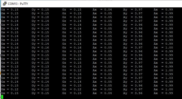
This video demo shows the output of MPU6050 sensor values such as gyro and acceleration.
How code works
In this example code, TM4C123G microcontroller is configured as a master and MPU6050 as a slave. Hence, TM4123G microcontroller will initiate the
MPU6050 Register Map
First we define the names of MPU6050 addresses using “#define” preprocessing directive. We will use these register addresses to initialize sensor and to read gyro and acceleration outputs from their respective registers by using their addresses.
#include <stdio.h>
#define XG_OFFS_TC          0x00
#define YG_OFFS_TC          0x01
#define ZG_OFFS_TC          0x02
#define X_FINE_GAIN         0x03
#define Y_FINE_GAIN         0x04
#define Z_FINE_GAIN         0x05
#define XA_OFFS_H           0x06
#define XA_OFFS_L_TC        0x07
#define YA_OFFS_H           0x08
#define YA_OFFS_L_TC        0x09
#define ZA_OFFS_H           0x0A
#define ZA_OFFS_L_TC        0x0B
#define XG_OFFS_USRH        0x13
#define XG_OFFS_USRL        0x14
#define YG_OFFS_USRH        0x15
#define YG_OFFS_USRL        0x16
#define ZG_OFFS_USRH        0x17
#define ZG_OFFS_USRL        0x18
#define SMPLRT_DIV          0x19
#define CONFIG              0x1A
#define GYRO_CONFIG         0x1B
#define ACCEL_CONFIG        0x1C
#define FF_THR              0x1D
#define FF_DUR              0x1E
#define MOT_THR             0x1F
#define MOT_DUR             0x20
#define ZRMOT_THR           0x21
#define ZRMOT_DUR           0x22
#define FIFO_EN             0x23
#define I2C_MST_CTRL        0x24
#define I2C_SLV0_ADDR       0x25
#define I2C_SLV0_REG        0x26
#define I2C_SLV0_CTRL       0x27
#define I2C_SLV1_ADDR       0x28
#define I2C_SLV1_REG        0x29
#define I2C_SLV1_CTRL       0x2A
#define I2C_SLV2_ADDR       0x2B
#define I2C_SLV2_REG        0x2C
#define I2C_SLV2_CTRL       0x2D
#define I2C_SLV3_ADDR       0x2E
#define I2C_SLV3_REG        0x2F
#define I2C_SLV3_CTRL       0x30
#define I2C_SLV4_ADDR       0x31
#define I2C_SLV4_REG        0x32
#define I2C_SLV4_DO         0x33
#define I2C_SLV4_CTRL       0x34
#define I2C_SLV4_DI         0x35
#define I2C_MST_STATUS      0x36
#define INT_PIN_CFG         0x37
#define INT_ENABLE          0x38
#define DMP_INT_STATUS      0x39
#define INT_STATUS          0x3A
#define ACCEL_XOUT_H        0x3B
#define ACCEL_XOUT_L        0x3C
#define ACCEL_YOUT_H        0x3D
#define ACCEL_YOUT_L        0x3E
#define ACCEL_ZOUT_H        0x3F
#define ACCEL_ZOUT_L        0x40
#define TEMP_OUT_H          0x41
#define TEMP_OUT_L          0x42
#define GYRO_XOUT_H         0x43
#define GYRO_XOUT_L         0x44
#define GYRO_YOUT_H         0x45
#define GYRO_YOUT_L         0x46
#define GYRO_ZOUT_H         0x47
#define GYRO_ZOUT_L         0x48
#define EXT_SENS_DATA_00    0x49
#define EXT_SENS_DATA_01    0x4A
#define EXT_SENS_DATA_02    0x4B
#define EXT_SENS_DATA_03    0x4C
#define EXT_SENS_DATA_04    0x4D
#define EXT_SENS_DATA_05    0x4E
#define EXT_SENS_DATA_06    0x4F
#define EXT_SENS_DATA_07    0x50
#define EXT_SENS_DATA_08    0x51
#define EXT_SENS_DATA_09    0x52
#define EXT_SENS_DATA_10    0x53
#define EXT_SENS_DATA_11    0x54
#define EXT_SENS_DATA_12    0x55
#define EXT_SENS_DATA_13    0x56
#define EXT_SENS_DATA_14    0x57
#define EXT_SENS_DATA_15    0x58
#define EXT_SENS_DATA_16    0x59
#define EXT_SENS_DATA_17    0x5A
#define EXT_SENS_DATA_18    0x5B
#define EXT_SENS_DATA_19    0x5C
#define EXT_SENS_DATA_20    0x5D
#define EXT_SENS_DATA_21    0x5E
#define EXT_SENS_DATA_22    0x5F
#define EXT_SENS_DATA_23    0x60
#define MOT_DETECT_STATUS   0x61
#define I2C_SLV0_DO         0x63
#define I2C_SLV1_DO         0x64
#define I2C_SLV2_DO         0x65
#define I2C_SLV3_DO         0x66
#define I2C_MST_DELAY_CTRL  0x67
#define SIGNAL_PATH_RESET   0x68
#define MOT_DETECT_CTRL     0x69
#define USER_CTRL           0x6A
#define PWR_MGMT_1          0x6B
#define PWR_MGMT_2          0x6C
#define BANK_SEL            0x6D
#define MEM_START_ADDR      0x6E
#define MEM_R_W             0x6F
#define DMP_CFG_1           0x70
#define DMP_CFG_2           0x71
#define FIFO_COUNTH         0x72
#define FIFO_COUNTL         0x73
#define FIFO_R_W            0x74
#define WHO_AM_I            0x75
MPU6050 Initialization Function
This void MPU6050_Init(void) function initializes the sensor by writing values to respective registers of MPU6050 over the I2C bus. I2C3_Wr() routine writes sets the registers with the values.
First argument to I2C3_Wr() is a address of MPU6050 which is used as a salve device. The second argument is a address of register inside the sensor whose value we want to set or update and the last argument is the actual value which we want to write to the register address.
void MPU6050_Init(void)
{
 //set the sampling rate to 1kHz
 I2C3_Wr(0x68,SMPLRT_DIV, 0x07);
//uses clock of gyro with PLL
 I2C3_Wr(0x68,PWR_MGMT_1,  0x01);
// disable external input and use highest bandwidth frequency
 I2C3_Wr(0x68,CONFIG, 0x00);
// select accelerometer full scale range ±2g
 I2C3_Wr(0x68,ACCEL_CONFIG,0x00);
// select gyro full scale range ±2g
 I2C3_Wr(0x68,GYRO_CONFIG,0x18);
//Enable internal interrupt when data ready
 I2C3_Wr(0x68,INT_ENABLE, 0x01);

}
Reading Acceleration and Gyro values from MPU6050
This implementation reads 3-axis values of acceleration and gyro. After that, it send values to computer through UART port.
I2C3_Rd(0x68,ACCEL_XOUT_H, 14, sensordata);
 accX = (int) ( (sensordata[0] << 8 ) |sensordata[1] );
 accY = (int) ( (sensordata[2] << 8 ) |sensordata[3] );
 accZ = (int) ( (sensordata[4] << 8 ) |sensordata[5] );
 Temper = (int) ( (sensordata[6] << 8 ) |sensordata[7] );
 GyroX = (int) ( (sensordata[8] << 8 ) |sensordata[9] );
 GyroY = (int) ( (sensordata[10] << 8 ) |sensordata[11] );
 GyroZ = (int) ( (sensordata[12] << 8 ) |sensordata[13] );


   // Convert The Readings
  AX = (float)accX/16384.0;
  AY = (float)accY/16384.0;
  AZ = (float)accZ/16384.0;
  GX = (float)GyroX/131.0;
  GY = (float)GyroX/131.0;
  GZ = (float)GyroX/131.0;
  t = ((float)Temper/340.00)+36.53;
     sprintf(msg,"Gx = %.2f \t",GX);
     printstring(msg);
		 sprintf(msg,"Gy = %.2f \t",GY);
     printstring(msg);
		 sprintf(msg,"Gz  = %.2f \t",GZ);
     printstring(msg);
		 sprintf(msg,"Ax  = %.2f \t",AX);
     printstring(msg);
		 sprintf(msg,"Ay  = %.2f \t",AY);
     printstring(msg);
		 sprintf(msg,"Ax  = %.2f \r\n",AZ);
     printstring(msg);
     Delay(1000);
Conclusion
In conclusion, interfacing the MPU6050 gyroscope and accelerometer sensor with the TM4C123G Tiva C microcontroller offers a robust solution for measuring motion and orientation. Through I2C communication, the MPU6050 can efficiently relay sensor data, which can then be processed and displayed using the Tiva C microcontroller’s UART module. This setup is particularly useful in applications requiring precise motion tracking, such as in gesture-controlled devices and augmented reality systems. By following this tutorial, you can effectively harness the capabilities of the MPU6050 with the TM4C123G for a wide range of electro-mechanical projects.
We have similar guides with other Microcontrollers:
- ESP32 with MPU6050 Accelerometer, Gyroscope, and Temperature Sensor ( Arduino IDE)
- MPU6050 Sensor Module Interfacing with Pic Microcontroller
You may also like to read:
Hello friend I just subscribed
Can you explain me circuit diagram of this experiment?
we will connect PD0 and PD1 with gyroscope . but i didnt understand the connection of FTDI….
I didnt undersatnd how we connect FTDI with tiva. KINDLY edify me
Thanks
FTDI connections are also given in the schematic shown in the article.
How does the program read data from the gyroscope?
can you explain “I2C3_Rd(0x68,ACCEL_XOUT_H, 14, sensordata);” ?
Why did you choose that slave address and memory address?
Can you explain why you chose the bits and shifted it and compared it in the following lines?
Also, why is the clock not enabled for UART5 in the code? I thought it should be
UART5->CC = 1; /*select system clock*/
Can you explain how you are reading from Accel and Gyro values from the MPU6050?
How do you choose which slave address and memory address to read from?
what does the bit shift operators do?
UART5->CC = 0; does this mean that the clock is not enabled?
You can refer to datasheet of MPU6050 for register addresses to be read.
hi!
It works well, but please use these types for outputs:
int16_t accX, accY, accZ, GyroX, GyroY, GyroZ, Temper;
uint8_t sensordata[14];
Otherwise, I had a problem with the accelerometer data (type conversion error)
Hello, I have a problem, terminal shows just zeros. Connection is ok. I tried MPU6050 on RP2040, and its working.
Could you help me, please?
I am facing same problem, can u help me if u got how to resolve