Pc controlled stepper motor system using pic microcontroller is a system in which stepper motor position or angle is controlled through desk top computer or any laptop. Currently, stepper motor has been used in several applications such as in antennas, telescope, hard disk drives, toys and in robotic industry. If we see its applications then its driver circuit is also so much important for its precise movement. Lot of companies or peoples have been working on its driver circuit, some have offered the driver circuit but their driver circuit cost is so much high as well as not so much reliable and efficient.
Here we have offered a system that is called a pc controlled stepper motor system. Which is designed with the help of pic microcontrollers, USB to UART module, LCD display, desk top computer or lap top and stepper motor. This pc controlled stepper motor system is more reliable, compact, efficient, less costly and tells the motor speed more precisely as compared to other stepper motor driver circuits. This system is powered up with 220V ac and no need of any extra power supply or power adapter and could be used in different applications which are defined above. The block diagram of this system is shown in figure 1 with all their respective components.
Block Diagram of PC Controlled Stepper Motor System Using PIC Microcontroller:
Here is the block diagram of pc controlled stepper motor system using pic microcontroller with all their essentials components,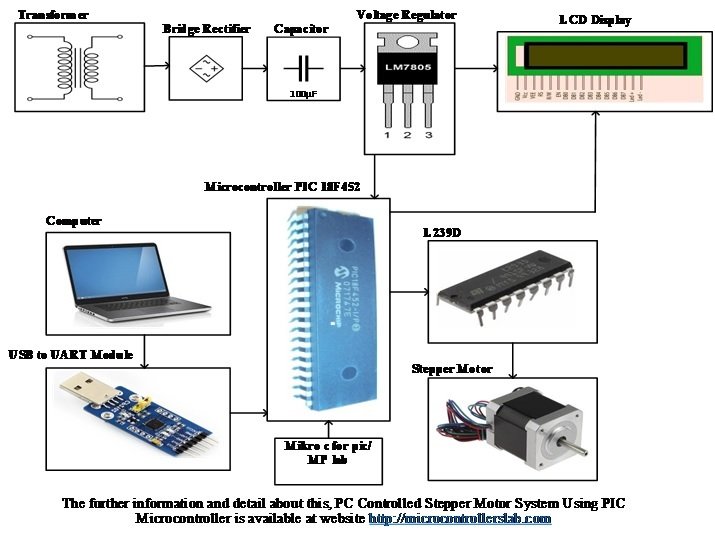
Figure 1 Pc controlled Stepper Motor System Using PIC Microcontroller
Working Principle of Pc Controlled Stepper Motor System Using PIC Microcontroller:
This pc controlled stepper motor system using pic microcontroller works on the principle of delaying angle means its speed is inversely proportional to delaying angle and delaying angle is changed through desk top computer or laptop. Desk top computer or laptop is attached with this system through USB to UART module, which is used for serial communication between laptop to this system and GUI (graphical user interface) tools are used for this serial communication. When delaying angle is changed in laptop then this changing is received by the pic microcontroller in the form of logic signal through USB to UART module.
The microcontroller is 40 pins integrated circuit IC, which is programmed in c language with the help of mikro/c software and accepts the signal in binary logic form. Here it received the logic signal form USB to UART module and then after processing intelligent control of this signal it gives the logic signal to L239D integrated circuit IC. L239D is a 16 pins IC and is used for driving the DC motor. It can easily drive the two dc motors simultaneously in any direction but here we would be drive only one stepper motor, basically it works on the principle of H bridge circuit. Because the dc stepper motor is directly attached with L239D IC therefore we can drive this motor in any direction.
Code of PC controlled stepper motor
The speed of this motor could be also increased or decreased by changing the duty ratio or delaying angle form user computer or lap top. When delaying angle is increased then motor speed is decreased and when delaying angle is decreased then motor speed is increased. This whole process is done automatically only by changing the is delaying angle form user computer or lap top. LCD display is also available in this system for displaying the motor speed and its direction. This LCD display shows the motor speed in RPM (revolution per minutes) This system mostly consists of electronics components which are powered up with 5V dc supply by using the voltage regulator.