Are you a student working on an Arduino-based project? Are you curious about how to interface a piezoelectric sensor with an Arduino? Look no further! In this article, we will explore piezoelectric sensors and explore their applications. We will discuss what a piezoelectric sensor is, how it works, and most importantly, how to connect and program it with an Arduino Uno R3. Whether you are new to Arduino or an experienced enthusiast, this comprehensive guide will equip you with the knowledge and skills to successfully integrate a piezoelectric sensor into your project.

What is a Piezoelectric Sensor?
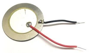
Piezoelectric sensors are basically transducers that convert stress applied to them into electrical energy. They simply use the principle of energy conversion from one form to another. In the case of piezoelectric sensors, they convert physical stress into electrical energy. Stress can be in the form of force, pressure, acceleration, or touch potential. These are all types of stresses that piezoelectric sensors can convert into electrical signals.
These sensors convert mechanical energy, such as pressure or vibration, into an electrical voltage. It is built using materials that exhibit the piezoelectric effect, which is the ability of certain crystals or ceramics to generate an electric charge when subjected to mechanical stress. Conversely, these materials can also deform or vibrate when an electrical voltage is applied across them. This unique behavior allows piezoelectric sensors to efficiently measure changes in mechanical variables and translate them into electrical signals.
Application
You will see enormous applications of piezoelectric transducers around you in daily usage things. Some of the major application of this sensor is given below :
- Motion detection
- Door knock sensor
- Acceleration measurement system
- force measurement system
- pressure measurement system
- Microphone uses sound pressure to convert it into electrical form.
- lighters for cigarette
- testing of high-voltage equipment’s
- And there are thousands of applications of piezoelectric sensor.
How Piezoelectric Sensor work?
The core principle of a piezoelectric sensor involves the arrangement of piezoelectric materials in such a way that they can sense and respond to external forces. When pressure or vibration is applied to the sensor, the piezoelectric material undergoes deformation, leading to the generation of an electric charge. This charge can then be measured and interpreted to determine the magnitude and nature of the applied mechanical stimulus.
Whenever stress is applied to piezoelectric sensors, a potential difference of the same magnitude of force is produced across the piezoelectric transducer. This allows it to easily convert mechanical energy into electrical energy. Piezoelectric sensors produce an analog output voltage. If you would like to understand the internal construction and workings of this sensor, I recommend searching for it on Google. It is not possible for me to cover all the details in one topic. However, if you understand the basic workings of a piezoelectric transducer, it should be sufficient for you to use in your project.
Piezoelectric Sensor Interfacing with Arduino
Piezoelectric sensors produce an analog voltage at the output. To interface this sensor with Arduino or any other microcontroller, you should know how to measure analog voltage.
If you don’t know how to measure analog voltage using Arduino, we suggest you read the following article first: Arduino Analog Voltage Measurement Guide. This guide will help you properly understand the process of interfacing piezoelectric sensors with Arduino.
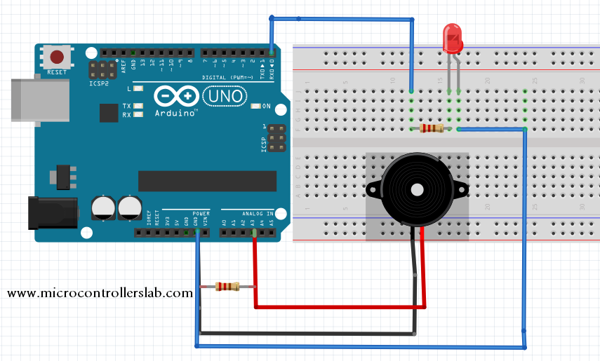
The diagram below shows the hardware connections of a piezoelectric sensor interfacing with an Arduino. Piezoelectric sensors have two output pins: one has a positive potential, and the other has a negative potential (ground). The positive potential pin is connected to pin 3 analog channel of the Arduino, and the negative potential pin is connected to ground. A resistor of 2 megaohms is connected between them for protection purposes. An LED is connected to pin zero to check the working of the sensor’s output.
Code
The code given below is written using Arduino IDE:
int sensorOutput = 4; // The analog pin connected to the sensor
int ledOutput = 13;  // Pin connected to LED (changed from 0)
int THRESHOLD = 100;

void setup()
{
  pinMode(ledOutput, OUTPUT); // Declare LED-connected pin as output
}

void loop()
{
  int value = analogRead(sensorOutput); // Read analog voltage from sensor
  if (value >= THRESHOLD) // Check voltage level from sensor
  {
    digitalWrite(ledOutput, HIGH);
    delay(100); // To make the LED visible
  }
  else
  {
    digitalWrite(ledOutput, LOW);
  }
}
How Does Code Work?
Here is an explanation of the code line by line with code blocks for each line:
int sensorOutput = 4; // The analog pin connected to the sensorThis line declares a variable sensorOutput of type integer and assigns it the value of 4. This variable represents the analog pin connected to the piezoelectric sensor.
int ledOutput = 13; // Pin connected to LED (changed from 0)This line declares a variable ledOutput of type integer and assigns it the value of 13. This variable represents the digital pin connected to an LED. Note that in the original code, the pin was changed from 0 to 13.
int THRESHOLD = 100;This line declares a variable THRESHOLD of type integer and assigns it the value of 100. This variable represents the threshold value that the analog voltage from the sensor needs to surpass in order to turn on the LED.
void setup()
{
      pinMode(ledOutput, OUTPUT); // Declare LED-connected pin as output
}
This setup() function is a special function in Arduino that runs once when the board starts up. In this case, it sets the ledOutput pin as an output, indicating that it will be used to control the LED.
void loop()
 {
 int value = analogRead(sensorOutput); // Read analog voltage from sensor
 if (value >= THRESHOLD) // Check voltage level from sensor
 {
 digitalWrite(ledOutput, HIGH);
 delay(100); // To make the LED visible
 }
 else
 {
 digitalWrite(ledOutput, LOW);
 }
 }
This loop() function is another special function in Arduino that runs repeatedly after the setup() function. In this case, it reads the analog voltage from the sensorOutput pin using the analogRead() function and assigns the value to the value variable.
Then, it checks if the value is greater than or equal to the THRESHOLD value. If it is, it turns on the LED by setting the ledOutput pin to HIGH using the digitalWrite() function. It also adds a delay of 100 milliseconds to make the LED visible.
If the value is below the THRESHOLD, it turns off the LED by setting the ledOutput pin to LOW using the digitalWrite() function.
This loop() function keeps repeating these steps, continuously reading the analog voltage from the sensor and controlling the LED based on the voltage level.
Conclusion
In conclusion, piezoelectric sensors are versatile transducers that convert mechanical energy into electrical signals. In this article, we have explored the working principle of piezoelectric sensors, their various applications, and how to interface them with an Arduino Uno R3. By understanding the basic principles and following the provided code example, you can successfully integrate a piezoelectric sensor into your projects. Whether you are a beginner or an experienced enthusiast, this comprehensive guide has equipped you with the knowledge and skills to incorporate piezoelectric sensors into your Arduino-based projects. So, go ahead and explore the possibilities of this fascinating sensor in your next undertaking!
Related content:
- Infrared Sensor Module Interfacing with Arduino – Obstacle Detection
- Interface HC-SR501 PIR Sensor with Arduino
- Light Sensor and Street Light Control using Arduino
- Servo Motor Control and Interfacing with Arduino
- ADXL320 Acceleration Measurement using Arduino
- Reed Switch Interfacing with Arduino – Magnetic Field Detection
- Flame Sensor Interfacing with Arduino for Fire Detection
- Photoresistor Interfacing with Arduino for Light Measurement


Is there a way to use one of these sensors to send a vailable signal to an electronic speed controller to controll how fast the motor goes?
Hi brother Malik,
My name is Yahya I am a student and we have to do a project in Biomedical Engineering. I have sent you an e-mail regarding power generation through walking using a piezoelectric device. I have also sent you a block diagram regarding it.
Would you please check it and could you please give suggestion. I would greatly appreciate it.
Thanks,
Yahya Ahmed
Hi I’m looking to produce a ultrasonic cleaning product and wonder if this code is applicable for both a ultrasonic sensor and transducer as you have talked about both above.
Hi , I am looking for program for piezoelectric signal interfacing with pic16f877a microcontroller…can u please help me….I am in a. Big trouble …
I am looking a very sensitive sensor for accident impart for my project. will this sensor do?
try infrared sensor for accident alert detection system
how to convert that voltage into stress vale by using arduino board, what is the program for that,