Light sensor and street light control using Arduino is designed to measure the intensity of light or the amount of light. It automatically controls street lights based on the light intensity detected. In this project, we utilize the Arduino UNO R3 for implementation. A light-dependent resistor is used for light detection. To provide isolation between the Arduino and the 220V AC street light, a relay is incorporated. Detailed explanations of the functionality and working of each component will be provided in the subsequent sections of this article.
Recommended Components
The following components are used in this project or are helpful for building it with the Arduino.
| Component | How it’s used in this project | Buy on Amazon |
|---|---|---|
| Arduino Uno R3 | Reads the light level from the LDR and switches the street light via the relay. | Check Price |
| LDR / photoresistor (light sensor) | Changes resistance with ambient light so the Arduino can tell day from night – the sensing element of this project. | Check Price |
| Relay module | Switches the high-power street light (lamp/LED) on and off under Arduino control. | Check Price |
| 5mm LED | Stands in for the street light to demonstrate the on/off control. | Check Price |
| Breadboard | Holds the LDR, resistor and connections for solderless prototyping. | Check Price |
| Jumper Wires | Connect the LDR voltage divider, relay and LED to the Arduino. | Check Price |
As an Amazon Associate we earn from qualifying purchases. Prices and availability are accurate as of the date/time indicated and are subject to change.
Circuit Diagram
A circuit diagram of a light sensor and street light using Arduino is shown below. Now I will explain each component used in this project.
Light dependent resistor (LDR)
Light Dependent Resistor (LDR) is used to detect changes in light intensity or as a light sensor. An LDR is essentially a variable resistor that changes its resistance with the intensity of light. When the light intensity is high, the LDR has low resistance, and when the light intensity decreases, the LDR offers high resistance. Therefore, there is an inverse relationship between the intensity of light and the resistance of the LDR.
To measure the resistance of an LDR and calculate the intensity of light, we can use the Arduino UNO R3 board, which has six analog-to-digital converter channels. However, these channels can only measure voltage and cannot measure resistance directly. To overcome this, we use signal conditioning by connecting a 10K ohm resistor in series with the LDR and a 5-volt source. This circuit converts the resistance into voltage form, which can then be measured using the analog-to-digital converter of the Arduino. The measured voltage across the LDR can be converted back into resistance using the voltage division formula.
If you are unfamiliar with measuring analog voltage using the analog-to-digital converter of the Arduino UNO R3, I recommend going through a tutorial before proceeding further.
Relay
In this project, a relay is used to provide isolation between low-voltage circuitry and high-voltage circuitry. Arduino is also used to provide a control signal to the relay whenever the intensity of light falls below a certain level. The control signal is generated from pin 13 of Arduino, which is used as an output pin. A transistor is used as a switch here. If you don’t know how to use input or output pins of Arduino UNO R3, please read the following article:
Light Sensor with Arduino
The circuit diagram shown in the image represents a light sensor and street light control system using Arduino. Let’s break down the components and their functions:
- Arduino UNO R3: The Arduino UNO R3 board serves as the main microcontroller in this project. It receives input from the light sensor and controls the street lights based on the detected light intensity.
- Light Dependent Resistor (LDR): The LDR is a sensor that detects changes in the intensity of light. It is connected in series with a 10K ohm resistor and a 5-volt power supply. The resistance of the LDR varies with the intensity of light falling upon it.
- Analog-to-Digital Converter (ADC): The Arduino UNO R3 board has six ADC channels that can measure voltage. In this project, the measured voltage across the LDR is converted into a corresponding resistance value using a voltage divider circuit. This resistance value is then converted into a digital value by the ADC for further processing.
- Relay: The relay is used to provide isolation between the low-voltage circuitry (Arduino) and the high-voltage circuitry (street lights). It acts as a switch that is controlled by the Arduino. When the light intensity falls below a certain level, the Arduino sends a control signal to the relay, which then switches on or off the street lights accordingly.
- Transistor: The transistor acts as a switch between the Arduino and the relay. In this circuit, a transistor is used to amplify the control signal from the Arduino and drive the coil of the relay.
Overall, this circuit diagram showcases how the Arduino, LDR, ADC, relay, and transistor are interconnected to create a light sensor and street light control system. The Arduino reads the resistance value of the LDR, converts it into a digital value, and based on that, controls the street lights using the relay.

Code
Code for light sensor and street light control using Arduino is given below :
int Adc_channel = A0; // select the input pin for the potentiometer
int output_pin = 13; // select the pin for the LED
int light_value = 0; // variable to store the value coming from the sensor

void setup()
{
// declare the ledPin as an OUTPUT:
pinMode(output_pin, OUTPUT);
}

void loop() {
// read the value from the sensor:
light_value = analogRead(Adc_channel);
// turn the ledPin on
light_value = 100 - light_value/10.24;
if(light_value>=90) // SWITCH of the light when light is 90 percent
{
digitalWrite(output_pin, LOW);
}
else
{
digitalWrite(output_pin, HIGH);
}

delay(500);

}
How Does Code Work?
This line declares a variable Adc_channel and assigns it the value A0. A0 represents the analog input pin on the Arduino board that will be used to read the voltage from the light sensor.
int Adc_channel = A0; // select the input pin for the potentiometerThis line declares a variable output_pin and assigns it the value 13. 13 represents the digital output pin on the Arduino board that will be used to control the LED.
int output_pin = 13; // select the pin for the LEDdeclares a variable light_value and assigns it an initial value of 0. This variable will be used to store the value read from the light sensor.
int light_value = 0; // variable to store the value coming from the sensorThis is the setup() function, which runs once when the Arduino board is powered on or reset. In this function, the output_pin is declared as an output pin using the pinMode() function. This pin will control the LED and needs to be set as an output.
void setup()
{
  // declare the ledPin as an OUTPUT:
  pinMode(output_pin, OUTPUT);
}
This is the loop() function, which runs repeatedly after the setup() function. In this function, the value from the light sensor is read using the analogRead() function and stored in the light_value variable. The value is then scaled using a formula to convert it into a percentage value.
If the light_value is greater than or equal to 90 (indicating a high light intensity), the LED is turned off by setting the output_pin to LOW using the digitalWrite() function. Otherwise, if the light_value is less than 90, the LED is turned on by setting the output_pin to HIGH.
After each iteration of the loop, there is a delay(500) function which introduces a 500 milliseconds delay before the next iteration, allowing for a time interval between readings.
void loop()
{
  // read the value from the sensor:
  light_value = analogRead(Adc_channel);
  // turn the ledPin on
  light_value = 100 - light_value / 10.24;
  if (light_value >= 90) // SWITCH off the light when the light is 90 percent
  {
    digitalWrite(output_pin, LOW);
  }
  else
  {
    digitalWrite(output_pin, HIGH);
  }

  delay(500);
}
I hope this explanation helps you understand the code! Let me know if you have any further questions.
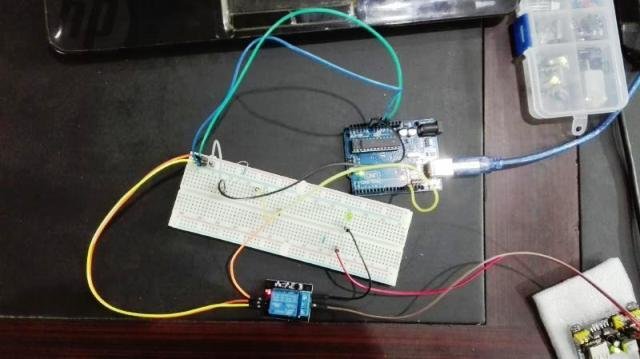
Demonstration
Conclusion
In conclusion, the light sensor and street light control system using Arduino is a practical and efficient solution for automatically adjusting street lights based on the detected light intensity. By utilizing components such as the Arduino UNO R3, light-dependent resistor (LDR), and relay, the system accurately measures and converts the analog light intensity into digital values for controlling the street lights. The Arduino code provided allows for seamless execution of the system, ensuring that the lights are switched on or off based on the specified light threshold. This project offers an effective way to conserve energy and enhance safety on the streets.
You may also like to read:
- APDS9960 Proximity, Gesture, and Ambient Light Sensor Interfacing with Arduino
- BH1750 Ambient Light Sensor Interfacing with Arduino
- DC Motor Control with LabVIEW and Arduino
- Arduino Rosserial Publish Range HC-SR04 Ultrasonic Readings to ROS
- Voltage Sensor Module Interfacing with Arduino
- Interface DS1307 RTC Module with Arduino – Display Date/Time on OLED
how to control the intensity of light?
how to control intensity
what about 100 in code
your code is not compiling …
what are you are getting?
what the device name of the series?
which device?
I need circuit diagram for arduino based solar street light.please help me
i wann this circuit interfacing using 8051 microcontroller
Arduino: 1.6.8 (Windows 7), Board: “Arduino/Genuino Uno”
sketch_mar26b:15: error: stray ‘\342’ in program
light_value = 100 – light_value/10.24;
^
sketch_mar26b:15: error: stray ‘\200’ in program
sketch_mar26b:15: error: stray ‘\223’ in program
I:\ALL btech chandana\third year sem-2\minip\implementation\four\sketch_mar26b\sketch_mar26b.ino: In function ‘void loop()’:
sketch_mar26b:15: error: expected ‘;’ before ‘light_value’
light_value = 100 – light_value/10.24;
^
exit status 1
stray ‘\342’ in program
iam getting above error
exit status 1
stray ‘\226’ in program
there is an error in the code and it says..
“exit status 1
stray ‘\226’ in program”
Hello I am designing a smart street light but I am having problem over-riding the LDR
Sequenc of operation-
-3 Leds are wired to light together.
-The Leds should light only when the ambient light level is > 600.
-If a movement sensor detects movement, the Leds should light at full brightness during the period that movement is detected.
-After no further movement is detected, the Leds should remain at full brightness for 3 seconds then dim (be on half brightness ? ) for 2 seconds then switch fully off.
Please help
sir i am doing this project with both LDR and RTC.i want code for that
Please help me with codes please