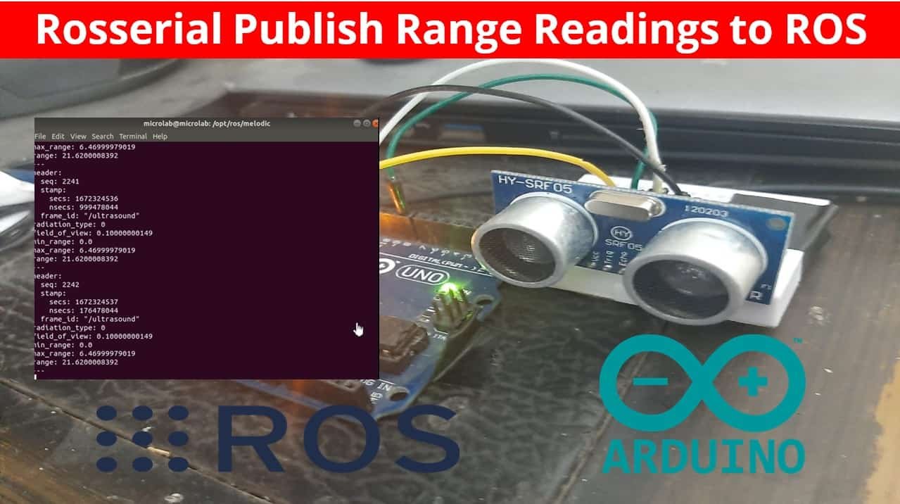
In this tutorial, we will create a ROS Range publisher Node on Arduino that publishes HC-SR04 ultrasonic sensor readings on ROS “/ultrasound” topic using rosserial and how to read range topic readings in ROS. Before that, we will introduce you to HC-SR04 sensor and interface it with Arduino to build the Arduino ROS range publisher node.
Before we move ahead, make sure you have Arduino IDE and ROS installed on your machine. Moreover, the rosserial package should be installed on your machine as well. You can refer to our previous getting started guide before moving further.

Recommended Components
The following components are used in this project or are helpful for building it with the Arduino.
| Component | How it’s used in this project | Buy on Amazon |
|---|---|---|
| Arduino Uno R3 | The board that reads the ultrasonic sensor and publishes range readings to ROS over rosserial. | Check Price |
| Breadboard | Holds the sensor and wiring while you build the circuit. | Check Price |
| Jumper Wires | Connect the Arduino trigger and echo pins to the HC-SR04. | Check Price |
| HC-SR04 ultrasonic sensor | Measures distance via trigger/echo pulses; its range readings are published to the ROS /ultrasound topic. | Check Price |
As an Amazon Associate we earn from qualifying purchases. Prices and availability are accurate as of the date/time indicated and are subject to change.
Interface HC-SR04 Ultrasonic sensor with Arduino
To interface the HC-SR04 ultrasonic sensor with Arduino, we should know the functionality of each pin of the ultrasonic sensor. By knowing the functionality of input and output pins, we will be able to identify which GPIO pins of Arduino should be used to interface with HC-SR04.
HC-SR04 Pin Details
The figure given below shows its pin configuration. It consists of four pins namely: VCC, Ground, Trigger, and Echo pin.
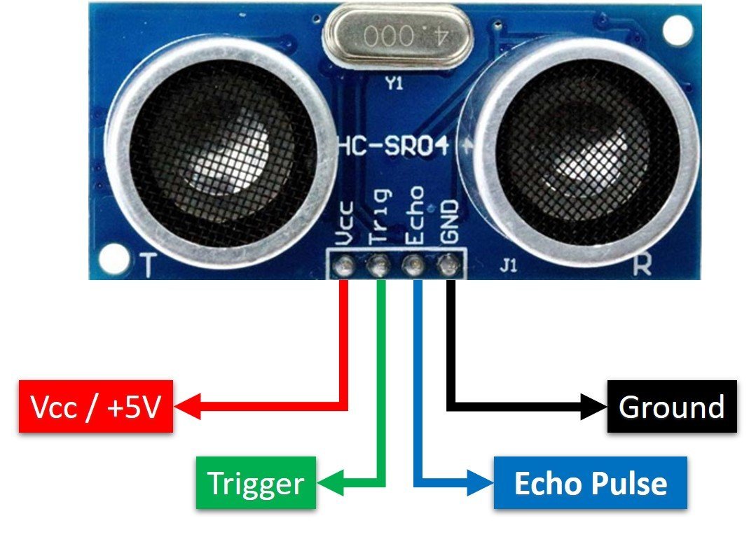
Vcc and Ground are used to power sensor. We should supply 5 volts to the Vcc pin and connect the GND pin with the ground terminal of the power supply. about:blank
Trigger: It is an input pin. Trigger pin is used to initiate the ultrasonic sensor to start distance measurement or distance ranging. When users want to get distance measurements from the sensor, we apply a 10µs pulse to this pin.
Echo: This is a pulse output pin. The echo pin produces a pulse as an output. The width of pulse or on-time of the pulse depends on the distance between the ultrasonic sensor and obstacle which is placed in front of the HC-SR04 sensor. In idle conditions, this pin remains at an active low level.
Connection Diagram Ultrasound Sensor with Arduino
Until now we have seen the working of the ultrasonic sensor and the pin details. Now we know that to interface an HC-SR04 sensor with Arduino, we need four pins out of which two are power supply pins and two are digital input output pins. One GPIO pin of the Arduino will be used as a digital output pin to provide a trigger signal to the ultrasonic sensor. Similarly, one GPIO pin will be used as a digital input pin to capture echo output signal of output sensor.
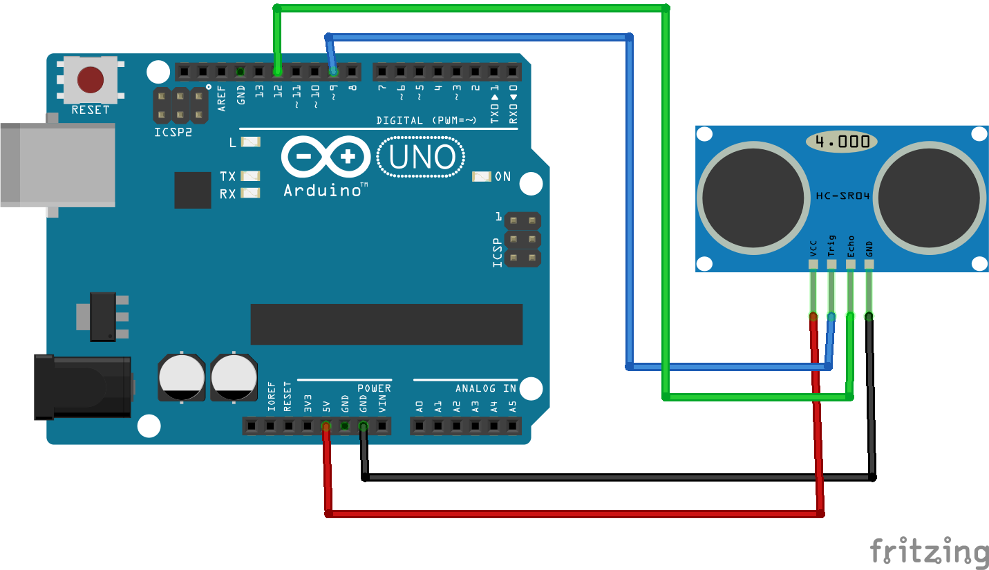
Now make the connection of the Arduino with the HC-SR04 sensor according to this connection diagram. In this schematic diagram, we use pin 9 of Arduino to provide a trigger signal and pin 12 to capture the echo output pulse.
| HC-SR04 | Arduino |
|---|---|
| Vcc | +5V |
| GND | GND |
| Trigger | Pin 9 |
| Echo | Pin 12 |
Install Arduino Rosserial library in Arduino IDE
Open your Arduino IDE in Linux, and go to Sketch > Manage Library > Include Library. This opens the Arduino Library Manager.
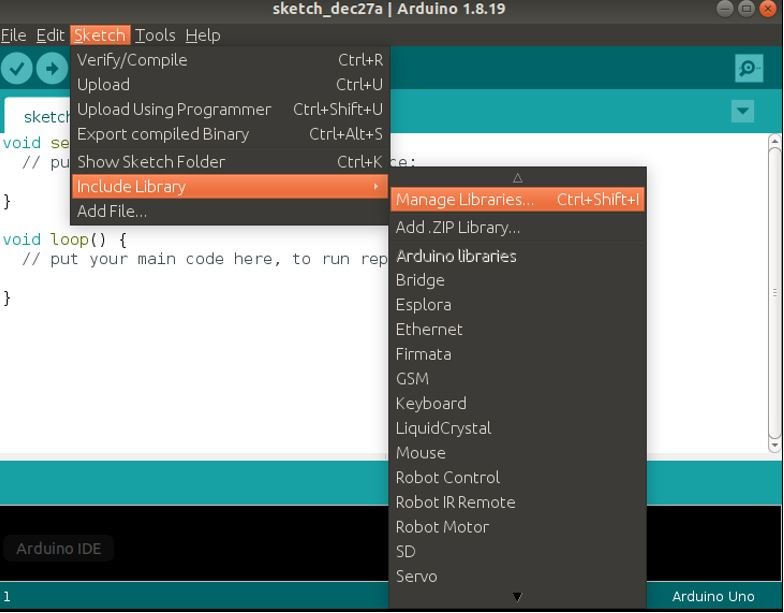
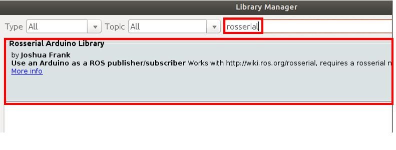
We will install the ros_lib package in Arduino IDE using the library manager. Type ‘rosserial’ in the search bar and press enter.
Install the latest version of the Rosserial Arduino Library by Joshua Frank.
Arduino Rosserial HC-SR04 Range Publisher Node Code
In the following code, Arduino publishes the range of HC-SR04 ultrasonic sensor to the topic /ultrasound.
#include <ros.h>
#include <ros/time.h>
#include <sensor_msgs/Range.h>
#define USE_USBCON

ros::NodeHandle  nh;

sensor_msgs::Range range_msg;
ros::Publisher pub_range( "/ultrasound", &range_msg);

int trigger_pin = 9;
int echo_pin = 12;


long range_time;
char frameid[] = "/ultrasound";


void setup() {
  nh.initNode();
  nh.advertise(pub_range);
  range_msg.radiation_type = sensor_msgs::Range::ULTRASOUND;
  range_msg.header.frame_id =  frameid;
  range_msg.field_of_view = 0.1;
  range_msg.min_range = 0.0;
  range_msg.max_range = 6.47;
}

void loop()
{
  if ( millis() >= range_time ){
      range_msg.range = getRange() / 100;
      range_msg.header.stamp = nh.now();
      pub_range.publish(&range_msg);
      range_time =  millis() + 50;
    }
    nh.spinOnce();
}

long microsecondsToCentimeters(long microseconds)
{
// The speed of sound is 340 m/s or 29 microseconds per centimeter.
// The ping travels out and back, so to find the distance of the
// object we take half of the distance travelled.
return microseconds / 29.1 / 2;
}

float getRange()
{
  long duration;

  //PING is triggered by a HIGH pulse of 2 or more microseconds.
  // Give a short LOW pulse beforehand to ensure a clean HIGH pulse:
  pinMode(trigger_pin, OUTPUT);
  digitalWrite(trigger_pin, LOW);
  delayMicroseconds(2);
  digitalWrite(trigger_pin, HIGH);
  delayMicroseconds(10);
  digitalWrite(trigger_pin, LOW);

  // The same pin is used to read the signal from the PING))): a HIGH
  // pulse whose duration is the time (in microseconds) from the sending
  // of the ping to the reception of its echo off of an object.
  pinMode(echo_pin, INPUT);
  duration = pulseIn(echo_pin, HIGH);

  // convert the time into a distance
  return microsecondsToCentimeters(duration);
}
Working of the Code
The code starts by including the necessary libraries required for this project. ros.h library is vital for the ROS whereas ros/time.h is used for the ROS clock time. The sensor_msgs is the ROS package that contains a collection of messages which are usually used for common sensors. As we are using HC-SR04 sensor therefore we will use the Range.h header file for the message type. The Range message type is used to transmit a single range reading from HC-SR04 that is accurate along an arc at the measured distance.
#include <ros.h>
#include <ros/time.h>
#include <sensor_msgs/Range.h>
Then the instance of the NodeHandle is created called ‘nh.’ This will be used later on to create the publisher and initialize it.
ros::NodeHandle nh;Next, create an instance for range message.
sensor_msgs::Range range_msg;Then, we create an instance of the Publisher pub_range() which takes in two parameters. The first parameter is the name of the topic which is “/ultrasound” and the second parameter is the reference to the instance that we created for the message that will be published.
ros::Publisher pub_range( "/ultrasound", &range_msg);After that, we define the names of Arduino pins using #define preprocessor directives. This defines that pin 9 and pin 12 of Arduino are used to control trigger and echo pins of the HC-SR04 sensor. Hence, through the program, we will use these symbolic names instead of pin numbers.
int trigger_pin = 9;
int echo_pin = 12;
setup()
Inside the setup() function, the ROS node is initialized and the publisher is created using the advertise() method. This publisher will be responsible to publish the ranges on the topic ‘/utrasound.’
Next, we set the parameters of the Range message object. This includes the radiation_type of the sensor, the frame_id which is the point of reference for the data, the field_of_view which is the size of the arc in radians for which the reading is valid, the min_range and the max_range values which are valid.
void setup() {
  nh.initNode();
  nh.advertise(pub_range);
  range_msg.radiation_type = sensor_msgs::Range::ULTRASOUND;
  range_msg.header.frame_id =  frameid;
  range_msg.field_of_view = 0.1;
  range_msg.min_range = 0.0;
  range_msg.max_range = 6.47;
}
loop()
Inside the loop() function, after every 50ms we obtain the range from the HC-SR04 ultrasonic sensor and divide it by 100, then we obtain the current time by using nh.now(). The range reading is then published by the node. The spinOnce() method ensures that the ROS serial communication is handled appropriately.
void loop()
{
  if ( millis() >= range_time ){
      range_msg.range = getRange() / 100;
      range_msg.header.stamp = nh.now();
      pub_range.publish(&range_msg);
      range_time =  millis() + 50;
    }
    nh.spinOnce();
}
getRange()
Inside the getRange() function, we obtain the measured range from the ultrasonic sensor.
float getRange()
{
  long duration;

  // PING is triggered by a HIGH pulse of 2 or more microseconds.
  // Give a short LOW pulse beforehand to ensure a clean HIGH pulse:
  pinMode(trigger_pin, OUTPUT);
  digitalWrite(trigger_pin, LOW);
  delayMicroseconds(2);
  digitalWrite(trigger_pin, HIGH);
  delayMicroseconds(10);
  digitalWrite(trigger_pin, LOW);

  // The same pin is used to read the signal from the PING))): a HIGH
  // pulse whose duration is the time (in microseconds) from the sending
  // of the ping to the reception of its echo off of an object.
  pinMode(echo_pin, INPUT);
  duration = pulseIn(echo_pin, HIGH);

  // convert the time into a distance
  return microsecondsToCentimeters(duration);
}
First of all, we configure the trigger pin as an output pin. As you know that to enable the ranging of data from the HC-SR04 sensor, we provide a 10µs pulse to the trigger pin. Therefore, this segment of code provides a 10µs pulse to trigger pin. It will initiate the distance sample taking process.
  // PING is triggered by a HIGH pulse of 2 or more microseconds.
  // Give a short LOW pulse beforehand to ensure a clean HIGH pulse:
  pinMode(trigger_pin, OUTPUT);
  digitalWrite(trigger_pin, LOW);
  delayMicroseconds(2);
  digitalWrite(trigger_pin, HIGH);
  delayMicroseconds(10);
  digitalWrite(trigger_pin, LOW);
As soon as we apply a 10µs pulse to the ultrasonic sensor, in response, it produces 40KHz sonar waves and raises the Echo output signal to an active high state. The echo output signal remains active high until these sonar waves reflect back to the ultrasonic transmitter. As soon as the receiver circuit received these waves, the echo output signal goes to an active low level. Hence, this line measures the timer for which the output signal remains in an active high state.
  pinMode(echo_pin, INPUT);
  duration = pulseIn(echo_pin, HIGH);
This time is converted into a distance reading which is returned by the function.
return microsecondsToCentimeters(duration);We call the microsecondsToCentimeters() function to convert the time in microseconds to centimeters. It is defined below as follows:
long microsecondsToCentimeters(long microseconds)
{
// The speed of sound is 340 m/s or 29 microseconds per centimeter.
// The ping travels out and back, so to find the distance of the
// object we take half of the distance travelled.
return microseconds / 29.1 / 2;
}
Upload Code to Arduino UNO
Plug your Arduino board into the USB port on your computer. Now head over to Tools > Board and select Arduino UNO and Tools > Port and select the Port through which your Arduino is connected. In our case, it is /dev/ttyACM0
Now click the upload button to upload the code to Arduino board.
In order to successfully upload this sketch to your board, we will have to modify the msg.h file. Head over to Arduino > libraries > Rosserial_Arduino_Library > src > ros > msg.h and open it. Change #include <cstring> to #include <string.h> (line 40) and std::memcpy() to memcpy() (lines 68 and 182)
You can get the following error message while uploading the code.
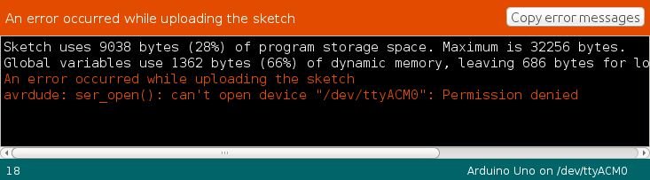
If this happens, open a terminal and type the following command and press enter. This will identify the port and list it in the system.
sudo chmod a+rw /dev/ttyACM0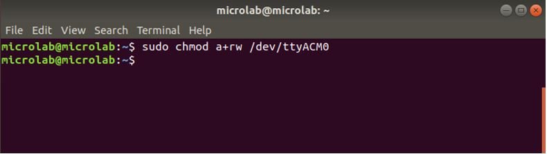
Now upload the code to Arduino again and it will be successfully uploaded.
Run the Code
After the code is successfully uploaded, open a new terminal. Type the following commands and press enter:
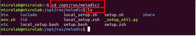
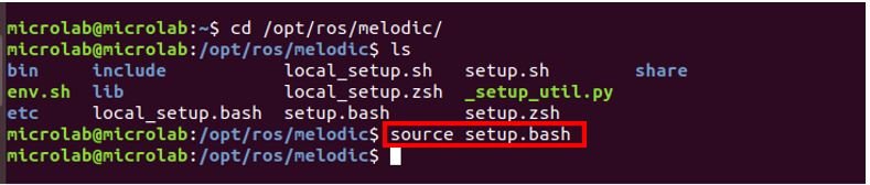
This shows that ROS Melodic is installed on our machine. Now to run any ros commands we have to set up the ROS environment first. We have to source setup.bash script. Hence type the following command and press enter:
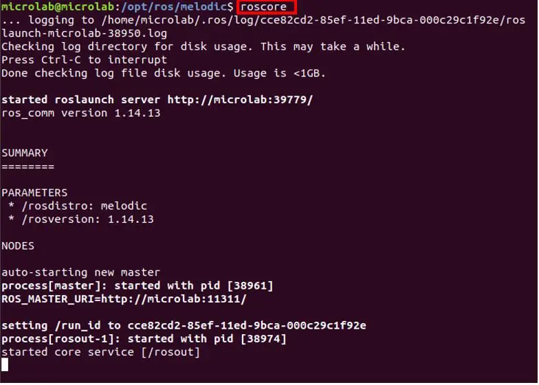
Now to launch the ROS Master, type roscore in the terminal and press enter. It gives the following output as shown below:
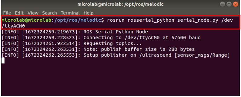
Now open a new terminal to launch the ROS serial server. Type the following command in the terminal and press enter. This will ensure the integration between ROS and Arduino. Make sure to enter the correct port through which your Arduino is connected.
rosrun rosserial_python serial_node.py /dev/ttyACM0This is the output that we get. Note that it connects to the serial port, requests the topics and setups the publisher on /ultrasound.
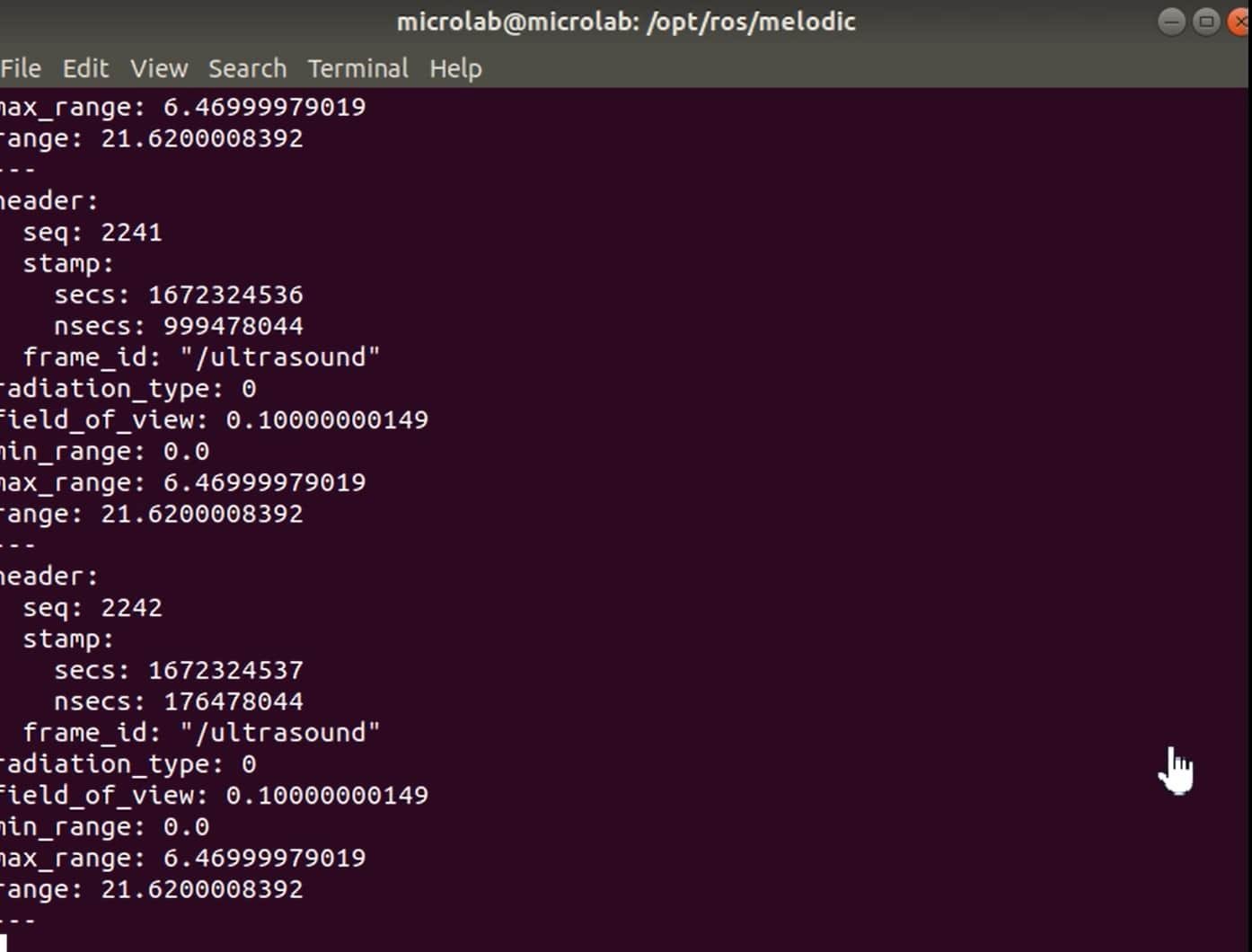
To view the messages open a new terminal and navigate to the ROS melodic folder. Then source the setup.bash and type the following command to view the messages coming from Arduino.
rostopic echo /ultrasoundYou can view the different ranges of /ultrasound that we obtained: