In this tutorial, we will learn to interface the 0-25V DC voltage sensor module with Arduino and program it for voltage measurement. This guide includes an introduction to the voltage sensor module, its pinout, connection with Arduino and then programming our Arduino with the sensor to display the measured voltage readings on an OLED.
Recommended Components
The following components are used in this project or are helpful for building it with the Arduino.
| Component | How it’s used in this project | Buy on Amazon |
|---|---|---|
| Arduino Uno R3 | Reads the sensor’s analog output on A0 and displays the measured voltage. | Check Price |
| Breadboard | Holds the sensor module and OLED for the measurement circuit. | Check Price |
| Jumper Wires | Connect the sensor’s analog pin and the OLED’s I2C pins to the Arduino. | Check Price |
| 0.96″ SSD1306 OLED Display | Displays the measured DC voltage reading from the sensor module. | Check Price |
As an Amazon Associate we earn from qualifying purchases. Prices and availability are accurate as of the date/time indicated and are subject to change.
0-25V DC Voltage Sensor Module
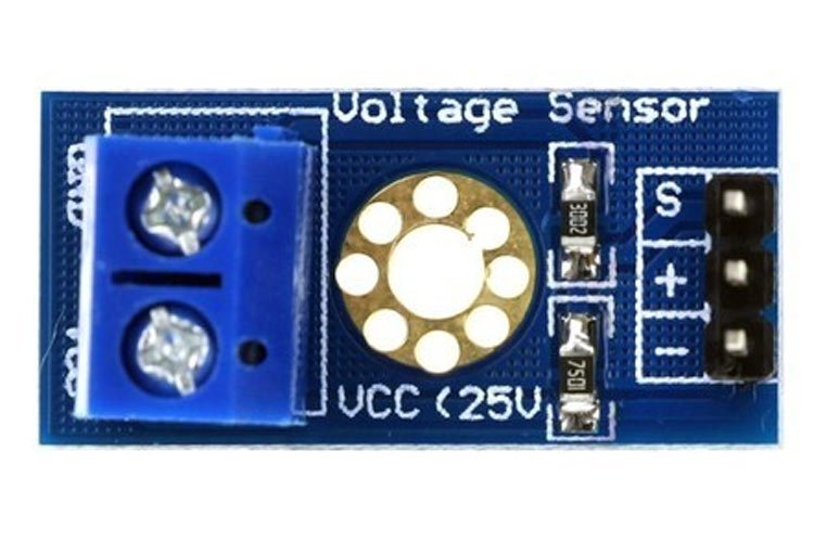
The voltage sensor module is a small size 0-25 DC voltage sensing device. The design of the module is based on a resistive voltage divider circuit. It is a voltage sensor module that reduces the input voltage signal by the factor of 5 and generates a corresponding analog output voltage with respect to step down voltage factor. This voltage measurement circuit is small and portable and can be used to detect under and over-voltage faults in electrical circuits.
The post is a brief description of the voltage sensor module pinout, pin configuration, interfacing with Arduino with an example code and applications.
Voltage Sensor Module Pinout
The voltage sensor module is embedded with two header blocks. One with the screws is connected to the power source whose voltage to be measured while the other connector is used to interface microcontrollers such as Arduino, Pic microcontroller, Raspberry Pi, Beaglebone, etc. The pinout of the voltage sensor module is shown below:
Pin Configuration
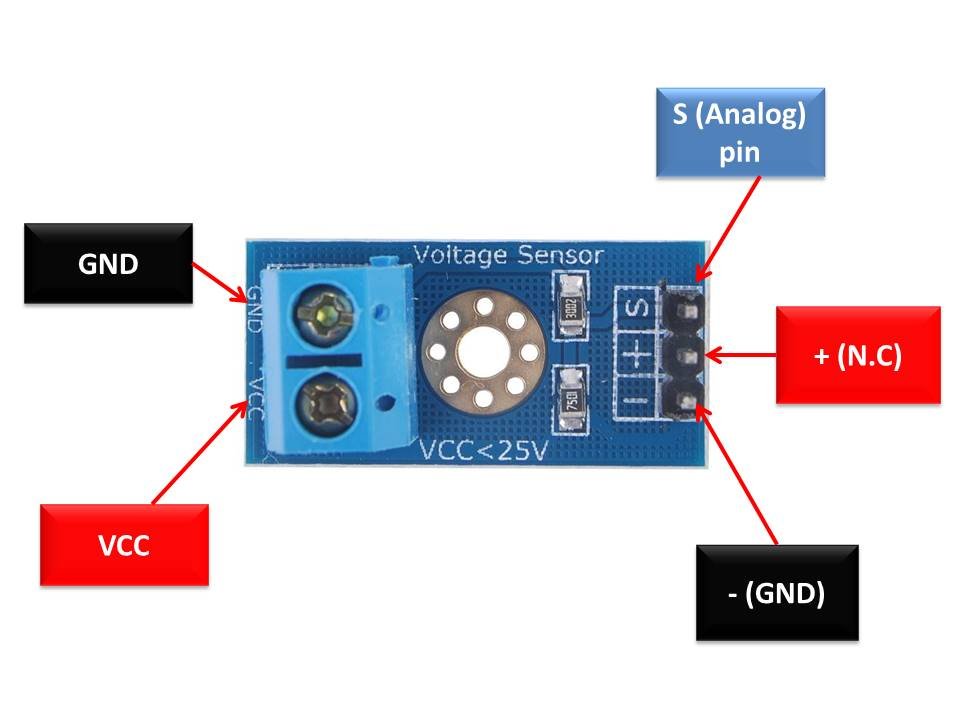
The pin configuration details of voltage sensor module are given below.
This module is available in 4cm x 3cm x 2cm dimensions.
| Pin Name | Function |
|---|---|
| VCC | Positive power supply pin. The positive terminal of the power supply to be measured is connected to this pin. |
| GND | Reference potential pin. It is connected to the negative terminal of the power supply. |
| S | Analog output pin voltage of sensor. Connect it to the analog input pin of Arduino or any other microcontroller which you want to use. |
| + | Not connected |
| – | Ground connection pin. It must be joined to the ground pin of the Arduino or microcontroller and also to the power supply ground pin. |
Features & Specifications
- Input Voltage: 0 Volts – 25 Volts
- Voltage measurement Range: 0.02445 Volts – 25 Volts
- Analog signal resolution: 0.00489 Volts
- Voltage Sensor module dimensions: 4cm x 3cm x 2cm
- It is a small, portable and reliable device.
- The module is a simple circuitry and easy to interface with Arduino microcontrollers.
Schematic Diagram
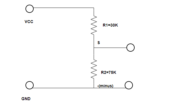
The schematic diagram of the voltage Sensor module which is a resistive voltage divider is shown below:
Voltage Sensor Module Working Principle
The voltage sensor module works on the voltage divider principle. A voltage divider is a circuit made of two resistors connected in series. An input voltage is connected to the circuit. The applied voltage is then passed on between the two resistance and division takes place in direct accordance with the resistances. The output analog voltage is taken from the second resistor and measured. The general equation of the output voltage is
Vout= Vin*R2/R1+R2
The equation shows that the output voltage is directly proportional to the input voltage and the ratio of the R2 resistor to the sum of R1 and R2 resistors.
Important Calculations
Here, we will calculate the range of the concerned voltage sensor module and the resolution of the output signal.
Example
We know that the maximum analog voltage that the Arduino board can take is 5 Volts i.e V1=5 Volts. So, the maximum voltage that the voltage sensor module can take is calculated using Ohm’s Law.
The resistances used in the voltage sensor module are R1=30K, R2= 7.5K
I=V/R
Therefore,
I = 5/7500 = 0.000666 = 666uA
As R1 and R2 are in series, the current is the same for both the resistors. That means IR2 is also 666µA. We can find the voltage across R1 as
VR1= 666uA x 30000 = 20 Volts
The maximum voltage that the module can measure is the sum of the voltage drops.
VR1+VR2=5V+20V= 25V.
Analog Signal Resolution
The Arduino boards have an analog to digital converter with a resolution of 10-bits. So, the resolution of the analog signal that is given out is
Resolution= 5V/2^10 = 5/1024= 0.00489 Volts
Minimum Voltage
Using the resolution, we can calculate the minimum voltage that is to be provided to the voltage sensor module.
Vmin=0.00489 Volts x 5 Volts=0.02445 Volts
Voltage Sensor Module Interfacing with Arduino and OLED
The section shows the interfacing of the Arduino UNO with the Voltage Sensor module and the OLED. You will require the following components:
Required Components
- Arduino UNO
- 0-25V DC Voltage Sensor Module
- 0-25V Power Supply
- SSD1306 OLED
- Connecting Wires
- Breadboard
The wiring diagram is provided below:
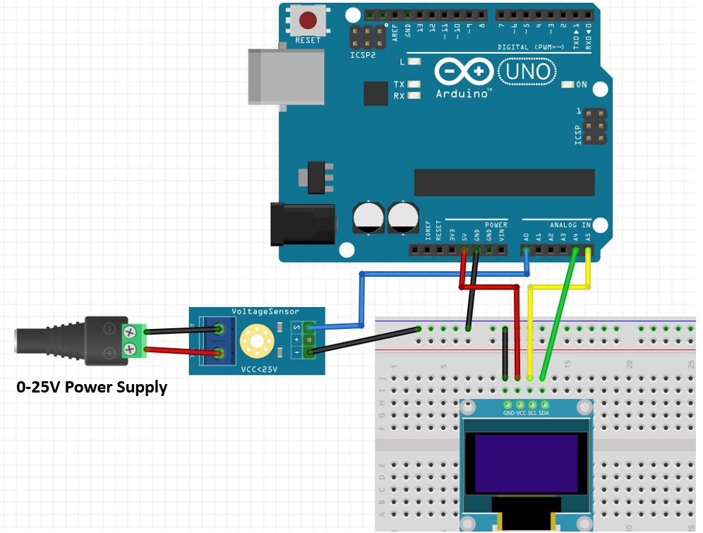
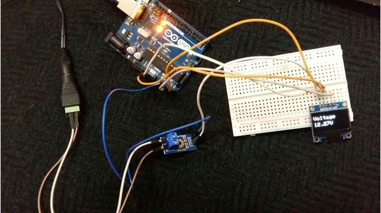
For demonstration purposes we are using 12V 1A power supply.
First, connect the power source whose voltage you want to measure with the input pins of the voltage sensor module. This is done by connecting the ground pin of the voltage sensor to the negative terminal of the battery and the positive power supply pin i.e. VCC to the positive terminal of the battery. Screw the wires tightly. Connect the analog pin S to any of the input analog pins of the Arduino UNO. Similarly, connect the -(minus) pin to the ground pin of the Arduino.
The wiring should be done in accordance with the tables given:
| Arduino UNO | Voltage Sensor Module |
|---|---|
| A0 | S |
| GND | -(minus) |
| Power Source | Voltage Sensor Module |
|---|---|
| + | VCC |
| – | GND |
| Arduino UNO | OLED |
| 5V | VCC |
| GND | GND |
| A5 | SCL |
| A4 | SDA |
Voltage Sensor Module with Arduino Display on OLED Code
Make sure to install Adafruit SSD1306 OLED library in Arduino IDE by going to Tools > Library Manager.
The Arduino code for Voltage Sensor module is provided below:
#include <Adafruit_GFX.h>
#include <Adafruit_SSD1306.h>

int offset = 20;// set the correction offset value

Adafruit_SSD1306 display = Adafruit_SSD1306(128, 64, &Wire, -1);

void setup() {
  Serial.begin(115200);

  if (!display.begin(SSD1306_SWITCHCAPVCC, 0x3C)) {
    Serial.println(F("SSD1306 allocation failed"));
    for (;;);
  }
  delay(2000);
  display.clearDisplay();
  display.setTextColor(WHITE);
}

void loop() {
  int volt = analogRead(A0);// read the input
  double voltage = map(volt, 0, 1023, 0, 2500) + offset; // map 0-1023 to 0-2500 and add correction offset

  voltage /= 100; // divide by 100 to get the decimal values
  Serial.print("Voltage: ");
  Serial.print(voltage); //print the voltge
  Serial.println(" V");

  //display on OLED
  display.setCursor(0, 10);
  display.setTextSize(2);
  display.clearDisplay();
  display.print("Voltage ");
  display.setTextSize(2);
  display.setCursor(0, 35);
  display.print(voltage);
  display.print(" ");
  display.setTextSize(2);
  display.setCursor(60, 35);
  display.print("V");
  display.display();

  delay(500);

}
How Does the Code Work?
The voltage sensor module does not require any pre-written Arduino libraries for its interfacing with the Arduino microcontrollers. It works ideally without using the built-in libraries in the Arduino IDE software. We need only to use the AnalogRead() function of Arduino IDE to measure analog output of the voltage sensor.
Include OLED Libraries
We will start off by including the necessary libraries for this project which includes the OLED libraries are the ones which we previously installed and are required for the proper functionality of the OLED display.
#include <Adafruit_GFX.h>
#include <Adafruit_SSD1306.h>
Voltage Offset
A voltage offset of 20 is used as a correction value to the input analog signal in case the module is not working fine. Otherwise set the offset to zero.
int offset = 20;Adafruit_SSD1306 Object
Then, we create an object of Adafruit_SSD1306 and specify the width, height, I2C instance (&Wire), and -1 as parameters inside it.’ -1′ specifies that the OLED display which we are using does not have a RESET pin. If you are using the RESET pin then specify the GPIO through which you are connecting it with your development board.
Adafruit_SSD1306 display = Adafruit_SSD1306(128, 64, &Wire, -1);setup()
The next statement is the setup block. In the code, the setup block initializes the serial monitor with a baud rate of 115200 bits per second. We need it to display the values of the analog voltage signal.
Moreover, we also initialize the OLED display by using display.begin(). Make sure you specify the correct address of your OLED display. In our case, it is 0X3C.
Then, we clear the buffer by using clearDisplay() on the Adafruit_SSD1306 object. Next, we control the color of the text by using the setTextColor() function and pass WHITE as an argument.
void setup() {
  Serial.begin(115200);

  if (!display.begin(SSD1306_SWITCHCAPVCC, 0x3C)) {
    Serial.println(F("SSD1306 allocation failed"));
    for (;;);
  }
  delay(2000);
  display.clearDisplay();
  display.setTextColor(WHITE);
}
loop()
Inside the loop, an integer variable “volt ” is initialized. The analog value is read through the pre-defined analogRead() function and stored in it. The next instruction line is the map function which maps one set of values to another set of values. It has five parameters. The first one is the variable “volt” whose values are to be mapped. The values would be between 0 and 1023 because the Arduino has a 10-bit inbuilt analog to digital converter and mapped them in range 0 to 2500.
We are mapping the initial range in the latter range because if we map them between 0 and 25, we get one volt increment and won’t obtain values in between. Hence, after mapping and adding the offset, the result is stored in the “voltage” which is further divided by 100 to get the decimal point. Finally, these are displayed on the Serial monitor and there is a delay of 500 milliseconds before the next value is read. The lesser the delay, the faster the values will be read. To test the module, upload the code on the Arduino UNO and see the measurements on the monitor and the OLED.
void loop() {
  int volt = analogRead(A0);// read the input
  double voltage = map(volt, 0, 1023, 0, 2500) + offset; // map 0-1023 to 0-2500 and add correction offset

  voltage /= 100; // divide by 100 to get the decimal values
  Serial.print("Voltage: ");
  Serial.print(voltage); //print the voltge
  Serial.println(" V");

  //display on OLED
  display.setCursor(0, 10);
  display.setTextSize(2);
  display.clearDisplay();
  display.print("Voltage ");
  display.setTextSize(2);
  display.setCursor(0, 35);
  display.print(voltage);
  display.print(" ");
  display.setTextSize(2);
  display.setCursor(60, 35);
  display.print("V");
  display.display();

  delay(500);

}
Then, we display the voltage reading along with unit on the OLED. This is achieved by first clearing the display, setting the text size, setting the cursor position and then printing the text using display.println().
  display.setCursor(0, 10);
  display.setTextSize(2);
  display.clearDisplay();
  display.print("Voltage ");
  display.setTextSize(2);
  display.setCursor(0, 35);
  display.print(voltage);
  display.print(" ");
  display.setTextSize(2);
  display.setCursor(60, 35);
  display.print("V");
  display.display();
Demonstration
In Arduino IDE, click Tools > Board and select Arduino.

Now, click Tools > Port and choose the port which you are using. Now, upload the code by clicking on the upload button.
After you have uploaded the following code on your Arduino development board, press the RESET button as follows:

The OLED will start displaying the voltage reading.
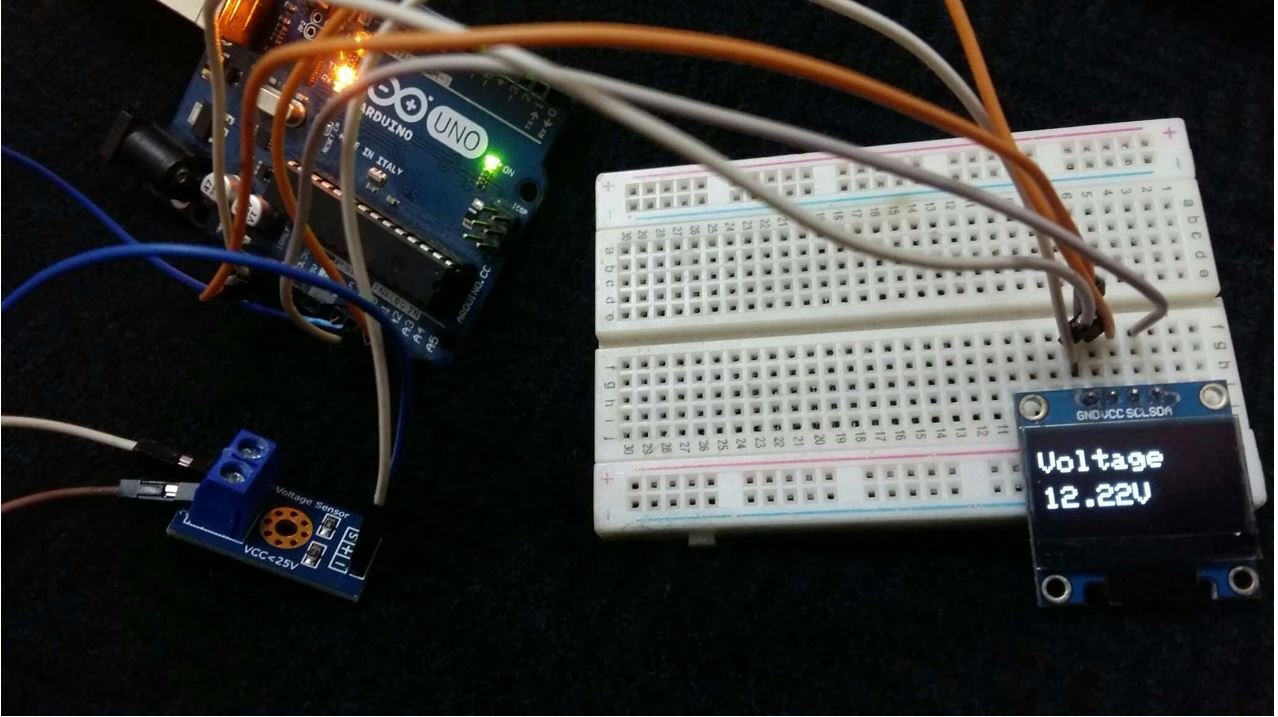
Moreover, the Arduino serial monitor also continuously prints the voltage values.

Voltage Sensor Applications
- Voltage measurement
- Fault sensing
- Safety switching
- Power Control
Related Voltage measurement projects:
- ADC TM4C123G Tiva C Launchpad – Measure Analog Voltage Signal
- How to use ADC of ESP32 – Measuring voltage example
- AC Voltage Measurement using Arduino – Difference Amplifier Technique
- Three phase voltage measurement using pic microcontroller
- Analog voltage reading using Arduino UNO R3
- AC Voltage measurement using PIC16F877A microcontroller
Other modules:
where do you make the visual schematic with custom components like the voltage sensor? similar to tinkercad?