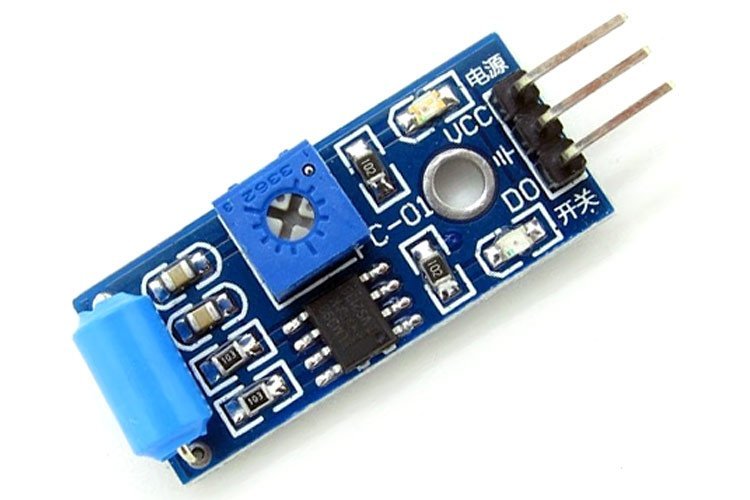
SW-420 is a cost-effective vibration sensor module consists of SW-420 and Comparator LM393. The module is embedded with an SW-420 Vibration Sensor, a 10K potentiometer to alter the sensitivity, and an LM393 comparator that produces a smooth digital output. The LM393 comparator uses a preset to sense the vibrations in the surroundings and maintains a state. It gives out logic high if vibrations are detected otherwise it will remain in its default logic low state. The module is a handy, easy interface with a device that finds its applications in DIY projects along with commercial applications.
In this tutorial, we will learn SW-420 configuration, specifications, and how to use a vibration sensor with the Arduino UNO.
Recommended Components
The following components are used in this project or are helpful for building it with the Arduino.
| Component | How it’s used in this project | Buy on Amazon |
|---|---|---|
| Arduino Uno R3 | The main microcontroller board that runs the sketch and reads the sensors/modules in this project. | Check Price |
| Breadboard | Lets you wire the components to the Arduino without soldering for quick prototyping. | Check Price |
| Jumper Wires | Connect the Arduino pins to the module and other parts on the breadboard. | Check Price |
| 5mm LED | Blinks to alert when the SW-420 vibration sensor detects vibration. | Check Price |
| Resistor Kit (220Ω/4.7kΩ) | Provides the current-limiting resistor for the indicator LED. | Check Price |
As an Amazon Associate we earn from qualifying purchases. Prices and availability are accurate as of the date/time indicated and are subject to change.
SW-420 Vibration Sensor Components
The SW-420 vibration sensor module is integrated with the SW-420 vibration sensor, LM393 voltage comparator, a potentiometer, current limiting resistors to act as voltage dividers, therefore, control the current and capacitors as biasing elements and for noise filtering.
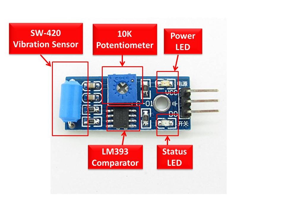
LM393 Voltage Comparator IC
It is a high-precise integrated circuit that compares the reference voltage and the input vibration signal. Pin 2 of the LM393 IC is connected to the adjustable potentiometer while its pin 3 is connected to the vibration sensor. The IC compares both the voltages and passes them to the digital output pin in the form of binary states.
Potentiometer
A 10K potentiometer is placed on the module to adjust the sensitivity of the sensor. The sensitivity can either be increased or decreased depending on the requirement. It is done by setting a preset or a threshold value which is given to the LM393 as a reference to compare.
SW-420 Vibration Switch
The SW-420 vibration switch senses the magnitude of the vibration in its environment. It responds to the exposed vibration either through the opening or closing of the electrical contact. The trigger switch can be an electromechanical or relay or semiconductor component.
Inbuilt LEDs
The module has two LEDs. One is to light up when the module is energized and the other is to indicate the digital output.
SW-420 Vibration Sensor Pinout
The SW-420 vibration sensor module is available in 3.2cm x 1.4cm dimensions. The pinout of the Vibration Sensor module is as shown:
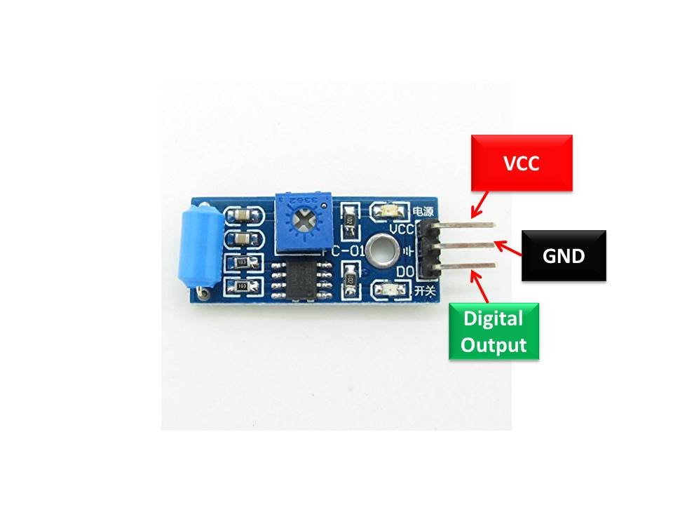
SW-420 Pin Configuration
It has three headers for interfacing with any microcontroller. The pin configuration in tabular are detailed below:
| Pin Name | Function |
|---|---|
| VCC | Positive power supply pin. It gives power to the sensor. |
| GND | Ground connection pin |
| D0 | Digital output pin. It passes the digital output of the builtin comparator circuit. |
Features & Specifications
- Operating Voltage: 3.3 Volts – 5.0 Volts DC
- Current driving Capability: 15 mA
- Vibration Sensor module dimensions: 3.2cm x 1.4cm
- The vibration sensor is a close type switch by default.
- An internal 10K potentiometer is given to calibrate the sensitivity of the sensor.
- A low-power voltage LM393 comparator chip to binarize the analog signal and has a driving ability of 15 mA is provided in the sensor.
- SW-420 also has two status LEDs for power and output indication.
- The module has a fixed bolt for easy installation.
- It is microcontroller-friendly and can be interfaced with any of them.
SW-420 Working Principle
The SW-420 is a switch that operates by the opening and closing of the electrical contact. By default, the vibration sensor is in a closed state. When no vibrations are sensed, it remains closed or in a conduction state. As soon as vibration is detected by the sensor, the contacts open and the resistance rises. Due to this, a pulse is produced and triggers the circuit. It is passed on to the LM393 voltage comparator IC that digitizes the signal and further makes it available on the digital output pin of the module.
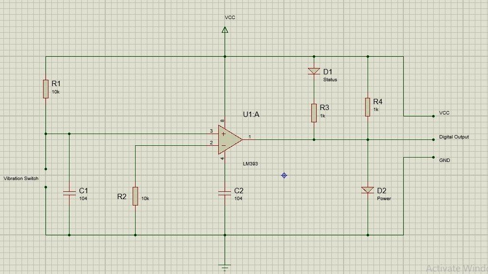
Circuit Diagram
The concerned SW-420 vibration module has three connections i.e VCC, GND, and D0. The power pins of the microcontroller are connected to these pins while the digital output pin which is internally connected to the output pin of the comparator is joined to one of the output pins of the microcontroller.
The functional diagram of the SW-420 Vibration Sensor module for grasping the knowledge of the internal connections of the module is provided below:
SW-420 Vibration Sensor Interfacing with Arduino
This part describes the interfacing of the Arduino UNO and SW-420 Vibration Sensor module. In this section, we are designing a circuit in such a way that whenever vibrations are detected by the vibration sensor module, the LED starts blinking to alert us about them.
Connection Diagram
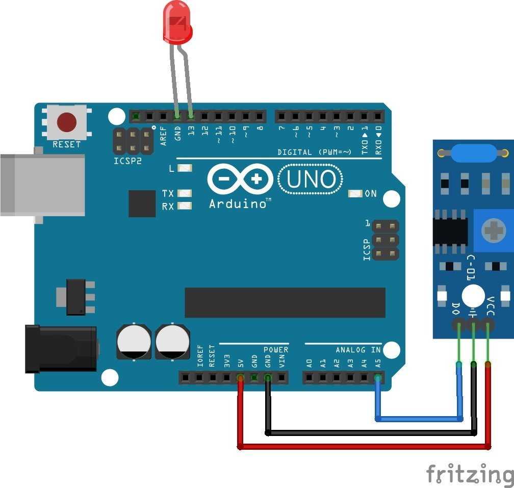
- First, supply the power to the vibration sensor. For that purpose, connect the positive power supply pin to 3.3 Volts or 5 Volts pins and the ground pin of the vibration sensor module to the GND pin of the Arduino UNO.
- Connect the digital pin D0 to any of the digital pins of the Arduino.
| Arduino UNO | Vibration Sensor |
|---|---|
| 5V(Red) | VCC |
| GND(Black) | GND |
| A5(Green) | D0 |
| Arduino UNO | Light Emitting Diode |
|---|---|
| D13 | Anode pin |
| GND | Cathode pin |
Arduino Code
The Arduino code for the SW-420 Vibration Sensor module is provided below:
/*//==============================================================================//
 * SW-420 Vibration Sensor Module Interfacing with Arduino
 * Author: Microcontrollerslab.com
 */ //=============================================================================//
#include <Arduino.h>
#include <stdio.h>

//define on/off logic symbols with name ON and OFF
#define ON HIGH
#define OFF LOW

#define Sensor_Out_Pin A5
#define LED_Pin  13

int present_condition = 0;
int previous_condition = 0;

void setup() {
pinMode(Sensor_Out_Pin, INPUT);
pinMode(LED_Pin, OUTPUT);
}


void LED_Pin_blink(void);

void loop() {
previous_condition = present_condition;
present_condition = digitalRead(Sensor_Out_Pin); // Reading digital data from the A5 Pin of the Arduino.

if (previous_condition != present_condition) {
LED_Pin_blink();

} else {
digitalWrite(LED_Pin, OFF);
}
}

void LED_Pin_blink(void) {
digitalWrite(LED_Pin, ON);
delay(250);
digitalWrite(LED_Pin, OFF);
delay(250);
digitalWrite(LED_Pin, ON);
delay(250);
digitalWrite(LED_Pin, OFF);
delay(250);
}
How does the code work?
Include libraries: SW-420 can be interfaced easily with Arduino UNO through Arduino IDE or Eclipse IDE software. The code provided above is actually written in Eclipse IDE software with Arduino extension. So, we have to include the “Arduino.h” header file. If the respective code will be written in Arduino IDE, it does not require any Arduino.h header file.
Code Explanation
Defining macros and pins: At the start of the sketch, two macros are defined for two constants. ON means 1 and OFF means 0. We need to define pins for the Arduino to take in the data from the vibration sensor and after processing display it through the LED. So, A5 and D13 of the Arduino are integrated respectively.
Variables Declaration
To compare the values, two integer type variables i.e previous condition and present condition to store the current and previous data are declared and initialized.
Setup Function
The direction of the pins or pin mode is configured in this block. The data is to be received from the sensor so its respective pin mode is an INPUT whereas the LED has to show the result taken from the Arduino UNO, it is set as OUTPUT.
LED_Pin_blink function
A mini-function for the LED has been written to be called in the void loop. According to this function, the LED will blink twice with a delay of 250 milliseconds.
loop Function
In this segment, the binary value obtained from the module is received, stored, and compared. Initially, the variables present and previous condition hold zero. The data would be read in the present condition through the analogRead() function and is then stored and compared with the previous condition.
Now, if any vibrations are sensed, the present condition will be one and thus compared with the previous condition. They are not equal so the function led_blink() is called and led starts blinking until the end of the vibrations. Hence, the process repeats.
Testing the circuit
Upload the code. Make some vibrations either by tapping the table on which the module is placed or move the module and evaluate the LED. It keeps blinking unless it senses nothing.
SW-420 Vibration Sensor Applications
- Earthquake Detection
- Alarm systems
- Object Detection Systems
- Intelligent Automobiles
Related Modules:
Pic16f877a Water level control code Please Sent
hi,
what is the highest threshold for sensitivity?
For example, can I mount this on a fence and have it triggered only when something big has hit the fence with a large force… example a car striking the fence, but not a bicycle, or a human?