CP2102 UART module is the upgraded version of RS-232 Communicator introduced by Silicon Labs. It is a single CP2102 chip USB to UART Bridge with 12Mbps USB full speed. CP2102 possesses a high-performance, inbuilt transceiver for serial data along with suspend/resume signals for the energy control of the chip and external circuitry also. The module supports handshaking and also processes the command requests made by the USB host to control the activities of the asynchronous serial UART port.
Moreover, it contains a PROM of 1024 bytes and a 48 MHz internal oscillator. The device is embedded with two voltage regulators and matching pull-up resistors.CP2102 is compatible with Windows/Linux/Mac OS-X/OS-9 and existing COM ports. However, it requires drivers to start the serial communication. The tutorial is a guide to the pinout, specifications, features, working, and applications.
Recommended Components
The following parts are used in this article, along with a generic electronics kit that is handy for building and testing the circuit.
| Component | How it’s used | Buy on Amazon |
|---|---|---|
| CP2102 USB-to-UART module | The CP2102 USB-to-serial module this article covers, used to program boards and for UART comms. | Check Price |
| Electronic component assortment kit (1390 pcs) | A handy assortment of resistors, capacitors, LEDs, diodes and transistors for building circuits. | Check Price |
| Digital multimeter (AstroAI) | Measures voltage, current, resistance and checks continuity while you build and debug. | Check Price |
| Breadboard | Solderless base for prototyping the circuit. | Check Price |
| Jumper Wires | Make the connections on the breadboard. | Check Price |
As an Amazon Associate we earn from qualifying purchases. Prices and availability are accurate as of the date/time indicated and are subject to change.
CP2102 Components
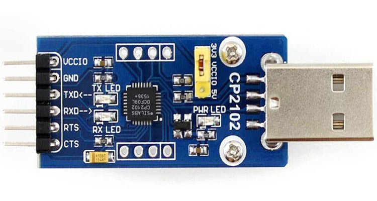
CP2102 USB to UART Bridge module consists of CP2102 chip, Modem Interface Signal port, Control port, UART data transmission plus control ports, power port, and built-in TX & RX LEDs.
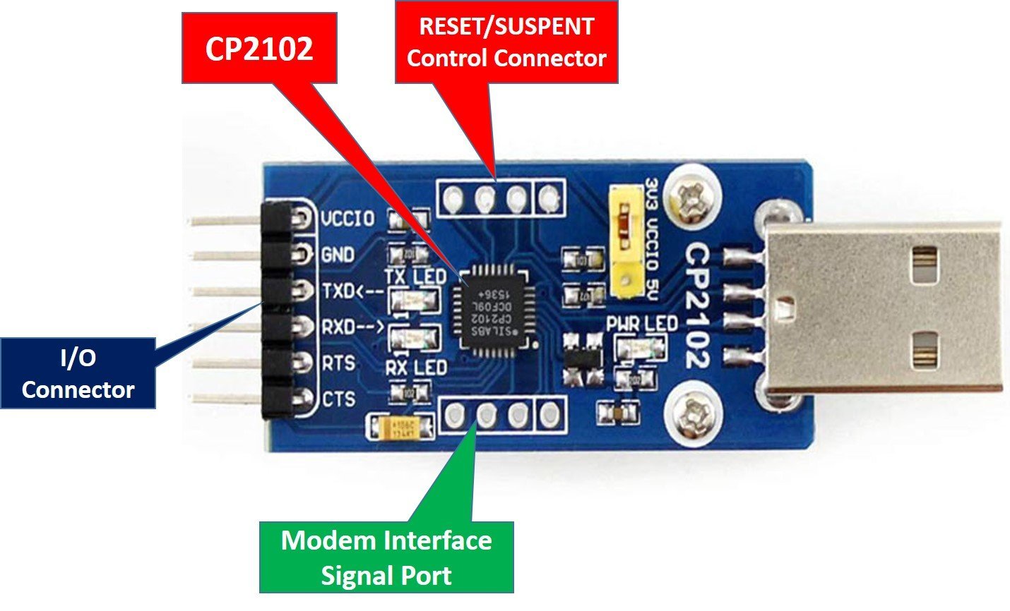
Modem Interface Signal port
Control port: The port is responsible for power management and resetting of the module.
UART data transmission port: The module uses this asynchronous serial communication port for information transfer.
UART Hardware control ports: RTS and CTS are hardware control signals for durable data connection between transmitter and receiver.
Power port: VCCIO and GND pins supply input power to the module.
TX/RX LED: These LEDs indicate the functioning of the respective pins.
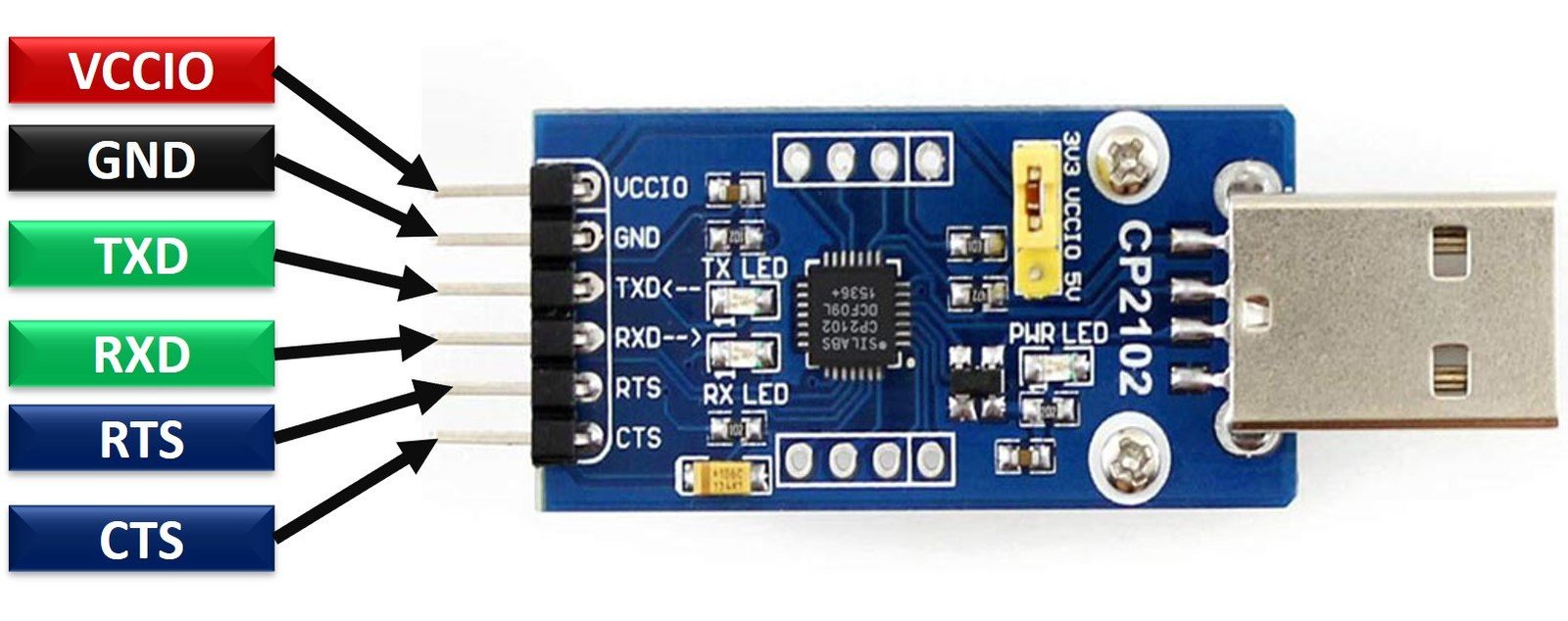
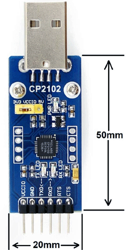
CP2102 Pinout
The pinout of the compact CP2I02 UART module is as shown:
Pin Configuration
The pin configuration in tabular are detailed as below:
| Pin Name | Function |
|---|---|
| VCCIO | Positive Power Supply pin |
| GND | Ground pin |
| RST | Reset pin |
| TXD | UART Serial Transmission pin |
| RXD | UART Serial Reception pin |
| CTS | Active low Clear-to-Send input pin. It supports the Xon/Xoff handshake mechanism. |
| RTS | Active low Ready-to-Send output pin It supports the Xon/Xoff handshake mechanism. |
| DSR | Active low Data Set Ready input pin. It shows that it is ready to accept the data.. |
| DTR | Active low Data Terminal Ready output pin. It shows that the terminal is ready for data transfer. |
| DCD | Active low Data Carrier Detect input pin. It indicates when a good carrier is received from the modem. |
| SUSPEND | Active high USB suspend state pin |
| SUSPEND | Active low USB suspend state pin |
| RI | Active low Ring Indicator input pin. When it changes its state, a hardware interrupt is produced. |
CP2102 Specifications
- Operating Voltage: 3.0 – 3.6 Volts
- Operating Temperature: –400C to +850C
- Output Sink Current: 100mA (max)
- USB pull up Supply Current: 230uA
- USB Connector: Type-A
- Internal Clock Frequency: 48 MHz
- UART Baud Rates: 300 bps -1 Mbps
- Maximum Baud Rate: 921600 bps
- Programmable ROM: 1024 Bytes
- Reception buffer: 576 Bytes
- Transmission buffer: 640 Bytes
- Package Type: 28-pin QFN package (RoHS-compliant)
- Dimensions: 50mm x 20mm
CP2102 Features
Some of the additional features of the USB to UART module are described below:
- ICP2102 UART module is integrated with a high-speed transceiver.
- The CP2102 has a 12Mbps full-speed USB Specification 2.0 compliant.
- The module is embedded with two voltage regulator circuits i.e. 3.3V and 3.45V and a reset circuit.
- For the power control, the module is integrated with Suspend pins.
- It supports the XOn/XOff handshake mechanism.
- CP2102 is compatible with existing drivers and COM ports.
- The module requires no external pull-up resistors.
CP2102 Block Diagram
The block diagram to understand the internal circuitry of the TTL CP2102 UART module is as shown:
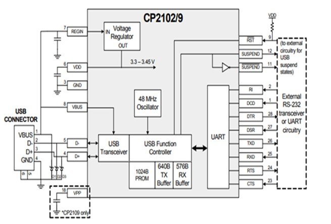
How data transmission happens?
The small chipset is plugged into the PC through the USB port. RX and TX signals of the microcontroller unit and the module are connected. The modules serve as a serial port to the host PC. Host PC sends the information, and the module converts them to UART signals which are communicated over the UART protocol to the microcontroller.
Interfacing Arduino Pro Mini
Arduino pro mini and other Arduino modules which does not come with onboard USB programmer can be programmed with this USB to serial converter chip.
Install CP2102 UART Module Drivers
Before using this module, you need to install drivers. When you plug this USB module with a computer USB port, the required drivers will be installed automatically. But if drivers are not installed automatically, you will need to install them manually. The initial step is to install drivers to get things working. Follow these steps to install the drivers. Go to Silabswebpage:
- Software and Tools > CP210x Windows Drivers > Download and Install
- Open Device Manager and check the COM port.
If it is detected, it is ready to be used. Open Arduino IDE > Tools > Board > Select Arduino Mini Pro. Then go to Tools > Serial Port > Select COM port.
Connecting Diagram
Connect the pins of CP2102 UART Module with Arduino Mini Pro according to the table provided down below:
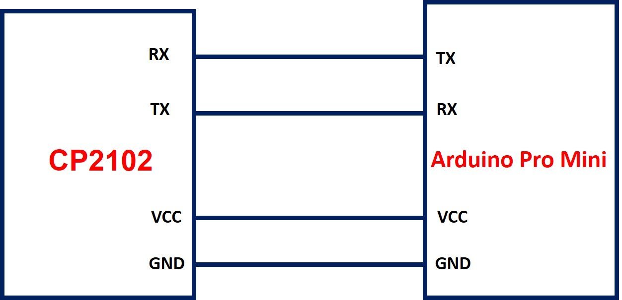
| Arduino Pro Mini | CP2102 Module |
|---|---|
| VCC | VCCIO |
| GND | GND |
| RXI | TXD |
| TX0 | RXD |
| DTR | DTR |
Arduino Code
/*
  Blink

  Turns an LED on for one second, then off for one second, repeatedly.

  Most Arduinos have an on-board LED you can control. On the UNO, MEGA and ZERO
  it is attached to digital pin 13, on MKR1000 on pin 6. LED_BUILTIN is set to
  the correct LED pin independent of which board is used.
  If you want to know what pin the on-board LED is connected to on your Arduino
  model, check the Technical Specs of your board at:
  https://www.arduino.cc/en/Main/Products

  modified 8 May 2014
  by Scott Fitzgerald
  modified 2 Sep 2016
  by Arturo Guadalupi
  modified 8 Sep 2016
  by Colby Newman

  This example code is in the public domain.

  http://www.arduino.cc/en/Tutorial/Blink
*/

// the setup function runs once when you press reset or power the board
void setup() {
  // initialize digital pin LED_BUILTIN as an output.
  pinMode(LED_BUILTIN, OUTPUT);
}

// the loop function runs over and over again forever
void loop() {
  digitalWrite(LED_BUILTIN, HIGH);   // turn the LED on (HIGH is the voltage level)
  delay(1000);                       // wait for a second
  digitalWrite(LED_BUILTIN, LOW);    // turn the LED off by making the voltage LOW
  delay(1000);                       // wait for a second
}
Code Explanation
The above code is very simple to understand the working of the UART module. The code above will blink the inbuilt LED 13 of the Arduino Mini Pro three times to display the data communication between the PC and Arduino Mini Pro through the CP2102 USB-to-UART module.
Make sure to select the right board and COM port. Upload the code. Press the reset button while the code is being compiled. Release the button as it says Done uploading. Observe that the Arduino Mini LED will start blinking three times in a row. This confirms the Serial communication of code from the host computer to the microcontroller through USB to UART module.
Applications
- Data Communication
- Debug Purposes
- Microcontroller programming
- Prototypes
2D Diagram
Related Articles:
Do you have link where to purchase the CP2102 UART module?
I need the Cp2101 to connect to an arduino to use the arduino as a HOST. I have a device, Victron BMV-12 continuing broadcasting serial at 19200 bd. I want the arduino to read this. Hooked it up as follows: VCC -> 5V; GND -> Gnd; RX -> Pin D3; TX -> Pin D2; Used the following script to read the serial input from the BMV-712; It does not print the data from the BMV-12, but I know the BMV-12 is broadcasting because I see the data on the serial monitor ComX port in windows.
// HiLetgo CP2102 USB 2.0 to TTL Module Serial Converter
// HiLetgo TxD (yellow) => Ard D2
// HiLetgo RxD (Orange) => Ard D3
#include
SoftwareSerial mySerial(2, 3); //RS232 RX, TX
void setup()
{
// Open serial communications and wait for port to open:
Serial.begin(19200);
while (!Serial) {
; // wait for serial port to connect. Needed for Native USB only
}
Serial.println(“Goodnight moon!”);
// set the data rate for the SoftwareSerial port
mySerial.begin(19200);
}
void loop()
{
char CharInput;
String TestSentence = “”;
Serial.println(“Checking Availability”);
while (mySerial.available()) {
CharInput = mySerial.read();
TestSentence += CharInput;
}
Serial.println(TestSentence);
delay (1000);
}