In this tutorial, we will discuss the workings of a single phase voltage source inverter. We will design and simulate it with the help of Simulink. At first, we will provide a simple introduction to the single phase voltage source inverter. After this, we will design its Simulink model, and lastly, we will simulate it to get the results.
Introduction to Single Phase Voltage Source Inverter
A single phase voltage source inverter inverts the DC voltage into square-wave ac or sine-wave ac voltages. Currently, there are two types of voltage inverters on the market: the first is a full-bridge voltage source inverter, which consists of four switches, IGBTs, or MOSFETs, and the second is a single-phase voltage source inverter, which consists of two switches, IGBTs, or MOSFETs. These voltage source inverter applications include single phase UPS and switching power supplies. These have been mostly used in high-power static power topologies.
Simulink Model of Single Phase Voltage Source Inverter
In this article, we will explain how we can make a single phase voltage source inverter as well as how we choose the components with the help of the MATLAB Simulink model. First, we will explain how we can make a new model in MATLAB. To make a new model, just open MATLAB and click on the Simulink library. After clicking on Simulink Library, a new page will open with the name “Simulink Library Browser”. We can see this in the figure below.

This Simulink library browser has different options on its menu bar. Just click on New Model, and the New Model page of Simulink will open as shown below.

Simulink Library Browser
On this new Simulink model, we can make our new circuit and then run or simulate it as we want. For choosing the power electronic components, just write power electronics word on the search menu bar of the Simulink library browser. Then a new page will open with all the power electronics component blocks, as shown below.
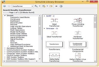
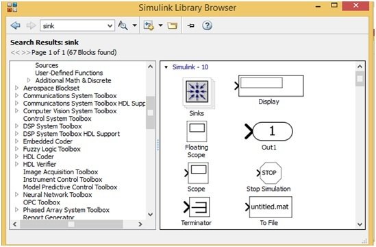
For inserting these blocks on a new model, just drag these blocks onto the new model window, or right-click on the block and then click on Add block to the new model, and this block will automatically copy to the new model window. In this way, we can easily add these blocks to the New Model window. Similarly, for searching oscilloscope and display blocks, just write the word sink on the search menu bar of the “Simulink Library Browser”, and all the relevant blocks will appear on a new page as shown in the figure below.
Simulink Model
Similarly, we search and drag all the other component blocks, such as the pulse generator, logic gate, capacitor, resistor, etc. Then we join the circuit according to our requirements. Now our single phase voltage source inverter is complete with the help of the MATLAB Simulink library. The Simulink model circuit can be seen in the figure below.
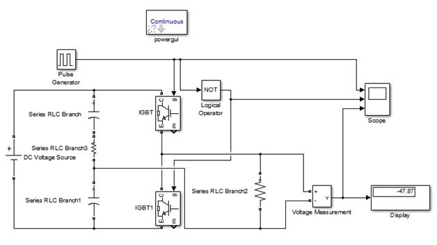
This single-phase voltage source inverter Simulink model uses two IGBTs, two 50 μF capacitors, a 100 V DC voltage supply, and one NOT Gate logic operator. We also had to attach a one-ohm resistor between two capacitors because MATLAB Simulink did not allow us to simulate this circuit without this resistor, but in hardware there is no need to join this resistor. Lastly, we use a 10 Ω resistor as an output load. Now, we run or simulate this circuit at a 50% duty cycle. The duty cycle is set by double-clicking on the pulse generator and then according to the figure below.

Simulation
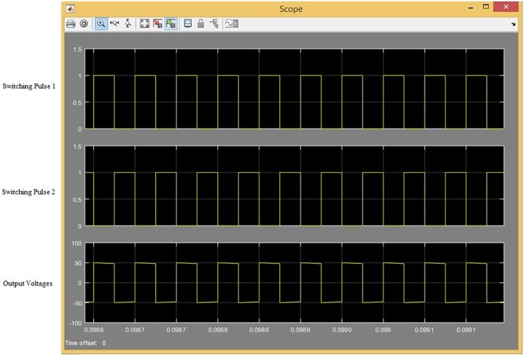
Because both IGBT switches should not be ON at the same time, one gate pulse directly connects with one IGBT switch, and the other gate pulse is connecting with the other IGBT switch after NOT Gate. In other words, this circuit works through complementary switching. When we simulate this circuit at 50% duty cycle, then the output voltage would be half of the supply voltage, which means it would be 50 volts, as shown in the figure below.
Video Demonstration
Conclusion
In conclusion this tutorial provides an in-depth overview for designing and simulating a single phase voltage source inverter using Simulink. It covers step-by-step procedure along with explanation to help us better understand the concept. You can utilize this concept to design and simulate more complex voltage source inverters. Hopefully, this tutorial was helpful in expanding your knowledge in regards to designing and simulating using Simulink MATLAB.
You may also like to read:
- ESP32 Send Sensor Readings to ThingSpeak using Arduino IDE (BME280)
- Raspberry Pi Pico W Send Emails with SMTP Client and MicroPython
- Create a Wi-Fi Manager for ESP32 using AsyncWebServer library
- BME680 Web Server with ESP32 ( Arduino IDE)
- Arduino Comparator Tutorial with Example
- STM32 I2C Communication Guide – HAL Code Examples Slave & Master – DMA Interrupt
- forward converter design and simulation with Simulink
This concludes today’s article. If you face any issues or difficulties, let us know in the comment section below