Generating three-phase sine waves is integral to various industrial applications, especially in the realm of power electronics. This process involves the use of a three-phase sine wave generator circuit, which is capable of producing three individual sine waves that can be easily observed at the output points. By adjusting the values of the components in the circuit diagram, the frequency of the generated sine waves can be modified to meet specific requirements. In this article, we will delve into the working principle of a three-phase sine wave generator circuit, explore its various applications, and discuss how it contributes to the generation of sinusoidal pulse width modulation in three-phase sine wave inverters. Let’s dive in and unlock the intricacies of this essential circuit.
Three Phase Sine Wave Generator Introduction
A three-phase sine wave generator circuit diagram is used to generate three sine waves, with each individual sine wave easily observable at the output points. By using an oscilloscope, the sine waves can be visualized at the three outputs. This type of generator is commonly employed to produce reference signals for three-phase sine wave inverters, enabling the generation of sinusoidal pulse width modulation. The frequency of the generated sine waves can be adjusted by modifying the values of the components utilized in the circuit diagram.
If you are interested in learning more about pure sine wave inverters, I have posted several articles on the topic, which you may find helpful:

Circuit Diagram
The three-phase sine wave generator circuit works based on the principle of an oscillator circuit using resistors, capacitors, and transistors. Let’s dive into the working principle of the circuit:
- Oscillator Circuit: The core of the circuit is the oscillator, which is formed by the combination of resistors and capacitors. The resistors (R1, R2, R3) and capacitors (C1, C2, C3) create a feedback network that produces the oscillations required to generate the sine waves.
- Transistors: Three NPN transistors (Q1, Q2, Q3) are employed to help facilitate the generation process. These transistors act as switches that control the flow of current through the circuit.
- Phase Shift: By properly selecting the values of the resistors and capacitors in the oscillator network, a phase shift is introduced between the three oscillating signals. This phase shift is crucial to achieve the desired three-phase sine wave output.
- Synchronization: The three oscillating signals are synchronized in a way that ensures they maintain a constant phase relationship with each other. This synchronization is necessary for the accurate generation of the three-phase sine waves.
- Output Taps: The circuit provides three output taps where the generated sine waves can be observed. These output points can be connected to an oscilloscope or any other visualization device to visualize the sine waves.
- Adjusting Frequency: The frequency of the generated sine waves can be adjusted by modifying the values of the resistors and capacitors in the oscillator network. By changing these values, the timing and period of the oscillations can be altered, allowing for the desired frequency adjustment.
- Powering the Circuit: The entire circuit is powered by a 9V battery (BAT1) to provide the necessary voltage for operation.
By following the circuit diagram and adjusting the resistor and capacitor values, the three-phase sine wave generator circuit generates three individual sine waves that can be observed at the output taps. The synchronized and adjustable nature of this circuit makes it suitable for various applications, such as generating reference signals for three-phase sine wave inverters, power electronics testing, industrial automation, renewable energy systems, and more.
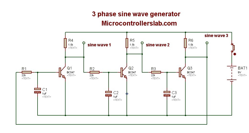
The circuit diagram above illustrates a three-phase sine wave generator, constructed using simple electronic components such as transistors and resistors. Three output taps are provided to monitor the output sine waves produced by this generator. This circuit diagram finds application in various industrial devices. The frequency of the three-phase sine wave generator can be altered by adjusting the values of the resistors and capacitors. A single-pole single-throw switch is employed to toggle the circuit on or off, while a 9V battery powers the entire circuit.
List of Components
Below is a list of components used in this circuit:
| Category | Reference | Value |
|---|---|---|
| Resistors | R1 | 22k |
| Resistors | R2 | 22k |
| Resistors | R3 | 22k |
| Resistors | R4 | 1.5k |
| Resistors | R5 | 1.5k |
| Resistors | R6 | 1.5k |
| Capacitors | C1 | 1uF |
| Capacitors | C2 | 1uF |
| Capacitors | C3 | 1uF |
| Transistors | Q1 | BC547 |
| Transistors | Q2 | BC547 |
| Transistors | Q3 | BC547 |
| Miscellaneous | BAT1 | 9V |
Feel free to adjust the resistor and capacitor values according to your specific requirements, as the generator’s working principle is relatively straightforward. The combination of a resistor and a capacitor forms an oscillator that generates the three sine waves. In this circuit, three BC547 NPN transistors are employed to facilitate the generation process.
Applications
The three-phase sine wave generator circuit has numerous applications in various industries. Here are some common applications:
- Reference Signal Generator: The generator is commonly used to produce reference signals for three-phase sine wave inverters. These reference signals are essential for generating accurate and efficient sinusoidal pulse width modulation (PWM) signals.
- Power Electronics Testing: The circuit is frequently employed in power electronics laboratories and research facilities to test and validate the performance of power electronic devices, such as inverters, motor drives, and AC power supplies.
- Industrial Automation: The generator is used in industrial automation systems that require precise three-phase sine wave signals for motor control, energy conversion, and power quality analysis. It ensures the reliable and efficient operation of motor drives, servo systems, and other industrial equipment.
- Renewable Energy Systems: The circuit finds application in renewable energy systems, particularly in grid-connected photovoltaic (PV) systems and wind turbines. It produces synchronized output signals to control the power conversion process and ensure proper grid integration.
- Power Conditioning Equipment: The generator is utilized in power conditioning equipment, such as uninterruptible power supplies (UPS), voltage stabilizers, and active power filters. It provides stable and clean three-phase sine wave signals to improve the quality and reliability of the power supply.
- Educational Purposes: The circuit serves as an excellent educational tool for teaching and understanding the principles of three-phase power systems, signal generation, and power electronics. It is commonly used in electrical engineering courses at universities and technical institutions.
- Research and Development: The generator is valuable for research and development purposes in the field of power electronics, renewable energy, and electric vehicle systems. It allows researchers to experiment with different circuit configurations and study the behavior of various power electronic devices.
- Audio and Music Production: The circuit can be utilized in audio and music production to generate precise three-phase sine wave signals for testing and calibrating audio equipment, such as amplifiers, mixers, and audio processors.
- Frequency Conversion Systems: The generator finds application in frequency conversion systems, such as variable frequency drives (VFDs) for motor speed control and frequency converters used in aerospace and defense applications.
- Signal Processing and Communications: The generated three-phase sine wave signals can be utilized in some signal processing applications, such as Fourier analysis and harmonic analysis. Additionally, they can serve as carrier signals in wireless communications and data transmission systems.
These applications highlight the versatility and importance of the three-phase sine wave generator circuit in various fields, enabling efficient power conversion and control.
Conclusion
In conclusion, the three-phase sine wave generator circuit diagram presented in this article offers a practical and efficient solution for generating three sine waves simultaneously. This generator plays a crucial role in providing reference signals for three-phase sine wave inverters, enabling the generation of sinusoidal pulse width modulation. By adjusting the values of the components used in the circuit, the frequency of the generated sine waves can be easily modified according to specific requirements. With its simple construction using readily available electronic components, this circuit diagram finds applications in various industrial devices. It is important to note that the resistor-capacitor oscillator principle lies at the heart of this generator, with three BC547 NPN transistors aiding the generation process. By following the provided circuit diagram and adjusting the resistor and capacitor values, users can create customized three-phase sine waves for their applications with ease.
Related content:
Feel free to explore these articles for more information on various electronic projects and topics.
In this three-phase generator I want to ask you how I can get a much more amplifiering signal.
I can use a TCP 122 for amplifiering or some other ( much more) but I’m not sure how to make the connections.
Please, would you like to show me how can I do this amplifiering.
I would be grateful if you designed it entirely by adding this plan already.
Thank you
P.I
I built this circuit and it certainly wasn’t giving me a sine wave. More of a saw tooth with dead time
you need to play with values of capacitors
MINE WORKED – WHICH FOR THREE TRANSISTORS – QUITE GOOD
It worked – How is the frequency calculated?