A transistor is an electronic component that is also used as a digital switch. It works similarly to a mechanical switch, but it is controlled by a digital high logic signal instead of traditional push buttons. Traditional switches are manually controlled by applying mechanical force.
Transistor Introduction
In the world of electronics, a digital switch plays a significant role in controlling the flow of current, enabling us to create complex circuits and perform various functions. One of the fundamental building blocks of these switches is the PN junction, which is formed by connecting P-type and N-type semiconductor materials.
Semiconductors are materials that have electrical conductivity between conductors (such as metals) and insulators (such as non-metals). The P-type semiconductor contains an excess of positively charged carriers, known as “holes,” while the N-type semiconductor contains an excess of negatively charged carriers, known as “electrons.”
When we bring the P-type and N-type semiconductors together, their oppositely charged carriers begin to diffuse across the junction. This diffusion process creates a region near the junction with an equal number of positive and negative charges, known as the depletion region.
The PN junction acts as a barrier to the flow of current in its natural state. However, by applying a specific biasing voltage across the transistor’s pins, we can modify the characteristics of the junction. This biasing voltage can either forward bias the junction or reverse bias it.
In a forward bias configuration, we apply a positive voltage to the P-type semiconductor and a negative voltage to the N-type semiconductor. This reduces the barrier potential across the PN junction, allowing current to flow freely. The switch is considered “ON” in this state, and current can pass through the circuit connected to the switch.
Conversely, in a reverse bias configuration, we apply a negative voltage to the P-type semiconductor and a positive voltage to the N-type semiconductor. This increases the barrier potential, making it difficult for current to flow across the junction. The switch is considered “OFF” in this state, and no significant current passes through the circuit.
By controlling the biasing voltage applied to the transistor’s pins, we can manipulate the behavior of the PN junction, effectively turning the digital switch “ON” or “OFF.” This capability allows us to create the complex logic gates and circuits that form the foundation of modern digital
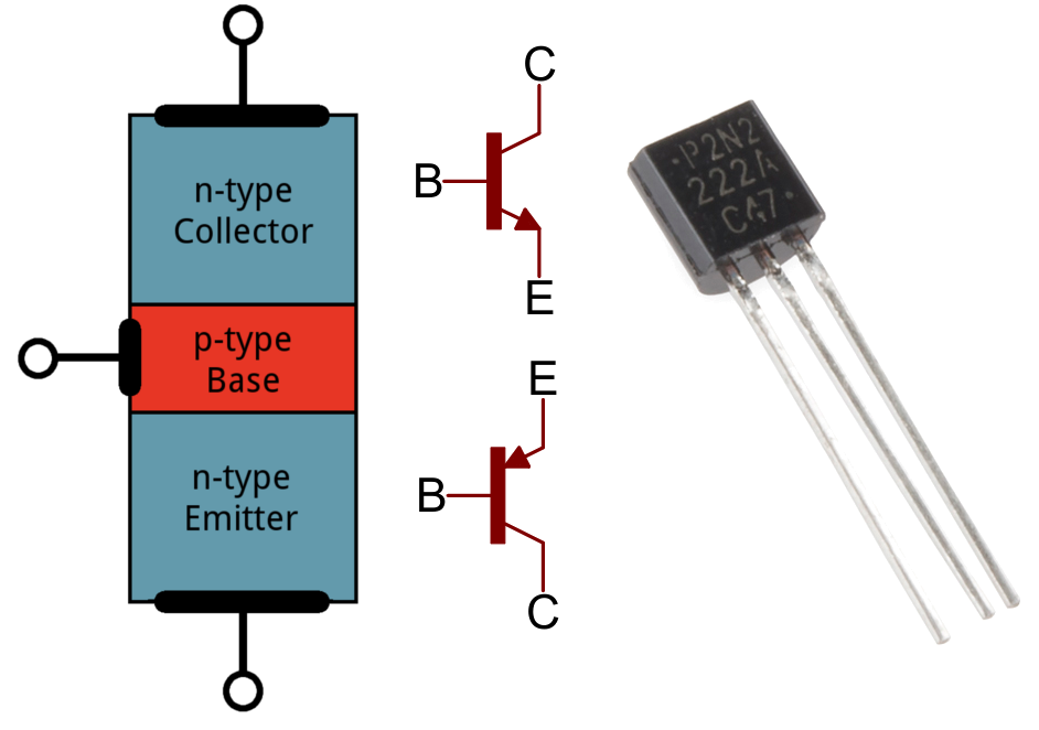
Transistors have two types such as NPN and PNP. It is a three-terminal device. These terminals are:
- Base ( When using as a switch, we apply control logic this terminal)
- Collector
- Emitter
When we apply a biasing voltage to the base terminal, the PN junction breaks down. After that current can flow between collector and emitter terminals. Otherwise, forward current can not flow through the device.

you can check these practical transistors: 2N2222, MPSA42, 2N3906
Using Transistors as Switches
Now we will learn:
- How to use a transistor as a switch in electronic circuits
- how to use it as a switch in microcontroller projects.
Where to use?
In any application, we need to interface a transistor with a microcontroller. But the question that may come to your mind is, “Why do we need to interface a transistor with a microcontroller?” This is because microcontroller pins cannot provide an output current of more than 3mA and a voltage of more than 5V. If we want to connect a load that requires a higher operating current demand of more than 3mA, it will burn the microcontroller. Many output devices will require a transistor switching circuit to operate a high current requirement load, such as relays, solenoids, and motors.
How to use it?
This diagram depicts the three operating regions of the transistor: the saturation region, the active region, and the cut-off region. In the saturation region, it remains fully ON. In the cut-off region, it remains fully off. For switching purposes, we only need this device to operate either in the fully-on or fully-off region. Therefore, we can ignore the Q-Point and switch it between the saturation and cut-off areas.

How do Transistors Work as a Switch?
As we see earlier, we can use two regions only. Now, we will see how a transistor works in these regions.
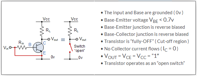
The cut-off region is also known as fully OFF mode. In this mode, it acts as an open switch. To operate the device in cut-off mode, we should connect reverse biasing voltage to both junctions. Therefore, in this operating condition, the current cannot flow between the collector and emitter terminals due to an open circuit between these terminals.
In the saturation region, the transistor remains in full-on mode. The maximum current can flow through the collector to the emitter according to the rating capacity of the transistor. We provide a forward-biased voltage between the base and emitter terminals. It works like a short circuit between the collector and the emitter. The biasing voltage is usually greater than 0.7 volts.

Example of Digital Logic Switches
This PN junction-based device has many applications, such as high current load interfacing, relay interfacing, and motor interfacing through microcontrollers. However, in all these applications, the basic purpose is switching.
This diagram provides an example of how to control high-power loads such as motors, lamps, and heaters.
- In this circuit, we want to control a 12-volt load from a digital logic AND gate. However, the output of the AND gate is only 5 volts.
- By utilizing a transistor as a switch, we can drive 12-volt or even higher voltage loads with a 5-volt digital logic signal.
- We can also employ these devices for faster switching and pulse-width modulation control, unlike traditional mechanical switches.

Motor Controlling Example
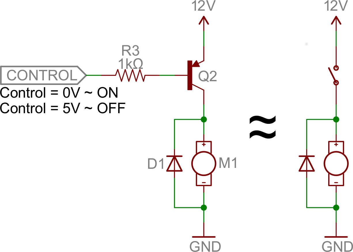
In this example, we use DC motor control through a switch. A semiconductor device acts as a switch. In this diagram, we can provide a control signal with any microcontroller such as Arduino or STM32F4 development boards.
A resistor with a base terminal is a current-limiting resistor because the GPIO pins of any microcontroller can provide a base driving current of less than 20mA. Furthermore, D1 is a freewheeling diode that controls back electromotive force (EMF) from the motor. It bypasses the back EMF effect. We can use any transistor according to the power rating of the motor.
In conclusion, if a control signal at the base input is 0 volts, it will provide an ON signal because we use a PNP switch in this example circuit. Similarly, it will remain off if its control signal is logic HIGH.
Transistor as a Switch with Arduino Example
This diagram shows the interfacing of an Arduino with an NPN transistor and a motor. It is designed for demonstration purposes only. In this circuit, power is supplied to a load through the Arduino. It is important to note that this example can only operate a 5-volt DC motor. If you require the capability to drive a larger power motor, it is advisable to use a special power transistor and a separate power supply.

Transistor as a switch Proteus simulation Example
This example is an exact replication of the prior circuit. But NPN transistor is used instead. Therefore, controlling signals will operate the opposite.

Transistor as a switch Examples
In this section, we will see various examples of using a transistor as a switch.
Two Transistors as a Switch Example
In this circuit, there are two transistors. In the first transistor, the base is grounded and no current can flow into it. As a result, the transistor is “off” and no current can flow through the bulb. In another case, there is current flowing into the base so the transistor is “on” and the current can flow through it resulting in the light bulb being on.

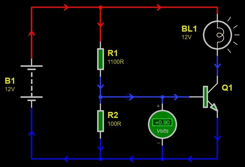
In this example, the two resistors are set so that the base of the transistor is at a sufficiently high voltage for current to flow into it and as a consequence, the transistor is on. As a result, the current flows through the light bulb which is therefore emitting light.
Controlling Transistor Base Current with Potentiometer
In this case, the current flowing into the base can be varied. If the current is large, the transistor is on and the light bulb is lit. If the pointer on the potentiometer is moved downwards, the current into the base drops until the transistor is off and no current flows through the light bulb.
It consists of an NPN transistor, a current-limiting resistor, and a load. Here is how the circuit works:
- Transistor: The NPN transistor, such as 2N2222 or similar, is a three-terminal device with emitter (E), base (B), and collector (C) pins. The transistor acts as a switch in this circuit.
- Resistor: The current-limiting resistor is connected between the base of the transistor and the control signal source, which is usually a microcontroller or any other digital logic device. It helps to limit the amount of current flowing into the base terminal of the transistor.
- Load: The load represents the device or component that we want to control or switch on/off using the transistor. It can be a light bulb, motor, relay, or any other high-current consuming device.
Here’s how the circuit operates:
- Transistor Biasing: When a positive voltage or logic high signal is applied to the base terminal using the control signal source, it forward biases the base-emitter junction of the transistor. This biasing voltage should be greater than the transistor’s threshold voltage, typically around 0.7 volts for silicon-based transistors.
- Transistor “ON” State: With the base-emitter junction forward biased, it allows a current to flow from the collector to the emitter, and the transistor is in an “ON” state. This means that the transistor acts like a closed switch, and current can flow through the collector-emitter path.
- Load Operation: With the transistor in the “ON” state, the load connected to the collector terminal receives power and operates according to its characteristics. For example, if the load is a light bulb, it will glow or if it’s a motor, it will start rotating.
- Transistor “OFF” State: When the control signal at the base terminal becomes low or logic zero, it reverse biases the base-emitter junction of the transistor. As a result, the transistor enters the “OFF” state, acting like an open switch, and no current flows through the collector-emitter path.
- Load Deactivation: With the transistor “OFF,” the flow of current to the load is stopped, and it ceases operation. For example, the light bulb will turn off, or the motor will stop rotating.
By controlling the input control signal at the base terminal of the transistor, we can effectively switch the load connected to the collector terminal on or off. This allows us to interface low-power control circuits, like microcontrollers, with high-power-consuming devices safely and efficiently.
Controlling a Relay with a Transistor as a Switch
In this example, the principle is the same as the last circuit example except that instead of a light bulb being switched on and off a relay coil is activated, and this in turn switches on the light bulbs in the secondary circuit.
Controlling Transistor Switch Operation with a Capacitor
This example circuit uses a capacitor to control the current flow to the base terminal of a transistor. Initially, the capacitor is charged up via the resistor above it. Eventually, the upper plate of the capacitor reaches such a potential that a current begins to flow into the base of the transistor, switching the transistor on and causing the bulb to shine.

You should also note that the lamp remains off until enough charge is stored inside the capacitor to provide the turn-on current to the base terminal of the transistor.
In this example circuit, the capacitor charges up until its lower plate is at such a low potential that no current can flow into the base of the transistor. The result is that the transistor is initially on, but then after a period of time is switched off. In this and last circuits, there is a timing effect. After a certain period of time, which can be determined by the choice of resistor and capacitor, the transistor is either switched on or off.

This example circuit of a transistor as a switch is similar to the circuit of the last example, except that by varying the value of the variable resistor, it is possible to vary the time it takes before the transistor is switched on.

Video lecture

Practically we used mostly relays for high current demanding loads. In that case, the transistor used to operate the relay and load is connected with a relay.
Transistor as switch Applications
- Control high-voltage lamps, motors, and heaters
- Pulse width modulation high-frequency switching
- Acts as an amplifier
Related Articles:
- Zero Crossing Detection Circuits Examples
- Introduction to 3D Printing, Working and Applications
- Light Emitting Diode
- Introduction to UART Communication
- Difference between CRT Monitor and LCD
- Digital To Analog Converter Introduction and DAC Types
- Thermocouple introduction, working and types
- Different Types of Fault in Three Phase Induction Motor
- D Flip Flop design simulation and analysis using different software
- PID controller working and tuning types
- Ultrasonic Sensor working applications and advantages
Just a thought, your PNP example has an error. 0V will be on, but 5V will also be on.
It needs to be 12V to be off.
It may be worth fixing I think as, to some folk, it may throw doubt on the validity of your info, and that is unfortunate as your site looks to be a great resource.
Hi
Thanks for pointing out a mistake, we will update it.