In this tutorial, we will design an RPM or tachometer using TM4C123 timers as a counter. To use the TM4C123 timer as a counter, we will configure it in input-edge counter mode. In input edge capture counter mode, timers of TM4C123 microcontroller start to count whenever an external event occurs on the input-edge capture GPIO pin. Therefore, by using a timer as a counter, we will design an RPM meter using an infrared optical sensor and TM4C123 Tiva C Launchpad. RPM meter is also known as a tachometer and it can be used to measure the speed of rotating electromechanical systems.
In the first section, we will learn to configure TM4C123 microcontroller Timer in input-edge Count mode. After that, we build a circuit using an optical infrared sensor which converts each revolution of the motor into a pulse. In other words, this circuit will produce an output pulse whenever a motor completes its one rotation. In conclusion, we will see a demo code to measure the motor’s RPM and display its value on the computer screen.
Pre-requisites:
- How to Download and Install Keil uVision for ARM and 8051
- Getting started with Keil uVision: Write your first Program for Tiva LaunchPad
Configure TM4C123 Timer in Input-Edge Count Mode
TM4C123 timer can be used in three modes namely; one-shot, periodic and capture mode. In capture mode, a GPIO pin is used to capture positive and negatives edges. The input-edge capture mode further has two configuration options such as input-edge time mode and input-edge count mode.
Difference Between Edge Timer and Edge Count Mode
In the previous tutorial, we have learned to use TM4C123 Timer0A in input-edge time mode. In edge time mode, the timer keeps counting and sets the GPTMRIS bit4 to one whenever an event is captured on a GPIO pin. On the contrary, in Input-Edge Count Mode, the timer works as a counter. That means whenever an event occurs on the input capture pin, the timer counts from 0 in case of up-counter or loaded value in case down-counter. The input-edge capture pin can be configured to count on rising, falling or both edges by setting TnEVENT bits of general purpose timer module control register (GPTMCTL).
Generally, when using a timer as a counter, it is recommended practise to use Timer as a counter. Because, we want to count objects or events starting from zero to a maximum value. Now let’s see how to configure one of the 6 timer blocks of TM4C123 microcontroller as an up counter.
Configure TM4C123 Timer as an Up Counter
Tiva series TM4C123GH6PM microcontroller provides 6 timer blocks (Timer0 to Timer5) and each timer block has two sub timers such as TimerA and TimerB. In this tutorial, we will use Timer block 3 and sub timer A that is Timer3A. We will configure this timer as a counter. But the configuration steps and concepts are exactly applicable to other timer blocks also.
Enable Clock to Timer Module
To initialize TM4C123 Timer3A in input-edge count mode, first enable the clock to Timer3A block using the RCGCTIMER register. Setting Bit3 enables the system clock to Timer3A.
SYSCTL->RCGCTIMER |= (1<<3); /* enable clock to Timer Block 3 */For Timer3A in edge count mode, the GPIO pin PB2 of PORTB is used to capture external events such as positive or negative edges. For this reason, enable the clock to PORTB by setting bit1 of RCGCGPIO register.
SYSCTL->RCGCGPIO |= (1<<1); /* enable clock to PORTB */
Enable Input Edge Capture Pin
The input edge capture pin PB2 will be used as a digital input pin. Therefore, we must also configure the PB2 pin as a digital input pin. These lines configure the PB2 GPIO pin as a digital input pin and select the alternate function of PB2 as a Timer3A input edge capture pin.
GPIOB->DIR &= ~(1<<2);   /* set PB2 an input pin */
GPIOB->DEN |= (1<<2);    /* set PB2 a digital pin */
GPIOB->AFSEL |= (1<<2);  /* enable alternate function on PB2 */
GPIOB->PCTL &= ~0x00000F00;  /* configure PB2 as T3CCP0 pin */
GPIOB->PCTL |= 0x00000700;
If you don’t know how to use GPIO pins of TM4C123 Tiva C Launchpad, you can read our previously posted in-depth tutorials:
Configure Timer3A in Edge Count Mode
Before the initialization of Timer3A registers, disable the timer counting by clearing TAEN bit of TIMER3->CTL register.
TIMER3->CTL &= ~(1<<0); /* disable TIMER3A during setup */
Setting bit0 and bit1 to 0x04 selects the 16-bits configuration for Timer3A. That means the maximum count value of the timer can be 2^16 = 65536 or 0xFFFF. But we can increase the count value by 8-bits using a Prescaler which we will discuss later.
TIMER3->CFG |= (1<<2); /* configure as 16-bit timer mode */
We want to use Timer3A as a counter. Therefore, we configure the Timer3A in up-count, capture, and input edge count mode by setting TAAMS, TACMR, TAMR, and TACDIR bits of Timer3A mode control register (GPTMTAMR).
TIMER3->TAMR = 0x13; /* up-counter, edge count, capture mode */
When TM4C123 timers are configured as a counter in up-count mode, the GPTMTnV and GPTMTnPV registers are initialized to zero by default. Consequently, the timer counts up until it reaches match register GPTMnTAMATCHR. Therefore, we load the maximum count value to TIMER3->TAMATCHR register which is 65536 for Timer3A in 16-bit configuration.
TIMER3->TAMATCHR = 0xFFFF; /* set the count limit */
Prescaler is used to extend the range of timers. TM4C123 timers support an 8-bit Prescaler. For example, without the use of Prescaler, the TimerA3 in 16-bit configuration can count a maximum of up to 65536. But we add an 8-bit prescaler, the range of counter will increment to 2^16 x 2^8 = 2^24 = 16777216. Therefore, this line configures the 8-bit prescaler for Timer3A.
TIMER3->TAPMR = 0xFF; /* set prescaler to 0xFF */
Bits 2 and 3 (TAEVENT) of TIMER3->CTL control register are used to configure the Timer3A event capture mode type such as rising or falling edge. Clearing bits2 and 3 of TIMER3->CTL, select a positive edge as a capture event on PB3 pin.
TIMER3->CTL |= ~(1<<3)|~(1<<2); /* capture the rising edge */Finally, enable the Timer3A by setting bit0 of GPTMCTL register.
TIMER3->CTL |= (1<<0); /* enable Timer0A */Now, Timer3A has been initialized as a counter. The counter will start incrementing its value starting from 0 whenever a positive edge event occurs on PB2 GPIO pin.
We can read the value of the counter through TIMER3->TAR register. This Timer3A_countCapture() function will return the value of the counter on every function call.
int Timer3A_countCapture(void)
{
    return TIMER3->TAR;
}
Counting Pulses with TM4C123 Counter
Until now, we have learned to configure TM4C123 Timer3A in counter mode. Given that, we can use a counter to count positive edges and so is pulses of any digital signal. This figure illustrates the use of a counter for counting pulses. In this figure, the green block shows the counter value and the red block shows the occurrence of rising edges on the PB2 pin of TM4C123 Tiva Launchpad. The counter value increments every time a rising edge is detected. Initially, there is no rising edge. Hence, the counter value is zero.
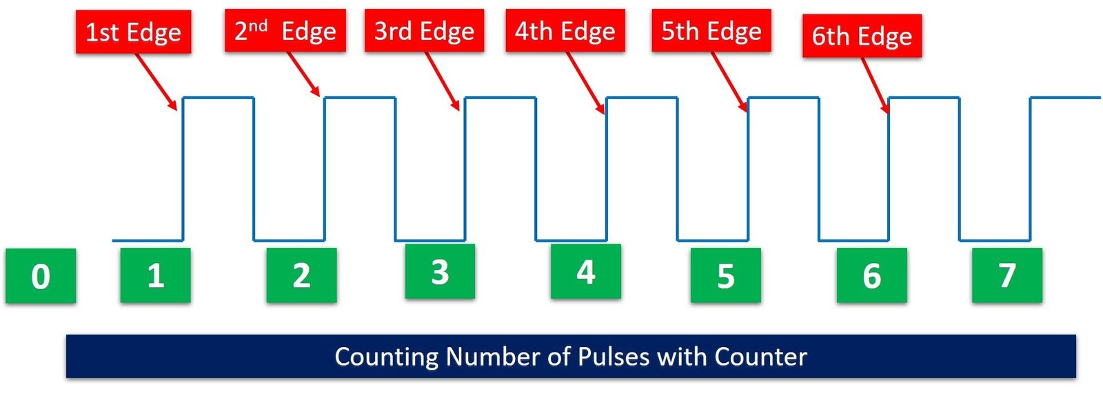
With this in mind, we can use the pulse counting method along with TM4C123 timers to count external events such as the parking system, object counter, and RPM measurement system.
RPM Measurement using TM4C123 Timer as a Counter
All things considered, now we will see an example to measure RPM of DC motor using an infrared optical sensor and TM4C123 timer as a pulse counter.
Convert RPM into Pulses
To measure motor speed, first we need to find a technique to convert motor rotation into pulse. We can measure these pulese with TM4C123 microcontroller counter. Consequetly, we can convert these measured pulses into motor speed or revolutions per minute.
Infrared Sensor Module
To convert motor rotations into pulses, we will use an infrared optical sensor as shown in the figure below:
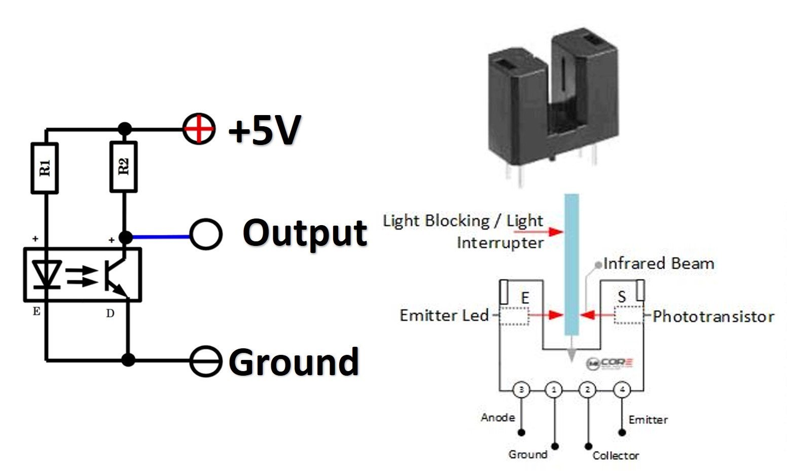
This optical sensor consists of an IR transmitter LED and an IR receiver transistor. They are placed in a parallel position to each other. Anode terminal of the IR LED is connected with 5 volts through a current limiting resistor. Similarly, the emitter terminal IR transistor is also connected with logic high through a current limiting resistor.
When there is no obstacle between IR receiver and transmitter, light transmitted by infrared LED falls directly on IR light activated transistor and IR transistor remains on. In other words, when the IR transistor is on, the output signal remains ĺactive low. On the contrary, when an obstacle comes between the IR transmitter LED and IR receiver, the transistor turns off. Also, the output signal makes a transition from active low to an active high level. Hence, a pulse or rising edge appears on the output pin. Furthermore, when an obstacle removes from the IR light transmission path, the output signal makes a transition from active high to active low and in-response produces a falling edge on the output pin.
Convert Motor rotations into Pulses
To convert motor rotations into pulses we place a black color obstacle on the motor rotor as shown in the figure below:
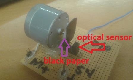
This obstacle appears between the IR transmitter and receiver path when the motor completes its one revolution. Hence, the IR obstacle sensor produces one pulse per revolution of the motor. Consequently, we can measure these pulses with TM4C123 microcontroller and so is motor speed or RPM.
Motor RPM Measurement Code TM4C123 Tiva Launchpad
This is demo code to measure motor speed using TM4C123 Tiva Launchpad timer in counter mode. This code measures the motor revolutions by counting the number of pulses for one second. After that we multiply the measured value with 60 to get revolutions per minute. Finally, it displays the value of RPM on the computer screen using the UART module of TM4C123 Tiva Launchpad. UART communication functions are developed in previous tutorial:
/* This example code measure RPM of motor using TM4C123 Timer3A as a counter */
/* Timer1A is used to create one second delay*/

/*header files for TM4C123 device and sprintf library */
#include "TM4C123GH6PM.h"
#include <stdio.h>


/*Function prototype for Timer0A and UART module initialization */
void timer1A_delaySec(int ttime);
int Timer3A_countCapture(void);
void Timer3ACounter_init(void);
void UART5_init(void);
void UART5_Transmitter(unsigned char data);
void printstring(char *str);

/* global variables to store and display pulse width or duration */
unsigned int counter;
char mesg[12];

/* main code to take RPM measurements and send data to UART terminal */

int main(void)
{
   Timer3ACounter_init();
   UART5_init();
  while(1)
	{
      TIMER3->CTL |= 1;   /* enable timer3A */
      timer1A_delaySec(1);
      counter = Timer3A_countCapture();
      TIMER3->CTL &= ~1; /* disable TIMER3A during setup */
      TIMER3->TAV = 0;
      TIMER3->TAR = 0;
      sprintf(mesg, "\r\nRPM = %d RPM", counter*60); /* convert float to string */
      printstring(mesg); /* print frequency on serial monitor*/
	}

}

/* Configure Timer3A in input-edge counter mode */
void Timer3ACounter_init(void)
{
SYSCTL->RCGCTIMER |= (1<<3);  /* enable clock to Timer Block 3  */
SYSCTL->RCGCGPIO |= (1<<1);      /* enable clock to PORTB  */

GPIOB->DIR &= ~(1<<2);        /* make PB2 an input pin */
GPIOB->DEN |= (1<<2);         /* make PB2 a digital pin */
GPIOB->AFSEL |= (1<<2);       /* enable alternate function on PB2 */
GPIOB->PCTL &= ~0x00000F00;  /* configure PB2 as T3CCP0 pin */
GPIOB->PCTL |= 0x00000700;

TIMER3->CTL &= ~(1<<0);  /* disable TIMER3A during setup */
TIMER3->CFG |= (1<<2);  /* configure as 16-bit timer mode */
TIMER3->TAMR = 0x13;        /* up-count, edge-count, capture mode */
TIMER3->TAMATCHR = 0xFFFF;  /* set the count limit */
TIMER3->TAPMR = 0xFF;	      /* to 0xFFFFFF with prescaler */
TIMER3->CTL |= ~(1<<3)|~(1<<2); /* capture the rising edge */
}

/* this routine will execute after every one second */

int Timer3A_countCapture(void)
{
    return TIMER3->TAR;
}


/* Create one second delay using Timer block 1 and sub timer A */

void timer1A_delaySec(int ttime)
{
    int i;
    SYSCTL->RCGCTIMER |= 2;     /* enable clock to Timer Block 1 */

TIMER1->CTL = 0;            /* disable Timer before initialization */
    TIMER1->CFG = 0x04;         /* 16-bit option */
    TIMER1->TAMR = 0x02;        /* periodic mode and down-counter */
    TIMER1->TAILR = 64000 - 1;  /* TimerA interval load value reg */
    TIMER1->TAPR = 250 - 1;     /* TimerA Prescaler 16MHz/250=64000Hz */
    TIMER1->ICR = 0x1;          /* clear the TimerA timeout flag */
    TIMER1->CTL |= 0x01;        /* enable Timer A after initialization */

    for(i = 0; i < ttime; i++)
    {
        while ((TIMER1->RIS & 0x1) == 0) ;      /* wait for TimerA timeout flag */
        TIMER1->ICR = 0x1;      /* clear the TimerA timeout flag */
    }
}
void UART5_init(void)
{
    SYSCTL->RCGCUART |= 0x20;  /* enable clock to UART5 */
    SYSCTL->RCGCGPIO |= 0x10;  /* enable clock to PORTE for PE4/Rx and RE5/Tx */
    /* UART0 initialization */
    UART5->CTL = 0;         /* UART5 module disbable */
    UART5->IBRD = 104;      /* for 9600 baud rate, integer = 104 */
    UART5->FBRD = 11;       /* for 9600 baud rate, fractional = 11*/
    UART5->CC = 0;          /*select system clock*/
    UART5->LCRH = 0x60;     /* data lenght 8-bit, not parity bit, no FIFO */
    UART5->CTL = 0x301;     /* Enable UART5 module, Rx and Tx */

    /* UART5 TX5 and RX5 use PE4 and PE5. Configure them digital and enable alternate function */
    GPIOE->DEN = 0x30;      /* set PE4 and PE5 as digital */
    GPIOE->AFSEL = 0x30;    /* Use PE4,PE5 alternate function */
    GPIOE->AMSEL = 0;    /* Turn off analg function*/
    GPIOE->PCTL = 0x00110000;     /* configure PE4 and PE5 for UART */
}
void UART5_Transmitter(unsigned char data)
{
    while((UART5->FR & (1<<5)) != 0); /* wait until Tx buffer not full */
    UART5->DR = data;                  /* before giving it another byte */
}

void printstring(char *str)
{
  while(*str)
	{
		UART5_Transmitter(*(str++));
	}
}

/* This function is called by the startup assembly code to perform system specific initialization tasks. */
void SystemInit(void)
{
    SCB->CPACR |= 0x00F00000;
}
Hardware Demo
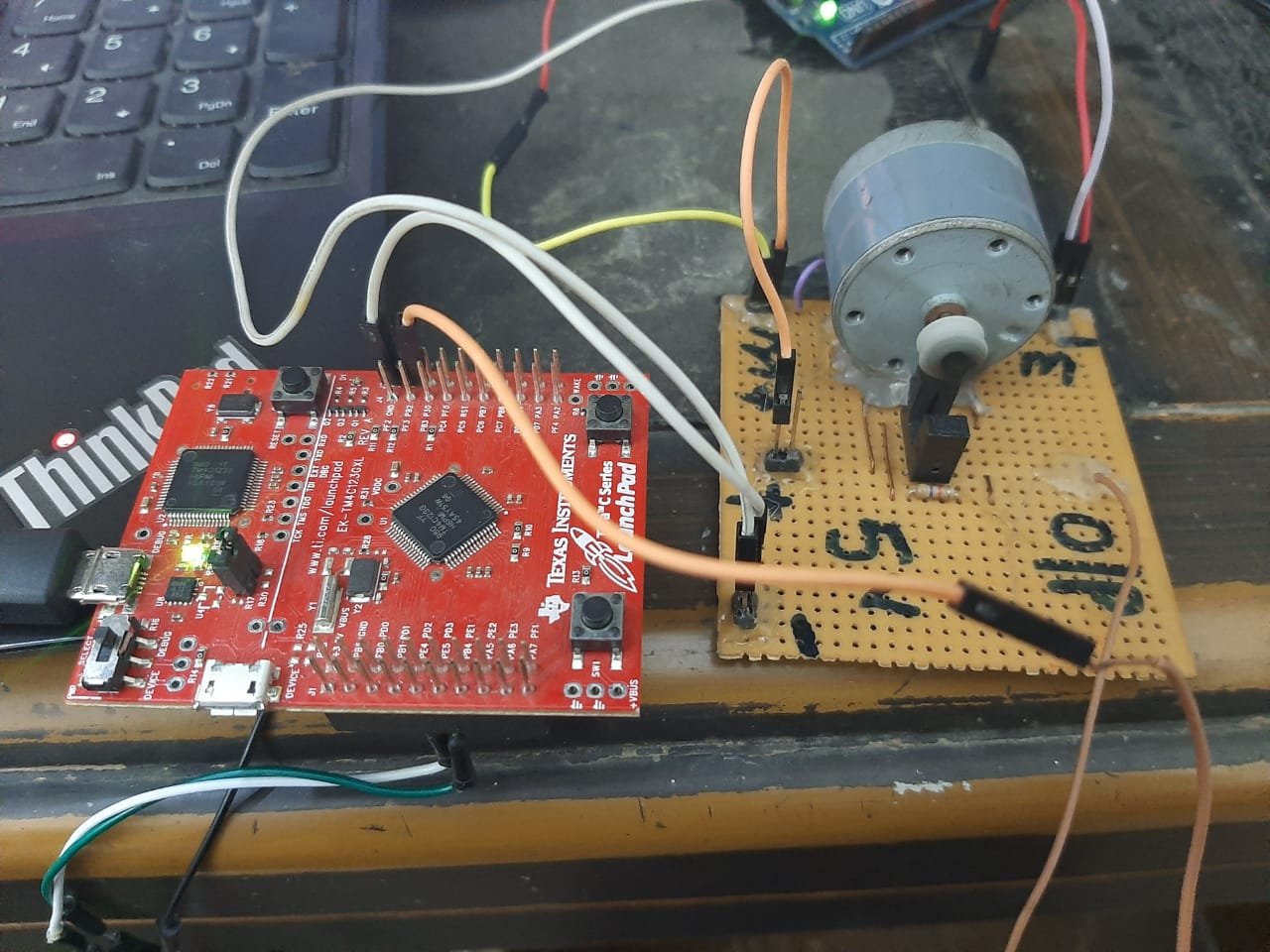
To see the output of the above code, make a connection between TM4C123 Tiva C launchpad and IR obstacle sensor according to this circuit diagram. Connect output pin of sensor to PB2 pin of Tiva board. Also, place the motor in the middle position of the sensor in such a way that black obstacle should appear in between the receiver and transmitter part of sensor once per rotation of the motor.
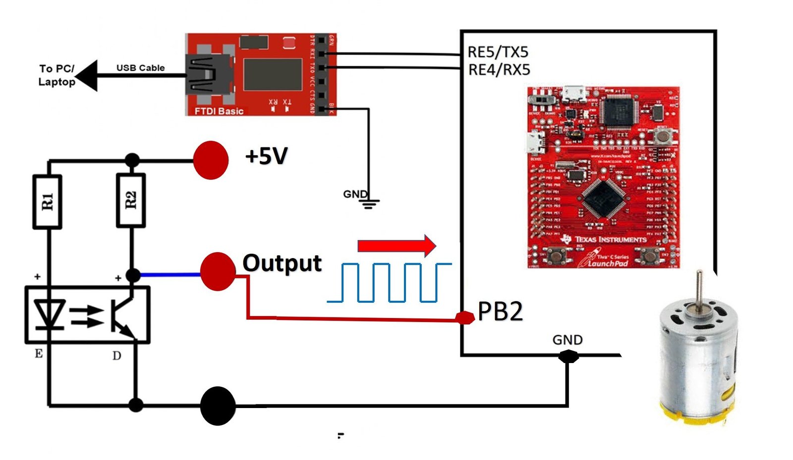
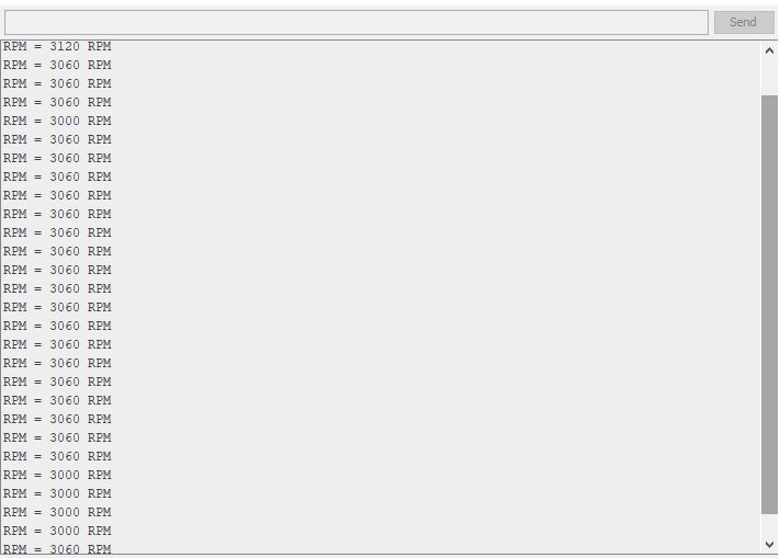
After that upload the above given code to TM4C123 Tiva C Launchpad and press the reset button. Finally, open the serial terminal on your computer by selecting the COM pin to which USB to serial converter is connected. You will get the dc motor speed in RPM on serial terminal like this:
How Code Works?
Inside the main code, first, we initialize the Timer3ACounter_init() and UART5_init(). This Timer3ACounter_init() function configures Timer3A in input-edge counter mode by selecting a positive edge as a capture event. Similarly, this UART5_init() function configures the UART5 module to transmit data from Tiva Launchpad to the computer.
Timer3ACounter_init();
UART5_init();
After that while(1) loop executes continuously with a delay of one second. Inside the while loop, first enable the Timer3A and it will start to count on each occurrence of rising edge.
TIMER3->CTL |= 1; /* enable timer3A */This line adds the delay of one second using Timer1A. The reason this delay of second is added. Because we want to count the number of pulses or motor rotation for one second. Hence, Timer3A counter will count the number of pulses for one second.
timer1A_delaySec(1); /* wait for one second */Now, we call the Timer3A_countCapture() function to read the counter value from Timer3A->TAV register and save the current value of Timer3A->TAV register inside the “counter” variable.
counter = Timer3A_countCapture();Disable the Timer 3A counter and reset the counter value to zero.
 TIMER3->CTL &= ~1;   /* disable TIMER3A during setup */
 TIMER3->TAV = 0;
  /*reset counter value to zero */
 TIMER3->TAR = 0;  /*reset counter value to zero */
Convert the counter variable value into a string using sprintf() function and transmit to the computer using printstring() routine. We multiply the counter value to 60 to convert revolution per second into RPM.
sprintf(mesg, "\r\nRPM = %d RPM", counter*60); /* convert float to string */
printstring(mesg); /* print frequency on serial monitor*/
Video Demo
Summary
In conclusion, by configuring the TM4C123 timers in input-edge counter mode, we can effectively use the microcontroller as an RPM meter, also known as a tachometer. This tutorial demonstrated how to count external events triggered by an infrared optical sensor to measure the rotational speed of electromechanical systems. The flexibility of the TM4C123 timers makes them ideal for designing accurate and reliable RPM measurement systems, which are crucial in various industrial and automotive applications.
Other TM4C123 Timer Tutorials:
- Frequency Measurement using TM4C123 Timers in Input-Edge Capture Mode
- TM4C123 Timer in Input Edge Time Mode – Pulse Duration Measurement
- Timer Interrupt TM4C123 – Generate Delay with GPTM Interrupt Service Routine
- SysTick Timer (System Timer) TM4C123G ARM Cortex M4 Microcontroller
- Systick Timer Interrupt Programming TM4C123 ARM Cortex M4
- GPIO Interrupts TM4C123 Tiva Launchpad – External Interrupts
Related Projects:
Hi
Can you please do it as a timer interrupt