This tutorial is on pulse width or pulse duration measurement using TM4C123 microcontroller programmable Timer block. In this tutorial, we will use the basic Timer block in input edge time mode to capture rising and falling edges of pulses. For demonstration purposes, we will provide a pulse signal to one of the capture pins of TM4C123 Tiva Launchpad from an external source such as Arduino.
After reading this tutorial, you will learn the followings:
- Use programmable general purpose timer blocks of TM4C123 microcontroller.
- Configure Timer Blocks of TM4C123 in capture input edge timer mode.
- Learn to capture timers on the rising edge, falling edge and both edges.
- Able to measure pulse width or duration of any digital signal
Pre-requisites:

- How to Download and Install Keil uVision for ARM and 8051
- Getting started with Keil uVision: Write your first Program for Tiva LaunchPad
TM4C123 Timers Input edge time capturing Mode
In input edge time capture mode, the TM4C123 microcontroller general purpose timers can be configured to measure time between events. If the timer is configured in down count mode, it starts down counting based on the value loaded in the GPTMTnILR and GPTMTnPR registers. On the contrary if the timer is initialized in up count mode, it starts counting from 0x0 and up to its maximum count value. Once initialized and enabled, timer keeps counting from its start value.
All timer blocks can be used with GPIO pins to detect external events by using timers in capture mode.They can detect three types of events on GPIO pins such as rising edge, falling edge or both. The following table shows the input capture GPIO pins for each timer block.
Whenever an input event is detected on a respective timer GPIO pin, the content of the timer counter saved into GPTMTAR register and counter keeps counting. We can save the time value of timer using either GPTMTAR (for TimerA ) or GPTMTBR (for TimerB) registers. Bit4 of GPTMRIS register becomes one, whenever an edge is detected on a GPIO pin. GPTMRIS register bit4 automatically sets high based on edge settings such as ising edge, falling edge or both.
How to Measure Pulse Duration using TM4C123 Timers
For example, by measuring the time difference between the rising and falling edge of any PWM signal, we can measure its pulse width or pulse duration. In order to do so, when an event occurs on a GPIO pin due to a rising edge signal, saves the content of the GPTMTAR register in one variable. After a rising edge, there will always be a falling edge of the pulse. Hence, when the GPIO pin captures the falling edge, saves the content of GPTMTAR into another variable. Now the time difference of these two values will give us the pulse duration.

If the time period of the PWM signal is known, you can also find its pulse width by dividing pulse duration with the timer period as shown in figure below:

Note: The timer period of any digital signal can also be measured with TM4C123 timers by measuring the difference between two consecutive positive edges or falling edges.
Configure TM4C123 Timer in input-edge Timer Mode
In this tutorial, we will be using Timer0 block and subtimer A.
Enable Clock and Configure GPIO Pin
To initialize TM4C123 Tiva series microcontroller Timer0A in input-edge time mode, first enable the clock to Timer0A using RCGCTIMER register. Setting Bit0 enables the system clock to Timer0A.
SYSCTL->RCGCTIMER |= 1; /* enable clock to Timer Block 0 */In input-edge timer capture mode, the GPIO pin PB6 of PORTB is used to capture external signals. Also, enable the clock to PORTB by setting bit2 of RCGCGPIO register.
SYSCTL->RCGCGPIO |= 2; /* enable clock to PORTB */These lines configure the PB6 GPIO pin as a digital input pin and select alternate function of PB6 as Timer0A input pin. If you don’t know how to configure GPIO pins of TM4C123 Tiva C Launchpad, you can read our previously posted in-depth tutorials:
 GPIOB->DIR &= ~(1<<6);        /* make PB6 an input pin */
 GPIOB->DEN |= (1<<6);         /* make PB6 as digital pin */
 GPIOB->AFSEL |= (1<<6);       /* use PB6 alternate function */
 GPIOB->PCTL &= ~0x0F000000;  /* configure PB6 for T0CCP0 */
 GPIOB->PCTL |= 0x07000000;
Initialize Timer0A in Input Edge Timer Capture Mode
Before initialization of timer registers, it is recommended to disable the timer. Hence, this line disables the Timer0A by clearing TAEN bit of GPTMCTL register.
TIMER0->CTL &= ~(1<<0); /* disable timer0A during setup */GPTMCFG configures the selected timer in 16-bit or 32-bit mode. For input-edge time mode, all timers can only be used separately and timers concatenated feature does not work. Therefore, we select the Timer0A in 16-bit configuration mode.
TIMER0->CFG = 4; /* Timer0A in 16-bit timer mode */Timer mode select register (TAMR) is used to select timer mode such as one-shot, periodic and capture mode.Moreover, capture mode also has two further modes such as input-edge time and input-edge counter mode. Furthermore, it is also used to configure up-counting and down counting mode. This line configures Timer0A in up-count , capture and input edge time mode by setting TAAMS, TACMR, TAMR and TACDIR bits of GPTMTAMR register.
TIMER0->TAMR = 0x17; /* Timer0A enable up-count, capture mod, input edge time mode*/The final configuration is to select input capture signal settings from three possible options that are rising, falling or both edges. Bits 2 and 3 (TAEVENT) of GPTMCTL control register are used to configure Timer0A event mode. Setting bits 2 and 3 of GPTMCTL selects both negative and positive edges as capture events.
TIMER0->CTL |= (1<<3)|(1<<2); /* capture rising and falling edges on PB6 pin */Setting bit0 of GPTMCTL register enables the Timer0A and it starts counting.
TIMER0->CTL |= (1<<0); /* enable Timer0A */By combining all above initialization statements, we create a function named “Timer0ACapture_init()”.
void Timer0ACapture_init(void)
{
    SYSCTL->RCGCTIMER |= 1;     /* enable clock to Timer Block 0 */
    SYSCTL->RCGCGPIO |= 2;      /* enable clock to PORTB */

    GPIOB->DIR &= ~(1<<6);        /* make PB6 an input pin */
    GPIOB->DEN |= (1<<6);         /* make PB6 as digital pin */
    GPIOB->AFSEL |= (1<<6);       /* use PB6 alternate function */
    GPIOB->PCTL &= ~0x0F000000;  /* configure PB6 for T0CCP0 */
    GPIOB->PCTL |= 0x07000000;

    TIMER0->CTL &= ~(1<<0);          /* disable timer0A during setup */
    TIMER0->CFG = 4;            /* Timer0A in 16-bit timer mode */
    TIMER0->TAMR = 0x17;        /* Timer0A enable up-count and capture mode */
    TIMER0->CTL |= (1<<3)|(1<<2);   /* capture rising and falling edges on PB6 pin */
    TIMER0->CTL |= (1<<0);           /* enable Timer0A */
}
Pulse Duration Measurement Function
This function captures consecutive rising and falling edges of a periodic signal with Timer0A and returns the time difference. Inside this Timer0ACapture_PulseWidth() function, first we clears the timer0A capture flag.
TIMER0->ICR = 4; /* clear timer0A capture flag */After that we keep polling the status of the CAERIS bit of GPTMRIS register which indicates that a capture mode event has occurred for Timer0A. The CAERIS bit flat of GPTMRIS sets to 1 whenever an event occurred on PB6 pin for Timer0A in capture mode. Hence, TM4C123 microcontroller execution keeps waiting in this loop till the event is captured on a PB8 pin.
while((TIMER0->RIS & (1<<2)) == 0) ; /* wait till captured */After the capture event occurs, the condition inside the above statement becomes false and TM4C123 microcontroller starts to execute this ‘if’ condition. This ‘if’ condition checks whether this event was due to a rising edge. The logic high state of PB6 pin identifies that the previously detected edge was rising edge. If it was a rising edge and TM4C123 starts to execute statements inside the ‘if’ block.
if(GPIOB->DATA & (1<<6)) /*check if rising edge occurs */Otherwise, it again starts to execute the while loop and waits till an event occurs.
If previous event was a rising edge that means if condition becomes true, we save the counter value in fallingEdge variable followed by the clear of Timer0A capture flag.
risingEdge = TIMER0->TAR;     /* save the timestamp */
TIMER0->ICR = 4;            /* clear timer0A capture flag */
After that TM4C123 microcontroller again waits for the falling edge to occur using this while statement.
while((TIMER0->RIS & (1<<2)) == 0) ; /* wait till captured */This time, we do not need to check whether this event will occur due to falling edge or not. Because, a falling edge is always followed by a rising edge. When a falling edge occurs, save the content of the counter register into another variable “fallingEdge”.
fallingEdge = TIMER0->TAR; /* save the timestamp */At the end, Tiva C microcontroller takes the difference of two timestamps and returns the value to the caller.
return (fallingEdge - risingEdge) & 0x00FFFFFF; /* return the time difference */This difference will give the pulse duration in terms of number of clocks. In order to get pulse duration in the time domain, multiply the measured time difference value with the inverse of the operating frequency of Timer that is 16MHz.
width = (time_period * 62.5)/1000000; // convert the number of clocks to timetime_period = Timer0ACapture_PulseWidth(); Hence, this Timer0ACapture_PulseWidth() routine can be called inside the main code to measure pulse duration.
/* This function captures consecutive rising and falling edges of a periodic signal from Timer Block 0 Timer A and returns the time difference (the period of the signal). */
int Timer0ACapture_PulseWidth(void)
{
    int risingEdge, fallingEdge;
	while(1)
	{
    TIMER0->ICR = 4;            /* clear timer0A capture flag */
    while((TIMER0->RIS & (1<<2)) == 0) ;    /* wait till captured */
	  if(GPIOB->DATA & (1<<6)) /*check if rising edge occurs */
		{
    risingEdge = TIMER0->TAR;     /* save the timestamp */
    TIMER0->ICR = 4;            /* clear timer0A capture flag */
    /* detect falling edge */
    while((TIMER0->RIS & (1<<2)) == 0) ;    /* wait till captured */
    fallingEdge = TIMER0->TAR;     /* save the timestamp */
    return (fallingEdge - risingEdge) & 0x00FFFFFF; /* return the time difference */
		}
	}
}
Code of TM4C123 Timer in input-edge Time Capture Mode
This example code of Tiva C microcontroller measures the pulse duration of digital signal given to PB6 pin of Tiva C Launchpad. It also sends the measured pulse duration to computer through UART5 module of TM4C123GH6PM microcontroller. The UART functions used in the code are developed in previous tutorial available here:
This example code is written using Keil uvision.
/* This example code can measure the pulse width or pulse duration of a wave signal */
/* Timer block 0 and sub timer A is configured in capture mode with both +ve and -ve edges detection */

/*header files for TM4C123 device and sprintf library */
#include "TM4C123GH6PM.h"
#include <stdio.h>

/*Function prototype for Timer0A and UART module initialization */

int Timer0ACapture_PulseWidth(void);
void Timer0ACapture_init(void);
void Delay(unsigned long counter);
void UART5_init(void);
void UART5_Transmitter(unsigned char data);
void printstring(char *str);

/* global variables to store and display pulse width or duration */
unsigned int time_period;
char mesg[12];

/* main code to take pulse duration measurement and send data to UART terminal */
float width;
int main(void)
{
	 Timer0ACapture_init();
	 UART5_init();
	while(1)
	{
		  time_period = Timer0ACapture_PulseWidth();
		  width = (time_period * 62.5)/1000000;
		  sprintf(mesg, "\r\nPulse width = %f ms", width);
			printstring(mesg);
      Delay(1000);
	}

}

void Timer0ACapture_init(void)
{
    SYSCTL->RCGCTIMER |= 1;     /* enable clock to Timer Block 0 */
    SYSCTL->RCGCGPIO |= 2;      /* enable clock to PORTB */

    GPIOB->DIR &= ~(1<<6);        /* make PB6 an input pin */
    GPIOB->DEN |= (1<<6);         /* make PB6 as digital pin */
    GPIOB->AFSEL |= (1<<6);       /* use PB6 alternate function */
    GPIOB->PCTL &= ~0x0F000000;  /* configure PB6 for T0CCP0 */
    GPIOB->PCTL |= 0x07000000;

    TIMER0->CTL &= ~(1<<0);          /* disable timer0A during setup */
    TIMER0->CFG = 4;            /* Timer0A in 16-bit timer mode */
    TIMER0->TAMR = 0x17;        /* Timer0A enable up-count and capture mode */
    TIMER0->CTL |= (1<<3)|(1<<2);   /* capture rising and falling edges on PB6 pin */
    TIMER0->CTL |= (1<<0);           /* enable Timer0A */
}

/* This function captures consecutive rising and falling edges of a periodic signal from Timer Block 0 Timer A and returns the time difference (the period of the signal). */
int Timer0ACapture_PulseWidth(void)
{
    int risingEdge, fallingEdge;
	while(1)
	{
    TIMER0->ICR = 4;            /* clear timer0A capture flag */
    while((TIMER0->RIS & (1<<2)) == 0) ;    /* wait till captured */
	  if(GPIOB->DATA & (1<<6)) /*check if rising edge occurs */
		{
    risingEdge = TIMER0->TAR;     /* save the timestamp */
		/* detect falling edge */
    TIMER0->ICR = 4;            /* clear timer0A capture flag */
    while((TIMER0->RIS & (1<<2)) == 0) ;    /* wait till captured */
    fallingEdge = TIMER0->TAR;     /* save the timestamp */
		return (fallingEdge - risingEdge) & 0x00FFFFFF; /* return the time difference */
		}
	}
}
void UART5_init(void)
{
	  SYSCTL->RCGCUART |= 0x20;  /* enable clock to UART5 */
    SYSCTL->RCGCGPIO |= 0x10;  /* enable clock to PORTE for PE4/Rx and RE5/Tx */
    Delay(1);
    /* UART0 initialization */
    UART5->CTL = 0;         /* UART5 module disbable */
    UART5->IBRD = 104;      /* for 9600 baud rate, integer = 104 */
    UART5->FBRD = 11;       /* for 9600 baud rate, fractional = 11*/
    UART5->CC = 0;          /*select system clock*/
    UART5->LCRH = 0x60;     /* data lenght 8-bit, not parity bit, no FIFO */
    UART5->CTL = 0x301;     /* Enable UART5 module, Rx and Tx */

    /* UART5 TX5 and RX5 use PE4 and PE5. Configure them digital and enable alternate function */
    GPIOE->DEN = 0x30;      /* set PE4 and PE5 as digital */
    GPIOE->AFSEL = 0x30;    /* Use PE4,PE5 alternate function */
    GPIOE->AMSEL = 0;    /* Turn off analg function*/
    GPIOE->PCTL = 0x00110000;     /* configure PE4 and PE5 for UART */
}
void UART5_Transmitter(unsigned char data)
{
    while((UART5->FR & (1<<5)) != 0); /* wait until Tx buffer not full */
    UART5->DR = data;                  /* before giving it another byte */
}

void printstring(char *str)
{
  while(*str)
	{
		UART5_Transmitter(*(str++));
	}
}
void Delay(unsigned long counter)
{
	unsigned long i = 0;

	for(i=0; i< counter*1000; i++);
}
/* This function is called by the startup assembly code to perform system specific initialization tasks. */
void SystemInit(void)
{
    __disable_irq();    /* disable all IRQs */

    /* Grant coprocessor access */
    /* This is required since TM4C123G has a floating point coprocessor */
    SCB->CPACR |= 0x00F00000;
}
Demo
To see the demo and working of the above code, we will connect the PWM signal with variable duty cycle to the PB6 pin of TM4C123 Tiva Launchpad. As we mentioned earlier, PB6 is a capture pin for Timer0A. To provide variable PWM duty cycle to Tiva Launchpad, we use an Arduino Uno.
Schematic Diagram
Now make connection with TM4C123 Tiva Launchpad and Arduino according to this schematic diagram. Also, make sure to connect ground terminals of TM4C123 and Arduino with each other.
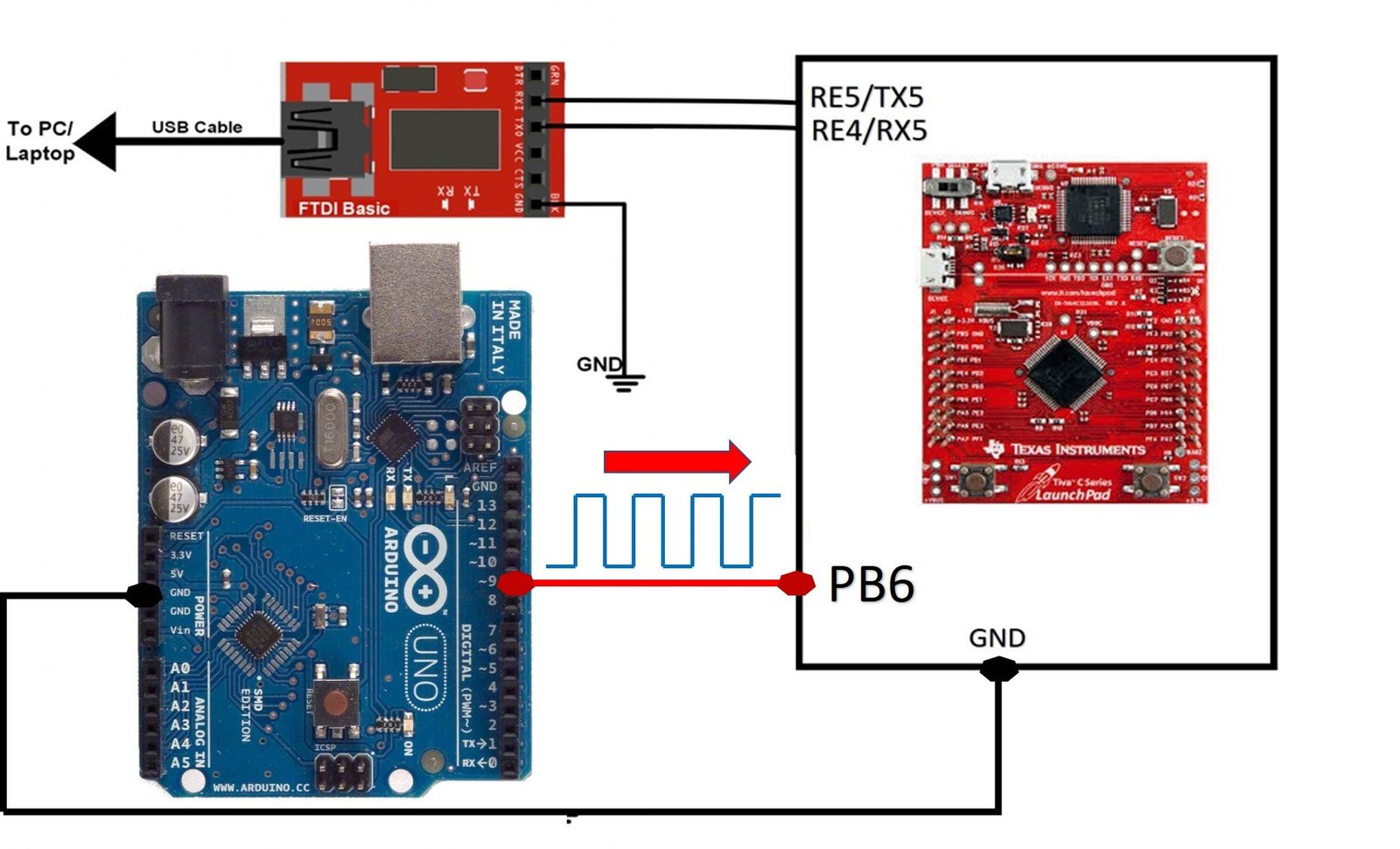
By default Arduino generates a 496Hz PWM signal. That means the time period of the Arduino default PWM signal is 2.016 millisecond. For example, if the duty cycle of PWM cycle is 50% that means the pulse duration or on time will be 1.008 ms almost. Similarly, if the duty cycle is 0%, pulse duration will be zero and if duty cycle is 100%, pulse duration will be equal to time period. If you don’t know about PWM and its related terminologies, you can read this post:
This Arduino Code generates a variable duty cycle PWM from 0 to 100% duty cycle and output of PWM appears on pin 9 of Arduino. Upload this code to Arduino using Arduino IDE.
int ledPin = 9;      // LED connected to digital pin 9
int analogPin = 3;   // potentiometer connected to analog pin 3
int val = 0;         // variable to store the read value

void setup() {
  pinMode(ledPin, OUTPUT);  // sets the pin as output
}

void loop() {
  for (int i=0; i<255; i++)
{
  analogWrite(ledPin, i); // analogRead values go from 0 to 1023, analogWrite values from 0 to 255
  delay(200);
}
}
Now, provide this output signal to TM4C123 microcontroller through PB6 pin and observe the output of this program on the serial monitor. You will see that the pulse duration measurement output on the serial monitor. Hence, the time of measured pulse duration keeps increasing as the pulse width of the PWM signal increases. Furthermore, pulse width of the PWM signal is controlled through the above Arduino code. After you upload the code to Arduino, select the COM pin to which USB to Serial converter is connected through the UART5 module of TM4C123 MCU. After that, open the serial monitor, you will get output like this:

Video Demo
Summary:
In this tutorial, we learned how to measure pulse width using timer of TM4C123 in input edge time mode. By following this tutorial, you can measure pulse width of square wave signals in your projects. This tutorial covers pulse width or pulse duration measurement using the TM4C123 microcontroller’s programmable Timer block. It explains how to use the basic Timer block in input edge time mode to capture the rising and falling edges of pulses. For demonstration, an external pulse signal from a source like an Arduino is provided to one of the TM4C123 Tiva Launchpad’s capture pins.
Other TM4C123 Tiva Launchpad Tutorials:
- Timer Interrupt TM4C123
- GPIO Interrupts TM4C123 Tiva Launchpad
- ADC TM4C123G Tiva C Launchpad
- MPU6050 Gyroscope Accelerometer sensor interfacing with TM4C123G
- I2C Communication TM4C123G Tiva C
Other Related Tutorials:
Interesting. Is it not surprising that the pulse increases by an almost constant 0.0155 ms (+/-) , in the given output ? The Arduino’s clock would heat and so have a hard time to be constant? or you see another reason for this repetitive pattern?
This is not the case. If you see TM4C123 MCU code, inside the main function, TM4C123 takes the measurement of time between rising and falling edges after every one second, so it will not be an issue for TM4C123 and for Arduino, we used it just for a demo as an input pulse signal for TM4C123 timer capture signal. Maybe it will create an issue if we use it for a longer time.
Ok, when you wrote “Furthermore, pulse width of the PWM signal is controlled through the above Arduino code. You will get output like this:”, the following output was nothing else than a “like this” and not what you got, for real.
Was the pulse width tested against a measure from an oscilloscope?
Yes, I did. If you connect a digital oscilloscope with the D9 pin of Arduino, you will get a PWM signal starting from 0% duty cycle up to 100% duty cycle. The output of the serial monitor shows the pulse duration time and nothing else.
Tiva board can read upto how much freq at wide timer 0 ?
I am not sure this code working correctly (especially UART code, it doesn’t work any topic about UART), when I build project with SystemInit, I get an error, then when I make comment line to SystemInit, the output have been shown meaningless characters for Putty, RealTerm and Arduino Serial Port.
Hi,
For UART, you are getting garbage values on the serial monitor, because we have not selected the crystal frequency properly. Make sure to select the correct crystal frequency from the project configuration page. The SystemInit() function need to be called if you are using Keil vision 4 or any version less than Keil vision 5.
Can you try this project with Keil vision 4?
It worked at Keil vision 4, thank you.
I am glad it helped.
Hi,
Very much Informative.
I need one help. How to configure Timer0 in 32 bit Mode.
I tried TIMER0->CFG = 0 (Instead of TIMER0->CFG = 4). If I Change this line
nothing I get on Serial monitor.
Pl Can You Help me out.
Thanks & Regards,
Ravi
Timer0 and Timer2, on the Arduino UNO, are 8 bits (0 to 255), Timer1 is 16 bits. Maybe there is a special version with a 32 bits mode, but the (standard) Arduino, the Arduino UNO, does not seem to have one. At least, as far as I remember.
Hi,
I changed the above code for TIMER0 & T0CCP1. Unfortunately it is not working. Pl can any one through the Light..
/* This example code can measure the pulse width or pulse duration of a wave signal */
/* Timer block 0 and sub timer A is configured in capture mode with both +ve and -ve edges detection */
/*header files for TM4C123 device and sprintf library */
#include “TM4C123GH6PM.h”
#include
/*Function prototype for Timer0A and UART module initialization */
int Timer0BCapture_PulseWidth(void);
void Timer0BCapture_init(void);
void Delay(unsigned long counter);
void UART5_init(void);
void UART5_Transmitter(unsigned char data);
void printstring(char *str);
/* global variables to store and display pulse width or duration */
unsigned int time_period;
char mesg[12];
/* main code to take pulse duration measurement and send data to UART terminal */
float width;
int main(void)
{
//SYSCTL_SYSDIV_2_5
//SysCtlClockSet(SYSCTL_SYSDIV_2_5|SYSCTL_USE_PLL|SYSCTL_XTAL_16MHZ|SYSCTL_OSC_MAIN);
// This line sets the clock at 80 Mhz
Timer0BCapture_init();
UART5_init();
while(1)
{
time_period = Timer0BCapture_PulseWidth();
width = (time_period * 62.5)/1000000;
sprintf(mesg, “\r\nPulse width = %f ms”, width);
printstring(mesg);
Delay(1000);
}
}
void Timer0BCapture_init(void)
{
SYSCTL->RCGCTIMER |= 1; /* enable clock to Timer Block 0 */
SYSCTL->RCGCGPIO |= 2; /* enable clock to PORTB */
GPIOB->DIR &= ~(1<DEN |= (1<AFSEL |= (1<PCTL &= ~0xF0000000; /* configure PB7 for T0CCP1 */
GPIOB->PCTL |= 0x70000000;
TIMER0->CTL &= ~(1<CFG = 4; /* Timer0A in 16-bit timer mode */
TIMER0->TBMR = 0x17; /* Timer1B enable up-count and capture mode */
TIMER0->CTL |= (1<<0x11)|(1<CTL |= (1<ICR = 0x40; /* clear timer0B capture flag */ //CAECINT GPTM Timer A Capture Mode Event Interrupt Clear
// while((TIMER0->RIS & (1<DATA & (1<TBR; /* save the timestamp */
/* detect falling edge */
TIMER0->ICR = 0x40; /* clear timer0B capture flag */
while((TIMER0->RIS & (1<TBR; /* save the timestamp */
return (fallingEdge – risingEdge) & 0x00FFFFFF; /* return the time difference */
}
}
}
void UART5_init(void)
{
SYSCTL->RCGCUART |= 0x20; /* enable clock to UART5 */
SYSCTL->RCGCGPIO |= 0x10; /* enable clock to PORTE for PE4/Rx and RE5/Tx */
Delay(1);
/* UART0 initialization */
UART5->CTL = 0; /* UART5 module disbable */
UART5->IBRD = 104; /* for 9600 baud rate, integer = 104 */
UART5->FBRD = 11; /* for 9600 baud rate, fractional = 11*/
//UART5->IBRD = 8750; /* for 9600 baud rate, integer = 104 */
UART5->CC = 0; /*select system clock*/
UART5->LCRH = 0x60; /* data lenght 8-bit, not parity bit, no FIFO */
UART5->CTL = 0x301; /* Enable UART5 module, Rx and Tx */
/* UART5 TX5 and RX5 use PE4 and PE5. Configure them digital and enable alternate function */
GPIOE->DEN = 0x30; /* set PE4 and PE5 as digital */
GPIOE->AFSEL = 0x30; /* Use PE4,PE5 alternate function */
GPIOE->AMSEL = 0; /* Turn off analg function*/
GPIOE->PCTL = 0x00110000; /* configure PE4 and PE5 for UART */
}
void UART5_Transmitter(unsigned char data)
{
while((UART5->FR & (1<DR = data; /* before giving it another byte */
}
void printstring(char *str)
{
while(*str)
{
UART5_Transmitter(*(str++));
}
}
void Delay(unsigned long counter)
{
unsigned long i = 0;
for(i=0; i< counter*1000; i++);
}
Hi,
I am working on a project for Frequency & Duty Cycle Measurement for the range of frequency from 1 Hz to 10000 Hz & also Duty Cycle.
I tried the Code Provided here for Frequency & Pulse duration Measurement.
it is working ok. but I am looking for the same with Timer Interrupt Based.
Request to provide the Code for the same.
Pl Can You Help me out.
Thanks & Regards,
Ravi
I am NOT the author of the article, but a Timer interruption fires when a given count reaches a value from a given state (as example, when a countdown which would be at the value 1 goes down to the value of 0; that is JUST an example). On the other hand, a pulse width is measured when a voltage is at a given value and then moves (to a larger or smaller value, generally with some hysteresis) which then fires an interruption from the IO pin under monitoring. And in that interruption handler, you read the value of a clock or of a timer.
I fail to see how someone would base a duty cycle precise measurement basing the interrupt on a timer. It is like sitting at a traffic light control, but looking at exactly each 120 seconds, for a nanosecond, if the traffic light is now green, to compute how long the traffic light stayed red. I would rather base my computation on the interruption generated by the light switching from red to green, isn’t it? Or I just don’t understand what you are trying to do.
And once again, I repeat myself, but I am not the author of the original article.
Hi,
Thanks for the Reply.
Example provided works fine. But It is Blocking MCU Time.
Hope u got my problem.
Dear Sir
Where to get the TM4C123GH6PM.h library i have “tm4c123gh6pm.h”. Without that header code shows error.
Thank you