UC2842 belongs to a UCx84x family of integrated circuits. We can use it in Off-line and DC to DC converter applications. Additionally, it performs a current-mode PWM controller having a fixed frequency. It allows temperature range options, hysteresis ranges and choice of turn-on and turnoff thresholds. UC2842 has a PWM comparator that controls the current circuits. The operating temperature range for this IC is from –40°C to 85°C. Furthermore, it provides low- voltage locking, very small starting current and an error amplifier for precision. In summary, it has all built-in components to design ac-dc or dc-dc convert projects.
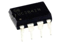
UC2842 Pinout Diagram
UC2842 PWM controller originally consists of 8 pins. However, it comes with different pin packages such as 8, 14 and 20 pin packages. But only 8 pins make this current mode PWM controller operational. This diagram describes the pinout diagram.

Pin Configuration Working
In this section, we will list the description of UC2842 IC along with its pin configuration.
| Pin Number | Pin Name | Description |
|---|---|---|
| 1 | COMP (Compensation) | An output pin responsible for external loop compensation. |
| 2 | (Voltage Feedback) | The input signal applied at the inverting terminal of the error amplifier. This input provides through a resistor divider connected to a switching power supply. |
| 3 | ISENSE (Current Sense) | Connect this pin to the current sensing resistor. Current sensing is used to check the current in the circuit. The output voltage across current sensing resistor provides to this input. The PWM terminates the OUTPUT switch conduction using this input signal. |
| 4 | (Timing Resistor/Timing Capacitor) | This pin sets the switching frequency of an internal oscillator. We just connect a timing resistor Rt to pin4 and timing capacitor Ct to GND. |
| 5 | GROUND | Connect to the ground of power supply |
| 6 | OUTPUT | It generates a PWM signal which is used to directly drive the gate of a power MOSFET. Totem pole configuration provides a high current sink and source ability. |
| 7 | (Voltage Supply) | This is connected to the positive pin of power supply. |
| 8 | (Reference Voltage) | It provides charging current for capacitor CT through resistor RT. It has short circuit protection and can provide 20 mA (in excess) for powering additional control system circuitry. |
Features of UC2842
- Current-Mode PWM controller having automatic feed-forward compensation.
- The operating voltage range is 12V to 28V.
- Low Startup (< 1 mA) and Operating Current but the current at the output pin is 200mA.
- High-Current Totem-Pole Output
- Enhanced Load-Response Characteristics
- Maximum Duty cycle is 100%
- For precise Duty cycle Control, Oscillator Discharge Current is trimmed.
- Latching PWM for Pulse−By−Pulse Current Limiting
- Operating switching Frequency of 500 kHz
- Operating Supply Current:25 mA
Alternative PWM Controller Options
UC1842, UC3842, UC1843, UC3845, UC1845
Equivalent
Where to use UC2842?
The UC2842 IC is a high-speed PWM with a switching frequency of up to 500 kHz. It has an amplifier. Therefore, you can use this IC in designing isolated and non-isolated power supply. If you require a wide temperature range in any project or application, then you can use this IC. It is ideally suited in off−line converter applications due to large hysteresis and low startup current.
How to use it?
UC2842 is available in an 8−pin DIP package as well as the 14−pin SOIC package. SOIC package has separate power and ground pins. The simplified block diagram is shown below. Pin numbers shown in parenthesis are for the SOIC-14 package.

Modes of Operation
This IC can be used in two modes which are peak current or voltage control. In peak current mode, the controller regulates the converter’s peak current and duty cycle which through error amplifier and external feedback circuitry whereas in the latter mode, the controller regulates the power converter’s duty cycle.
UCC2842 Connection Diagram Details
VCC pin is connected to a power supply whose voltage should be in a range of 12V to 28V. Vref is provided for charging timing capacitors through a timing resistor by providing charging current. The reference voltage should be grounded with a ceramic capacitor. The minimum value of this capacitor should be 0.1uF. It is very important for reference stability therefore it should be connected as close to the pin as possible.
The output pin is connected to the gate of MOSFET. The Voltage feedback is responsible for controlling a PWM signal based on the feedback. The change in current through the circuit monitored by shunt resistance. The voltage difference across this resistor is provided to the feedback pin. VFB lead length and stray capacitance should be kept as small as possible for acquiring the best stability.
How to set Frequency?
Pin four Ct/Rt is a crystal oscillator timing fixing pin. We can a network of a resistor and a capacitor across this pin. The values of Rt and Ct define the frequency of an oscillator. This mathematical relation defines relationship between timing capacitor, timing resistor, and frequency. 7
FOSC =1.72/(Rt × Ct)
We can choose any practically available values of resistor and capacitor. But the maximum operating frequency of UC2842 is 50KHz.
UC2842 Circuit Examples
In this section, we will see a few practical examples of the UC2845 PWM Controller.
Simple test Circuit
This is a circuit diagram of a test circuit. We use it to test IC outputs and internal circuits. Two potentiometers adjust the time period of PWM. Just play with these two variable resistors. After that, we will get different duty cycle PWM at the output pin.

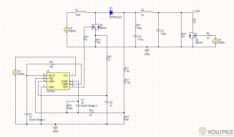
Boost Converter Circuit Example
In this boost converter circuit, UC2842 provides a PWM control signal to IRF350 MOSFET.
Applications
- Switching Regulators
- Load machines
- transformer-coupled DC-DC Converters
- Battery drain circuit
- Isolated and non-isolated power supply designs
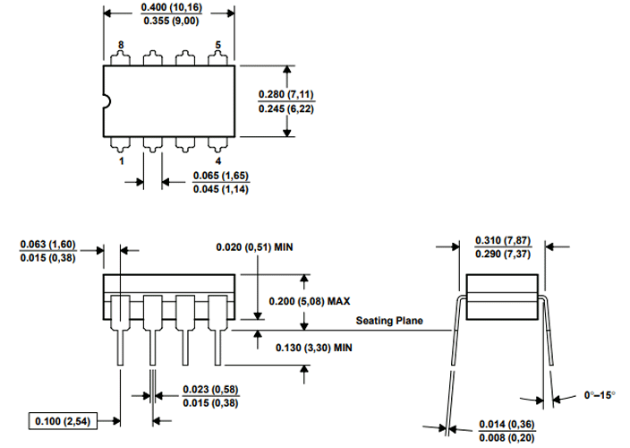
UC2842 2D Diagram
This picture explains a 2D physical dimension diagram of the 8-pin DIP package. We regularly require a dimension diagram for PCB designing. If you are looking for a dimension diagram of other packages, refer to the datasheet.