Bluetooth Controlled Robot: This project is used to control robot motion using Bluetooth and android application. User send control commands from android app to Bluetooth which is connected with pic microcontroller. Microcontroller receives commands from Bluetooth and take respective actions to drive two motor. These two motors are connected with microcontroller through motor driver integrated circuit called L298N. Bluetooth Controlled Robot involved building a robot that can receive commands via Bluetooth and then execute those commands. An Android app was used to send the commands via Bluetooth. Commands were received by Bluetooth module connected to microcontroller and the microcontroller then executed those commands.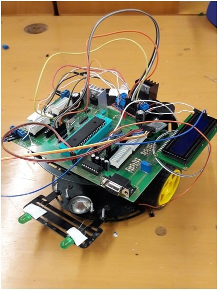
Components of Bluetooth Controlled Robot
Followings are the main components used in Bluetooth controlled robot and all these components are very easy to use. I will explain working of each of this components for used in this Bluetooth Controlled Robot. Lets explain them one by one.
- Pic microcontroller: This is a main part of this project. Pic microcontroller take main actions like receiving data from Bluetooth module and to control the motors based on received data from Bluetooth module. Microcontroller receives data from BT module through serial communication or UART communication. In serial communication data is transferred bit by bit only one bit at time. Motor driver also gets signal from microcontroller.
- Motor Driver L298D: Now the question is why we need to use Motor driver L298D. Because we want to drive motors and microcontroller pins can not provide enough output current to drive motors. Another reason to use this dual full bridge driver is that we want to control direction and speed of both dc motors. It is possible with dual full bridge driver only.
- DC motors: Two dc motors are used which are interfaced with microcontroller through dual full bridge driver. When both motors rotate clock wise, robot will move forward and when both motors will rotate anti-clock wise, robot will move reverse. Similarly when one motor rotates clock wise with increasing speed and one motor rotates anti-clock wise with decreasing speed, Bluetooth Controlled Robot will move either left or right. Movement direction of robot depends on which motor is rotating clock wise and which is rotating anti-clock wise. The mechanism is similar to car control system.
- HC-05 Bluetooth module: HC-05 module is interfacing with pic microcontroller through serial or UART communication. HC-05 gets commands from android app wireless and send data to pic microcontroller receive pin.
- Android application. We have used Bluetooth RC Car Android app. This app connect with HC-05 Bluetooth through mobile app. When both BT modules are paired with each other. User can send commands from this app to HC-05 Bluetooth module. This is a wonderful app.
Circuit diagram of Bluetooth controlled robot
Circuit diagram of bluetooth controlled robot is shown below. I have already explained working and function of each component of this robot above. I assume that you have understand all the things about the circuit diagram. we can also used LCD to show movement of robot.But it is optional. The circuit we used was the micro controller. There was a Bluetooth module attached to the Rx and Tx signal of the kit and the L298 PWM module was attached to the kit:

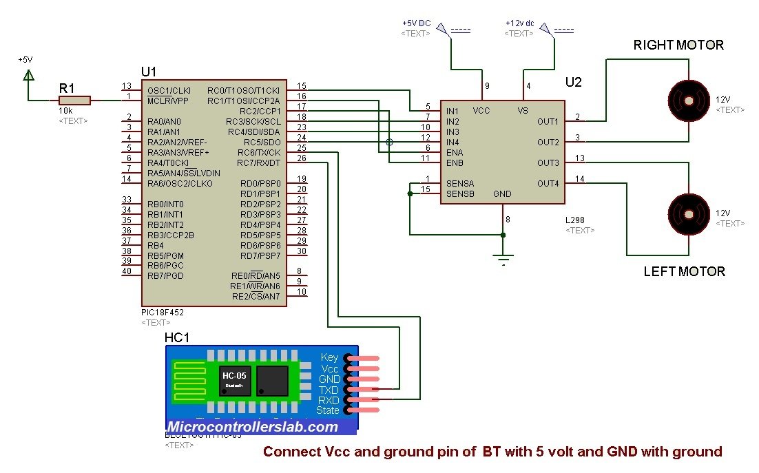
Operating Voltages of all modules are given below:
Bluetooth Module – 3.3V
Microcontroller board – 5V
L298 Motor Driver – 12V
working of Bluetooth controlled robot using pic microcontroller
The user sends a command, either a direction, change of speed, or turning on/off lights/horn, via the Android app interface. The app sends these commands in the form of a single character. HC-05 bluetooth module, received those commands and sends it to the microcontroller. Depending on the command sent, the microcontroller then executes one of the following:
Direction of movement: Microcontroller generates two waves and using PWM, we drive the motors. If the command for forward came, two waves of the same duty cycle are generated and sent to the motors, via L298 motor driver. For Back command, two same waves are sent, but two more inputs that determine the direction of movement are sent to motor driver to then drive the motor. For Forward movements, In1,In3 are set to 1 and In2,In4 are set to 0. For reverse movement, These inputs are reversed, and that reverses the direction of movement of the motor. For moving right, only one wave is sent to the left motor, and right wave is set to zero. For turning left, opposite is done. For moving forward right, forward left, back right, back left, one motor is sent a wave with half the duty cycle of the other, e.g for FR, right motor is half duty cycle in order to move more towards the right.
Change speed: Changing the speed changes the duty cycle of the waves, and thus speed at which motor drives the tyres. Whenever we change speed on app, a single character from 0-10 is sent, and that is then scaled on a scale of 0-255 in order to set duty cycle e.g for speed 1, duty cycle of wave will be 25.
Other commands: In addition to direction and speed, commands to turn on/off front lights, rear light and horn are also implemented. After receiving command form Bluetooth module, microcontroller sends either high or low voltage to the specified output, e.g. high for turning on lights.
Video demonstration of Bluetooth controlled robot using pic microcontroller
so this is all about Bluetooth controlled robot using pic microcontroller. I have explained each and every step and each component you need to design this robot. I believe if you have basic knowledge of programming you can write your own code for this project. If you need code, contact me at microcontrollerslabhub@gmail.com.
Hi Mr. Bilal
My name Hamza and I want to learn about microcontroller and it’s programming techniques from you. My email is hamisbaba@gmail.com.
Expecting your reply.
Thank you.
Hamza
hello sir i will like to know how to set the AT commands for hc05 bluetooth module in mikro c. I have tried but my methods are not working….pls help me.
please send the code and simulation for voice controlled robot car
Hello sir kindly provide me the code of this project
Hi sir
I wanna know how to write program.I make bluetooth controlled robot using pic16f887 ;hc-06 bluetooth module;l298n motor driver and dc motor;android app.plse reply me sir.
plzz can you give me the programming code
Hi sir
I need to do a omnidirectional Bluetooth controlled robot using pic microcontroller and this proyect help me to have idea.
You can provide me the code and the app of the proyect
my mail is edisonyossa@gmail.com
I really appreciation your help.
thanks.
sharing your code pls…for reference
Respected Sir,
Kindly please send the code…