UCC25600 IC is an 8-pin Resonant mode controller having high performance and high efficiency. Boost converters having high voltages and operating under high switching frequency have two serious drawbacks which are core and switching losses. To overcome these losses, converters were designed for controlling the duty cycle and frequency. These converters were easy to implement with other circuit topologies. But, the hard switching at the output leads to poor circuit efficiency. Therefore, we use UCC25600 resonant converter which implements frequency modulation. The output voltage of this controller lies in between – 0.5 V to 22.5 V. It provides low switching losses and high efficiency under low load conditions.
UCC25600 Pinout Diagram

Pin Configuration Description
UCC25600 has total of eight pins.
Pin#01: DT
It is an input pin that sets the dead time of high-side and low-side signals. If deadtime is zero, when both high side and low side MOSFETs turn ON, power rails will be shorted to the ground leading to the burning of FETs and even controller. Therefore, we set a dead time. After one MOSFET switches off, a short dead-time is generated after which another MOSFET switches on. For this purpose, a resistor is connected to this pin. The current flowing through this resistor is used to set the dead time. In case of zero resistance or when the DT pin is shorted to ground, the dead time would set to 120ns.
Pin#02: RT
RT is used to set the frequency of the gate driver signals by connecting the collector of the optocoupler transistor to this pin. It is basically used for regulation purposes. A resistor is used along with an optocoupler transistor to control the switching frequency. If you want to set the minimum switching frequency limit, connect a resistor in parallel with optocoupler otherwise connect a resistor in series for setting maximum switching frequency limit.
Pin#03: OC
Pin 3 is an overcurrent protection pin used to protect the IC against overcurrents. When the voltage at this pin is greater than 2V, the device is latched off. The gate driver signals are set to low logic when the voltage is above 1V at this pin. When this value becomes less than 0.6V, the current value will drop down and the gate driver signals are recovered and set to High.
Pin#04: SS
SS stands for soft-start. This pin is connected through a capacitor to the ground and is used to set the soft-start time of the pin. If the voltage at this pin is below 1 V, the device is disabled. After all fault conditions, this function is enabled again. The switching frequency is increased during this function. It acts as an ON /OFF control pin.
Pin#05, 08: GD1 and GD2
GD1 and GD2 are the outputs of High and low-side switch gates. Connect gate driver transformer primary side to these GD2 two pins to drive the half-bridge.
Pin#06: GND
It is connected to the ground of the circuit.
Pin#07: VCC
VCC is the positive pin of the voltage supply.
UCC25600 Features
- UC25600 is a variable switching frequency regulator having 350kHz switching frequency.
- It has two outputs along with programmable dead-time which maximizes the efficiency of a system.
- A gate driver is integrated inside the chip with 0.4-A Source and 0.8A sink capability.
- The programmable soft-start function is provided to ensure reliability and zero voltage switching.
- Overcurrent protection is provided to protect the system under excessive load current conditions.
- It has a built-in over-temperature protection circuitry which will pull both gate drivers to low logic when the junction temperature rises above 160°C, and restart them with soft-start function when the temperature of junction drops below 140°C.
- The maximum duty cycle is 50 %.
- It has high performance and high efficiency with an output current of 800 mA.
Where to use it?
It is designed especially for dc-to-dc applications. Due to its capability of switching regulation, it is highly efficient than linear circuits. It is used in digital TV, ac-to-dc adapters, and computer power supplies due to its high-power density and soft-switching capability.
UCC25600 Equivalent
- ACT4514 Buck Converter
- CS51411 Buck Regulator
- TS2580
- MCP16252
How to use UCC25600 Resonant Mode Controller?
UCC25600 is an LLC resonant mode highly efficient controller with soft-start function and protection mechanisms against overcurrent, overtemperature and over-voltages integrated inside the IC. It is easy to use and cost-effective due to which it is employed in a wide variety of applications. It has an internal oscillator which is used to switch the frequencies. The switching frequency is proportional to the current flowing through the RT pin. The minimum and maximum frequencies can be limited by controlling this current though connecting resistors at this pin.
Example Circuit
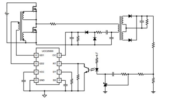
You can see a resistor connected to DT pin. It is used to set dead-time. The output voltages are regulated based on input and output conditions by adjusting the switching frequency. The value of switching frequency is decreased to maintain regulation when the input voltage drops down to low.
Applications
It is used in:
- ATX Power Supplies
- Computer adaptors
- LCD, Plasma, and DLP® TVs
- Home Audio Systems
- Electronic Lighting Ballasts
2D Diagram
UCC25600 is available in SOIC 8-lead package whose 2-dimensional diagram is given below.

Resonant Controller UCC25600 Datasheet