In this tutorial, we will discuss 5V single channel relay modules and their important features such as pinout, pin configuration details, features, working, interfacing with microcontrollers and applications. Relay is an electro-mechnical device which acts as a switch. DC electrical current is used to energize the relay coil which opens or closes the contact switches. Internal circuit of a single channel 5V relay consists of normally open contacts, normally closed contacts and a coil.
5V Single channel Relay Module Pinout
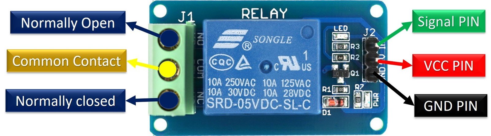
Let’s first discuss the pinout and pin configuration details of the 5V single channel relay module. The following diagram shows its pinout diagram. It is known as a single channel because only one relay is used and it operates on 5V.
Pin details
Relay module consists of six pins such as normally open pin , normally closed, common , signal, Vcc and ground pins.
Signal Pin : It is used to control the relay. This pin can be active low or active high. In case of active low, the relay will activate when we apply an active low signal to the signal pin. On the contrary, in the case of an active high, the relay will activate when we apply an active high signal to the signal pin. But usually, these modules work on an active high signal. This signal will energize the relay coil to make contact with the common terminal with the normally open terminal.
Vcc Pin : As its name suggests, it is a 5V relay. That means it requires 5V DC to operate. Hence, connect the 5v DC power supply to this pin.
Ground Pin : Connect it with the ground terminal of 5V power supply. Furthermore, if you are driving a relay module with a microcontroller, also connect this pin with the ground terminal of the microcontroller.
Common Pin: This terminal is connected with the load that we want to switch with the relay module.
NC Pin : As the name of the normally close terminal suggests, it is normally connected with the COM pin and forms a closed circuit. But this normally closed connection breaks when the relay is activated by applying an active high or active low signal to the signal pin of the relay module from a microcontroller.
NO Pin: This pin is normally open unless we apply an activation signal to the signal pin of the 5V single channel relay module. In this case, the COM pin breaks its connection with the NC pin and makes a connection with the NO pin.
5V Single-Channel Relay Module Components
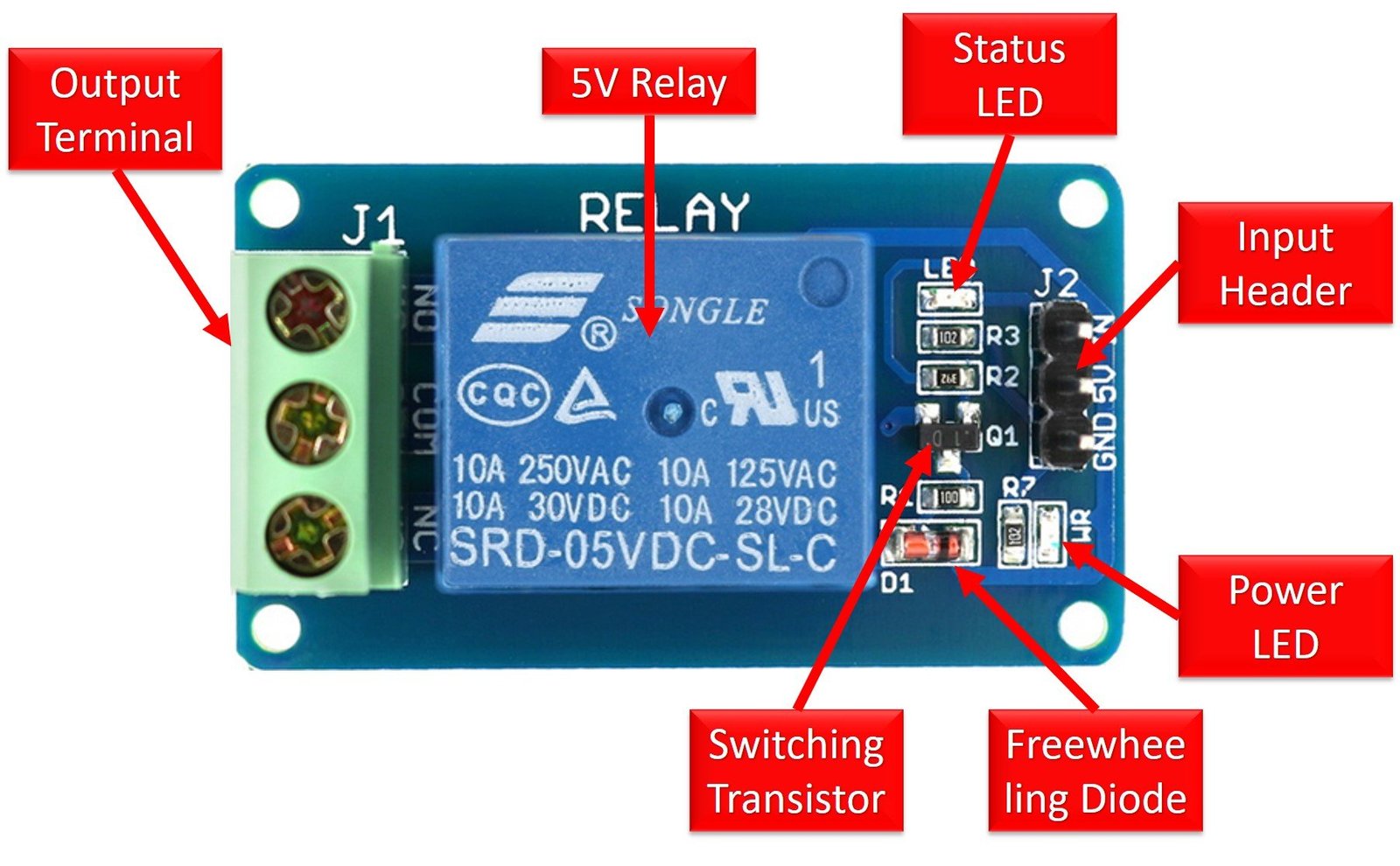
The following figure depicts all the components of a 5V single-channel relay module.
Relay
At the heart of the module is a 5V relay covered in blue color plastic. Maximum operating current and voltage for both AC and DC load are also mentioned at the top of the relay cover. SRD-05VDC-SL-C is part number and it shows the operating voltage. It is known as a 5V relay module. Because the relay operates at 5V DC. In other words, a 5V active high or low signal activates the relay by energizing its coil. As mentioned earlier, internally a 5V relay consists of a NC, NO, COM terminals and a coil.
Output Terminal
On the left hand of this figure is an output terminal which is used to connect a DC/AC load and DC/AC input power source. We will discuss the wiring diagram to connect a LOAD and power source with this terminal in later sections of this tutorial. Each terminal of the output connector is connected with NO, NC and COM pins of 5V relay. Each point of the module has screws which make it easy to connect cables and wires with the relay module. This 5V relay module supports 10A maximum output current and maximum contact voltage of 250V AC and 30V DC. If you are using a high AC voltage and high current load with this module, you should use thick main cables.
Status LED
Status LED is SMD LED which is connected through current limiting resistor and it is available on top right corner of the module. It shows the status of the relay. In other words, the status LED turns on when the relay is active and the coil is energized through a signal input pin. The DC current passes through a relay coil.
Power LED
Power LED is also a SMD type and it shows the status of power source connected with the 5V single channel relay module. Do not connect more than 5V source to Vcc and GND pins of the module. Otherwise, higher voltage may damage the status and power LEDs.
Freewheeling Diode
A freewheeling diode is connected across the coil to avoid the effect of back EMF. It is also known as a flyback diode. The coil used in the relay is an inductive type. When the current passes through an inductive load, it produces an back EMF voltage. This back EMF may damage the circuit. Therefore, a freewheeling diode is used to avoid this effect.
Input Connector
On the right hand side of the relay module is an input connector. It is used to provide input signal and 5V power supply. Furthermore, it also provides power to the status LED, power LED and relay coil.
Switching Transistor
We usually provide an input signal to a relay from the general-purpose input-output pins of microcontrollers such as Arduino, TM4C123, ESP32, etc. But the maximum current sourcing capability of GPIO pins is generally less than 20mA. Hence, a switching transistor is used in this relay module to amplify current to the level of the minimum current requirement of the relay coil. By using a switching transistor, we can control the relay from the GPIO pin of a microcontroller.
Note: Some relay modules also come with an optoisolator as a switching device to provide optical isolation between low and high voltage circuits.
But if you are using a standalone relay without a module and you want to use multiple relays in your projects. You can use a relay driver IC to drive multiple arrays from GPIO pins of a microcontroller. You can read about relay driver ICs here:
- ULN2003
- Relay driver circuit using uln2003
- Microcontroller interfacing to relays using ULN2003
- INTRODUCTION TO ULN2803 – relay driver IC
How to use 5V Single Channel Relay Module?
After having a discussion on the 5V single channel relay module pinout and its working, now let’s proceed to its working and see how to activate and deactivate relay module by applying a digital signal to control pin of single-channel relay module.
The following circuit shows the internal circuit diagram of a 5V single channel relay module.

As you can see in the circuit diagram, the internal circuit of 5V single-channel relay module consists of a transistors, two resistors, two light emitting diodes and one 5V relay.
There are two types of relay modules according to a type of control signal used for relay activation. One comes with a NPN transistor and the other with a PNP transistor. If a NPN Transistor is used, the relay will become active when we apply an active high signal on the control pin. On the other hand, if a PNP transistor is used the relay will become active on an active low signal on the control pin.
Proteus Simulation
Now let’s see its working with proteus simulation software. In this proteus simulation, we have designed a NPN type 5 volt single channel relay module. Now as soon as we apply an active high signal to the control pin of a relay, the coil energizes and the relay becomes active by making connection of the COM pin with a Normally open pin. Similarly, when we apply an active low no signal to the control pin of the relay, the coil de-energize through a freewheeling diode and the relay becomes deactivated.

Similarly for PNP type relay modules, an active low signal, activates the relay and an active high signal deactivates the relay.
Control 5V Single-Channel Relay Module with Microcontroller
To control a 5V single-channel relay module with any microcontroller, we need to use a GPIO pin as a digital output pin. Digital output pin provides an active low and active high signal to control pin of relay module. When the relay switches, we can hear an audible clicking sound coming from the relay module.
You can explore further by reading these topics on relay module use with different microcontrollers:
- ESP32 web server control relay and 220 volt lamp
- Relay Module interfacing with pic16f877a microcontroller
- Relay Module interfacing with arduino
Applications
- Home Automation Projects
- Switching an AC voltage load from low voltage DC current
- Electrical isolation between low and high power sources
- Motors speed control with start-delta converters
- Under and over voltage protection system
Here is a list of our previously published projects which we used single channel, two channel and four channel relay modules:
Datasheet
- Touch Screen Based Home Automation System
- wifi based home automation system over cloud using Arduino
- Ethernet based home automation project using Arduino – IoT
- Bluetooth Based Home Automation project using Arduino
- GSM Based Home Automation project using Arduino
- Voice controlled Home Automation using Arduino
- IR remote controlled home automation system using Arduino
- PC based home automation using Arduino
The 1st picture has a mistypo. At J1 top connection labeled as “Normally Closed” while that should be Normally Open (on the PCB also visible the NO)
Hi Bela,
Thanks for pointing out a mistype in the pinout diagram. We have replaced it with the correct one.
controlling a lamp with a relay module and PIR motion sensor using MC atmega328p
using proteus.Provide code and schematic diagram of proteus
As a novice I’m having trouble digesting all the particulars here.
My project is a second hand r/c truck from a thrift store. My 5 volt relay has 6 pins like the demonstrated relay. I’m wanting to power the truck’s motors with a much higher voltage than the receiver outputs. I’m thinking I need the relay to be the switch to complete 18 volts dc going to the truck’s motors. The ground wire of my 18 volt battery is what i want to switch on/off with the relay. I think i can just leave the signal pin disconnected as I wont be using Arduino?
Which diode is used as freewheeling diode in this module? Is it Zener diode?