In this tutorial, we will show you how to use STM32 Blue Pill UART with DMA to transmit and receive data through direct memory access without requiring to involve CPU. In DMA mode, data can be transferred from UART RX data register to user memory without any CPU processing time. By using DMA with UART, we can optimize for high baud rates and reduce the involvement of the CPU.
We will use STM32 CubeIDE to create a project where we will use UART interrupt feature of Blue Pill to send serial data to our system’s serial COM port. By using a USB-TTL converter we will be able to display it on our terminal.
Recommended Components
The following components are used in this project or are helpful for getting started with STM32 Blue Pill development.
| Component | How it’s used in this project | Buy on Amazon |
|---|---|---|
| STM32F103C8T6 Blue Pill Board | The STM32 board receiving UART data via DMA. | Check Price |
| ST-Link V2 Programmer | SWD programmer/debugger used to flash code onto the Blue Pill. | Check Price |
| USB-TTL / FTDI Converter | Connects the Blue Pill’s UART2 to a serial terminal on your PC. | Check Price |
| Breadboard & Jumper Wires | For wiring the USB-TTL converter and programmer to the Blue Pill. | Check Price |
As an Amazon Associate we earn from qualifying purchases. Prices and availability are accurate as of the date/time indicated and are subject to change.
DMA Introduction
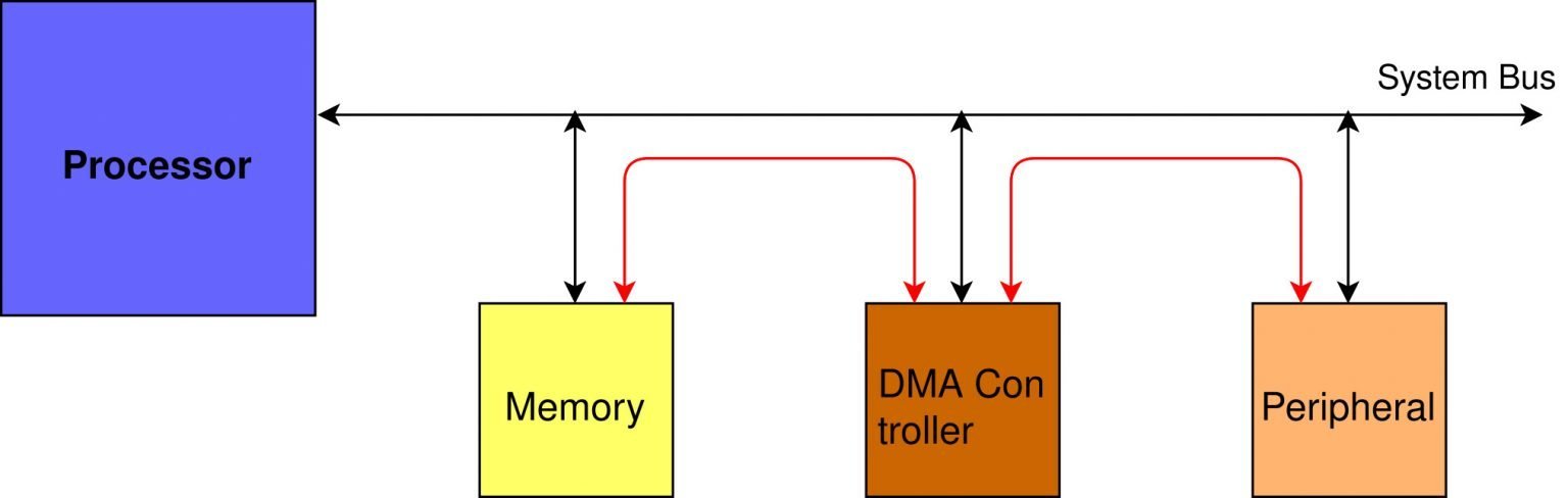
Direct Memory Address typically known as DMA is a data transfer technique in which I/O or peripherals devices such as UART, I2C, SPI, ADC, etc can communicate directly with the memory without passing data through a CPU of STM32 microcontroller. With a DMA controller, we can bypass the CPU unit and data can be transferred between memory and peripherals directly.
A DMA controller is dedicated hardware that performs read and write operations directly without the involvement of the CPU and saves CPU time that involves opcode fetching, decoding, incrementing, and source/destination test addresses that otherwise, central processing units should do. This leads to high data transfer rates between the peripherals and the memory. Additionally, we can transfer large blocks of data at a fast rate.
You can read more about DMA here:
Why use STM32 UART DMA?
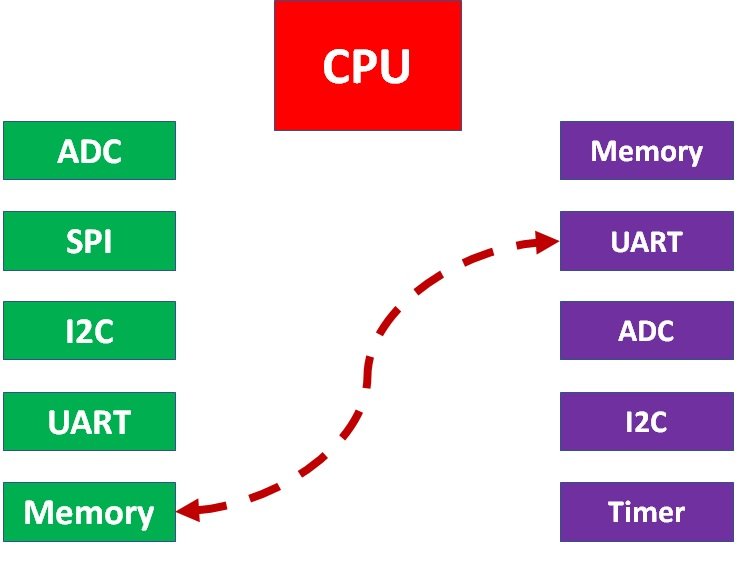
As opposed to polling method where data reception occurs in blocking mode, in UART DMA mode just like UART Interrupt it occurs in the background with non-blocking mode. It is similar to UART Interrupt mode but the difference is that UART DMA does not require CPU involvement. In other words, it keeps the CPU free and can be used for other operations.
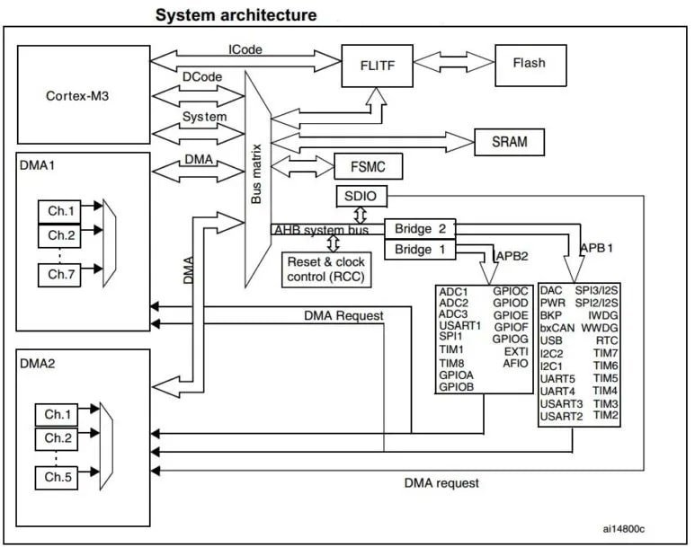
STM32 Blue pill has 2 DMA controllers (DMA1 and DMA2). DMA1has 7 channels and DMA2 has 5 channels. Furthermore, each channel has dedicated resources for managing memory access requests from one or more peripherals which means it has a total of 12 channels which can be used with different peripherals to directly transfer between memory and peripherals.
We can also use each DMA channel with one or more peripherals to handle memory transfer requests. To do so, it provides an arbiter which sets the priority for DMA requests.
STM32 UART DMA Data Transfer Example
In this tutorial, we will perform data transfer from UART to memory. We will send data to the UART2 RX pin of Blue Pill and UART2 peripheral will receive this data and transfer it directly to memory without any CPU action. After that, we will read that data from the buffer and transmit it to the serial terminal for display.
Let us create and build a project in CubeIDE to learn more!
In a previous tutorial, we looked upon Blue Pill UART Communication and how to send and receive data using the polling and interrupt methods:
- STM32 Blue Pill UART Communication Tutorial with CubeIDE and HAL Libraries
- STM32 Blue Pill UART Interrupt with CubeIDE and HAL Libraries
STM32 Blue Pill UART Ports
Blue Pill STM32 consists of three UART modules: UART1, UART2, and UART3.
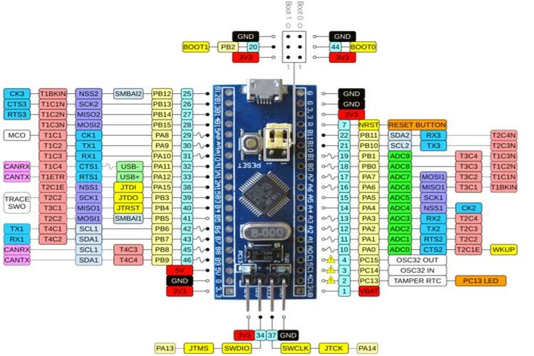
We can use any UART module for serial data transmission. However, you may have noticed that Blue Pill STM32 microcontroller does not have an onboard ST-Link debugger therefore we will need a USB-TTL converter.
One important thing to keep in mind is that pins for UART1 and UART3 are 5V tolerant however pins for UART2 are standard 3.3V pins.
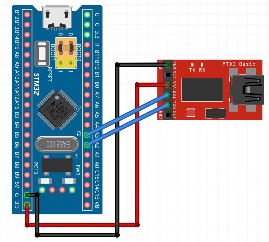
Connect FTDI USB to Serial with STM32 Blue Pill
Let us show you how to connect the FTDI programmer with Blue pill STM32.
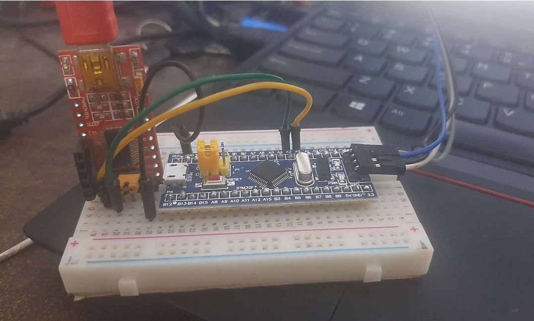
For this guide, we will use the UART2 module pins. VCC of the programmer is connected with 3.3V from the Blue pill and both the GND of the devices are connected together. PA2 is the TX2 pin of STM32 and PA3 is the RX2 pin of STM32. Connect the RX pin of STM32 with TX pin of FTDI and TX pin of STM32 with RX pin of FTDI converter.
STM32 Blue Pill UART DMA Example
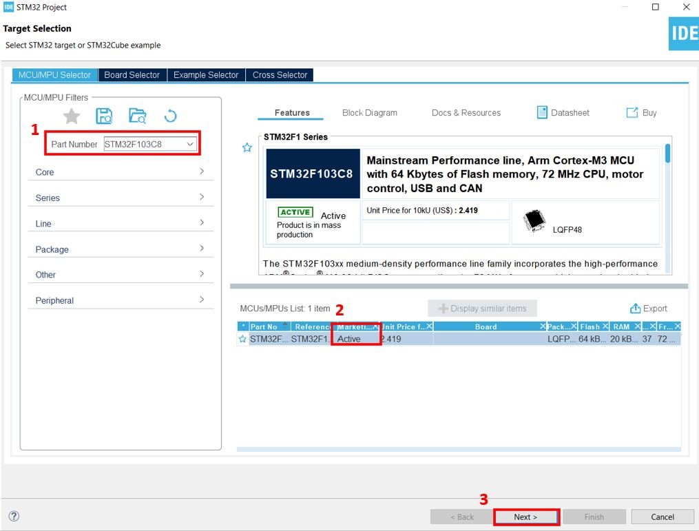
We will use STM32Cube IDE to program our STM32 board. Open the IDE and head over to a new project.
Then for the target selection, specify the STM32 Blue Pill board number. After that click on any column as shown in the picture below. Then click the ‘Next’ button.
Specify the name of your project then click ‘Finish’ to complete the setup of your project.
Now head over to Connectivity > USART2 and set the mode as ‘Asynchronous.’ You can also view the parameter settings of the UART including the baud rate, word length, parity, etc.

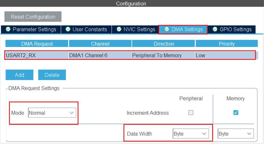
To enable DMA, head over to DMA Settings and add the DMA. As we want to receive data, hence we added the DMA request ‘USART2_RX.’ Here the data width is set as Byte. You have the option to select from byte, half word and word. Characters take one byte of memory hence we set the data width as ‘Byte’ as we will be receiving characters. We have set the mode as ‘Normal.’ You can even set it as ‘Circular’ in which case the DMA continuously receives the data.
Now go to System Core > RCC then select ‘Crystal/Ceramic Resonator’ in from the High Speed Clock feature.

Now we have enabled the RCC external clock source.
Clock Configuration
Next go to the Clock Configuration found at the top. This will open the following window. Here we will select the clock frequency.
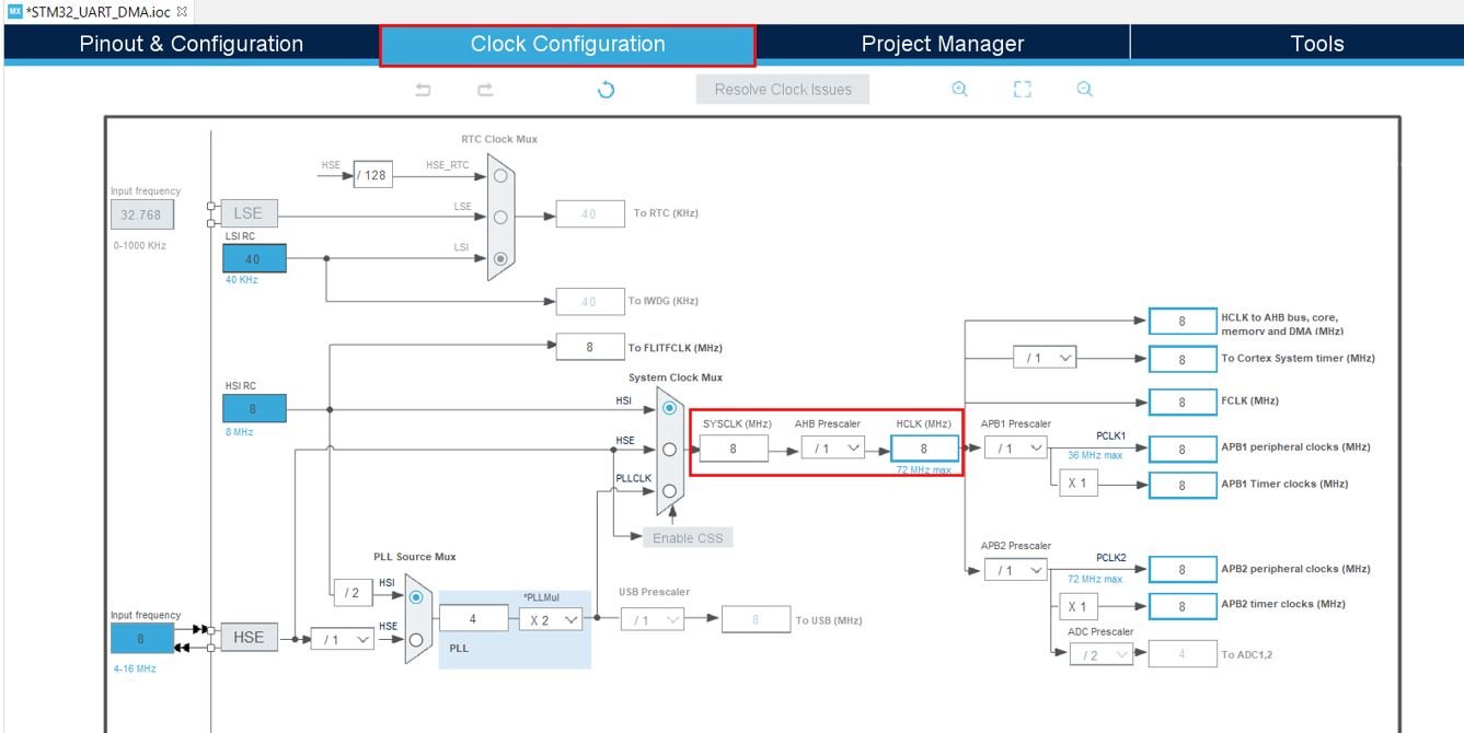
You can specify your system clock. We will set it as 72 MHz. These are the configurations we have set:

Now we will save our file. Press Ctrl + S. The following window will appear. Click ‘Yes.’ This will generate a template code for you.

Another window will appear that will ask if you want to open the perspective. Click ‘Yes.’

STM32 Blue Pill UART DMA Code
Now the following page opens. On the right side, you will be able to view the Outline of the code. This happened because we opened our code with perspective. In the center, you can view the main.c file. If you want to go to the Device Configuration Tool, then click the .ioc tab.
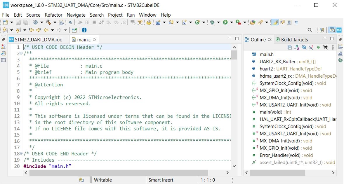
Now let us look at our main.c file that was generated.
Modifying Code
We will set up a code in which STM32 Blue Pill will echo back the received bytes to the sender using UART RX interrupt. The code will echo back whatever it will receive on the Rx pin to the terminal. In other words, whatever you type on the serial terminal, it will be sent to the STM32 Blue Pill and STM32 will transmit it back to the computer.
Inside the main.c file, look for the int main() function. Copy the code given below in the main() function.
int main(void)
{

  HAL_Init();

  SystemClock_Config();

  MX_GPIO_Init();
  MX_DMA_Init();
  MX_USART2_UART_Init();

  HAL_UART_Receive_DMA(&huart2, UART2_RX_Buffer, 26);

  while (1)
  {

  }
}
Also create a receiving buffer of 26 bytes called UART2_RX_Buffer outside the main() function. This will hold the data in the receiving buffer.
uint8_t UART2_RX_Buffer[26] = {0};The HAL_UART_RxCpltCallback() function is called when data reception is completed. This function is known as Rx Transfer completed callback. It takes in a single parameter ‘huart’ which is the pointer to the UART_HandleTypeDef structure containing the configuration parameter for the specified UART module. Inside this function, new data transmission and reception is initiated so that the continuity of the transmission/reception of data remains. This will ensure the data transfer occurs in a non-blocking mode.
void HAL_UART_RxCpltCallback(UART_HandleTypeDef *huart)
{
    HAL_UART_Transmit(&huart2, UART2_RX_Buffer, 26, 100);
    HAL_UART_Receive_DMA(&huart2, UART2_RX_Buffer, 26);
}
HAL UART Data Receive DMA Function
HAL_UART_Receive_DMA() function is responsible for receiving an amount of data in non-blocking mode.
HAL_StatusTypeDef HAL_UART_Receive_DMA(UART_HandleTypeDef * huart,
 uint8_t * pData,
 uint16_t Size)
This function takes in three parameters.
- The first parameter is the pointer to the UART_HandleTypeDef structure containing the configuration parameters for the specified UART module.
- The second parameter is the pointer to the data buffer which holds the received data.
- The third parameter is the size of data to be received.
main.c file
This is how a complete main.c file will be after modification.
#include "main.h"
uint8_t UART2_RX_Buffer[26] = {0};

UART_HandleTypeDef huart2;
DMA_HandleTypeDef hdma_usart2_rx;

void SystemClock_Config(void);
static void MX_GPIO_Init(void);
static void MX_DMA_Init(void);
static void MX_USART2_UART_Init(void);

int main(void)
{

  HAL_Init();

  SystemClock_Config();

  MX_GPIO_Init();
  MX_DMA_Init();
  MX_USART2_UART_Init();

  HAL_UART_Receive_DMA(&huart2, UART2_RX_Buffer, 26);

  while (1)
  {

  }
}

void HAL_UART_RxCpltCallback(UART_HandleTypeDef *huart)
{
    HAL_UART_Transmit(&huart2, UART2_RX_Buffer, 26, 100);
    HAL_UART_Receive_DMA(&huart2, UART2_RX_Buffer, 26);
}

void SystemClock_Config(void)
{
  RCC_OscInitTypeDef RCC_OscInitStruct = {0};
  RCC_ClkInitTypeDef RCC_ClkInitStruct = {0};

  /** Initializes the RCC Oscillators according to the specified parameters
  * in the RCC_OscInitTypeDef structure.
  */
  RCC_OscInitStruct.OscillatorType = RCC_OSCILLATORTYPE_HSI;
  RCC_OscInitStruct.HSIState = RCC_HSI_ON;
  RCC_OscInitStruct.HSICalibrationValue = RCC_HSICALIBRATION_DEFAULT;
  RCC_OscInitStruct.PLL.PLLState = RCC_PLL_NONE;
  if (HAL_RCC_OscConfig(&RCC_OscInitStruct) != HAL_OK)
  {
    Error_Handler();
  }
  /** Initializes the CPU, AHB and APB buses clocks
  */
  RCC_ClkInitStruct.ClockType = RCC_CLOCKTYPE_HCLK|RCC_CLOCKTYPE_SYSCLK
                              |RCC_CLOCKTYPE_PCLK1|RCC_CLOCKTYPE_PCLK2;
  RCC_ClkInitStruct.SYSCLKSource = RCC_SYSCLKSOURCE_HSI;
  RCC_ClkInitStruct.AHBCLKDivider = RCC_SYSCLK_DIV1;
  RCC_ClkInitStruct.APB1CLKDivider = RCC_HCLK_DIV1;
  RCC_ClkInitStruct.APB2CLKDivider = RCC_HCLK_DIV1;

  if (HAL_RCC_ClockConfig(&RCC_ClkInitStruct, FLASH_LATENCY_0) != HAL_OK)
  {
    Error_Handler();
  }
}

/**
  * @brief USART2 Initialization Function
  * @param None
  * @retval None
  */
static void MX_USART2_UART_Init(void)
{

  /* USER CODE BEGIN USART2_Init 0 */

  /* USER CODE END USART2_Init 0 */

  /* USER CODE BEGIN USART2_Init 1 */

  /* USER CODE END USART2_Init 1 */
  huart2.Instance = USART2;
  huart2.Init.BaudRate = 115200;
  huart2.Init.WordLength = UART_WORDLENGTH_8B;
  huart2.Init.StopBits = UART_STOPBITS_1;
  huart2.Init.Parity = UART_PARITY_NONE;
  huart2.Init.Mode = UART_MODE_TX_RX;
  huart2.Init.HwFlowCtl = UART_HWCONTROL_NONE;
  huart2.Init.OverSampling = UART_OVERSAMPLING_16;
  if (HAL_UART_Init(&huart2) != HAL_OK)
  {
    Error_Handler();
  }
  /* USER CODE BEGIN USART2_Init 2 */

  /* USER CODE END USART2_Init 2 */

}

/**
  * Enable DMA controller clock
  */
static void MX_DMA_Init(void)
{

  /* DMA controller clock enable */
  __HAL_RCC_DMA1_CLK_ENABLE();

  /* DMA interrupt init */
  /* DMA1_Channel6_IRQn interrupt configuration */
  HAL_NVIC_SetPriority(DMA1_Channel6_IRQn, 0, 0);
  HAL_NVIC_EnableIRQ(DMA1_Channel6_IRQn);

}

/**
  * @brief GPIO Initialization Function
  * @param None
  * @retval None
  */
static void MX_GPIO_Init(void)
{

  /* GPIO Ports Clock Enable */
  __HAL_RCC_GPIOA_CLK_ENABLE();

}

/* USER CODE BEGIN 4 */

/* USER CODE END 4 */

/**
  * @brief  This function is executed in case of error occurrence.
  * @retval None
  */
void Error_Handler(void)
{
  /* USER CODE BEGIN Error_Handler_Debug */
  /* User can add his own implementation to report the HAL error return state */
  __disable_irq();
  while (1)
  {
  }
  /* USER CODE END Error_Handler_Debug */
}

#ifdef  USE_FULL_ASSERT
/**
  * @brief  Reports the name of the source file and the source line number
  *         where the assert_param error has occurred.
  * @param  file: pointer to the source file name
  * @param  line: assert_param error line source number
  * @retval None
  */
void assert_failed(uint8_t *file, uint32_t line)
{
  /* USER CODE BEGIN 6 */
  /* User can add his own implementation to report the file name and line number,
     ex: printf("Wrong parameters value: file %s on line %d\r\n", file, line) */
  /* USER CODE END 6 */
}
#endif /* USE_FULL_ASSERT */
Save the main.c file after modifying it. Now we are ready to build our project.
Building the Project
To build our project press Ctrl + B or go to Project > Build All.
Your project will start building. After a few moments, your project will be successfully built if there are no errors.
Connecting ST-Link Programmer with STM32
Now as we have successfully built our project let us move ahead and upload the code to our STM32 board. To do that, first we will have to connect our Blue Pill STM32 with a ST-Link programmer. We will be using ST-Link V2.

This will provide an interface between our computer and our STM32 board. It consists of 10 pins. We will be using pin2 SWDIO, pin6 SWCLK, pin4 GND, and pin8 3.3V to connect with our STM32 board. The SWDIO is the data input/output pin and the SWCLK is the clock pin. Follow the pin configuration given on the ST-LINK V2 to identify each pin.
Follow the table below to connect both devices correctly.
| STM32 | ST-LINK V2 |
| VCC 3.3V pin | pin8 3.3V |
| SWDIO pin | pin2 SWDIO |
| SWCLK pin | pin6 SWCLK |
| GND pin | pin4 GND |

Additionally move the BOOT jumper to the right to enable the microcontroller to go into programming mode.

Now connect your ST-LINK V2 with your computer via the USB port. Both the devices will power ON.
Next press the RUN button in the IDE. The ‘Edit configuration’ window will open up. Click ‘OK’.
After a few moments, the code will be successfully sent to the STM32 board.
Otherwise, press the RESET button on your STM32 board.
Now to bring the Blue pill back to normal mode make sure you bring the BOOT jumper back at its place.
Now connect the USB to TTL serial converter with the STM32 board as mentioned previously. Open Device Manager and head over to Ports to check the COM port through which the USB-TTL converter is connected. It is COM5 in our case.

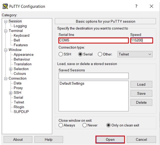
Open a terminal on your system for example Putty. Set the correct speed and COM port and then press Open to establish a connection.
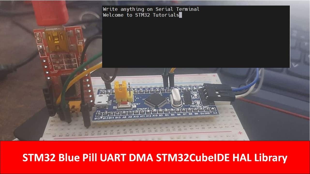
Press the Reset button of STM32. Now type any characters and they will get displayed in the terminal. If you types 26 characters on serial monitor as soon as you complete writing 26 characters they will display on putty terminal as shown below:
You may also like to read:
Very good explanation , can you please explain how to perform simple addition program using this UART by taking input through console and giving output to the console