In this tutorial, we will discuss how to use GPIO interrupts which are also known as external interrupts of STM32 Nucleo. We will learn to configure GPIO interrupts as edge-triggered such as positive or negative edge or level triggered such as active high or active low level triggered.
GPIO Interrupts Introduction
General-purpose input-output pins are vital components of embedded systems. GPIO pins allow easy integration of external components with microcontrollers. Input pins allow microcontrollers to receive information from the external world and output pins are used to display information or control devices such as motors, etc.
Interrupts Introduction
Interrupts are used to handle events that do not happen during the sequential execution of a program. For example, we want to perform certain tasks and these tasks execute sequentially in your program. But there are few tasks that only execute when a special event occurs such as an external trigger signal to the digital input pin of a microcontroller.
An external interrupt or a ‘hardware interrupt’ is caused by the external hardware module. For example, there is a Touch Interrupt which happens when touch is detected, and a GPIO interrupt when a key is pressed down. In this tutorial, we will focus on this type of interrupt.
How ISR Routine Work?
With interrupt, we do not need to continuously check the state of the digital input pin. When an interrupt occurs (a change is detected), the processor stops the execution of the main program, and a function is called upon known as ISR or the Interrupt Service Routine. The processor then temporarily works on a different task (ISR) and then gets back to the main program after the handling routine has ended.
This is shown in the figure below.
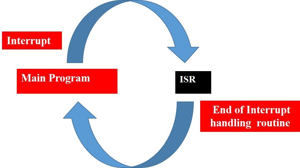
An example can be that of pressing a push button or motion detection with a PIR Sensor. In both cases, a push button or a PIR motion sensor can be used to trigger an interrupt. Therefore, when an external event occurs, the processor stops what it is doing and executes the interrupt service routine which we define for the respective event. After that, it returns to the current program. External Interrupts are extremely useful because with their help we do not have to constantly monitor the digital input pin state.
Why do we need to use GPIO Interrupts?
In the last tutorial on controlling an LED with a push button using STM32 Nucelo, we have seen an example to control an onboard LED of STM32 Nucleo using an onboard push button (PC13). In that tutorial, the STM32 microcontroller keeps checking the state of the push button by polling the PC13 pin. But one of the main drawbacks of the polling method is that microcontroller will have to check the status of input switches on every sequential execution of the code or keep monitoring continuously (Polling method). Therefore, external or GPIO interrupts are used to synchronize external physical devices with microcontrollers.
Hence, instead of checking the status of input switches continuously, a GPIO pin which is configured as digital input can be initialized to produce an interrupt whenever the state of the switch changes. A source of interrupt trigger can be on falling edges, rising edges, or both falling and rising edges, level triggered also.
In summary, the use of external GPIO interrupts makes the embedded system event-driven and responsive. They make use of the microcontroller’s processing time and computing resources efficiently.
You can learn more about interrupt processing in ARM Cortex-M microcontrollers in the following article:
STM32 Interrupts Controller
STM32 microcontrollers are ARM Cortex-M series-based Microcontrollers. In ARM Cortex-M microcontrollers, a nested vectored interrupt controller usually known as NVIC is used to handle all the interrupts and exceptions that Cortex-M supports.

The nested vectored interrupt controller is basically an integrated part of ARM Cortex-M because of its tight integration with the cortex-M core. We can also configure the interrupt controller according to our needs using specific registers. The mode of operation of most of the interrupt registers is privileged i.e. they can only be accessed in privileged mode, but if the interrupt is a software interrupt then these registers can be accessed in user mode also. The followings are the main responsibilities of NVIC:
- Interrupts handling
- Programmable interrupt feature
- Interrupt tail chaining
- Low interrupt latency management
Let us learn about the important features which are needed to configure external interrupts in STM32 microcontrollers
Interrupt Lines (EXTI0-EXTI15)
The STM32 microcontrollers provide different numbers of external interrupt sources and external interrupt controller lines. The number may vary depending on which STM32 family microcontroller you are using such as STM32F1, STM32F4, STM32F7, etc.
GPIO pins connect with the nested vector interrupt controller through EXTI lines as shown below. For example, the first section corresponds to external pins on each port which are P0-P15. The second section corresponds to RTC, ethernet, and USB interrupts. Therefore, in the first section, we have 16 lines corresponding to line 0 to line 15. All of these map to a pin number.
The diagram below shows how the GPIO pins are connected to the 16 interrupt lines:
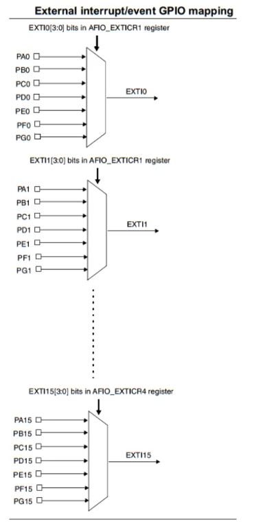
One important thing to note here is that the multiple input pins are connected with a single external interrupt controller line. Hence, only when the interrupt source or input line can be used with a specific EXTI line. For example, out of PA1, PB1, PC1, PD1, PE1, PF1, and PG1, you can only use a single pin out of all these with an EXTI1 line. This is because they are all connected to the same line EXTI1. However, you can use PA1 and PA2 at the same time as they are connected with different lines.
Now each of these lines EXTI0-EXTI15 can be used to trigger an interrupt on different modes of the signal: rising edge, falling edge, or rising_falling edge.
Interrupt Handler (ISR)
The next important feature is the ISR or the interrupt handler. In order to handle the interrupts we use the ISR function.
The table below shows the different interrupt handlers for the GPIO pins:
| GPIO Pin | IRQ | Handler | Description |
| 0 | EXTI0_IRQn | void EXTI0_IRQHandler() | Handler for pins connected to line 0 |
| 1 | EXTI1_IRQn | void EXTI1_IRQHandler() | Handler for pins connected to line 1 |
| 2 | EXTI2_IRQn | void EXTI2_IRQHandler() | Handler for pins connected to line 2 |
| 3 | EXTI3_IRQn | void EXTI3_IRQHandler() | Handler for pins connected to line 3 |
| 4 | EXTI4_IRQn | void EXTI4_IRQHandler() | Handler for pins connected to line 4 |
| 5 | EXTI9_5_IRQn | void EXTI9_5_IRQHandler() | Handler for pins connected to line 5 |
| 6 | EXTI9_5_IRQn | void EXTI9_5_IRQHandler() | Handler for pins connected to line 6 |
| 7 | EXTI9_5_IRQn | void EXTI9_5_IRQHandler() | Handler for pins connected to line 7 |
| 8 | EXTI9_5_IRQn | void EXTI9_5_IRQHandler() | Handler for pins connected to line 8 |
| 9 | EXTI9_5_IRQn | void EXTI9_5_IRQHandler() | Handler for pins connected to line 9 |
| 10 | EXTI15_10_IRQn | void EXTI15_10_IRQHandler() | Handler for pins connected to line 10 |
| 11 | EXTI15_10_IRQn | void EXTI15_10_IRQHandler() | Handler for pins connected to line 11 |
| 12 | EXTI15_10_IRQn | void EXTI15_10_IRQHandler() | Handler for pins connected to line 12 |
| 13 | EXTI15_10_IRQn | void EXTI15_10_IRQHandler() | Handler for pins connected to line 13 |
| 14 | EXTI15_10_IRQn | void EXTI15_10_IRQHandler() | Handler for pins connected to line 14 |
| 15 | EXTI15_10_IRQn | void EXTI15_10_IRQHandler() | Handler for pins connected to line 15 |
We have a total of seven interrupt handlers according to the pin which we will set up as the external interrupt pin. This is because Line 5-Line 9 and Line 10-Line 15 have the same interrupt handler.
The IRQ has to be set for NVIC and the handler shows the prototype of the handler function.
To use this button, we should configure the PA0 pin of GPIOA as a digital input pin.
External Interrupt with Push Button STM32 Nucleo
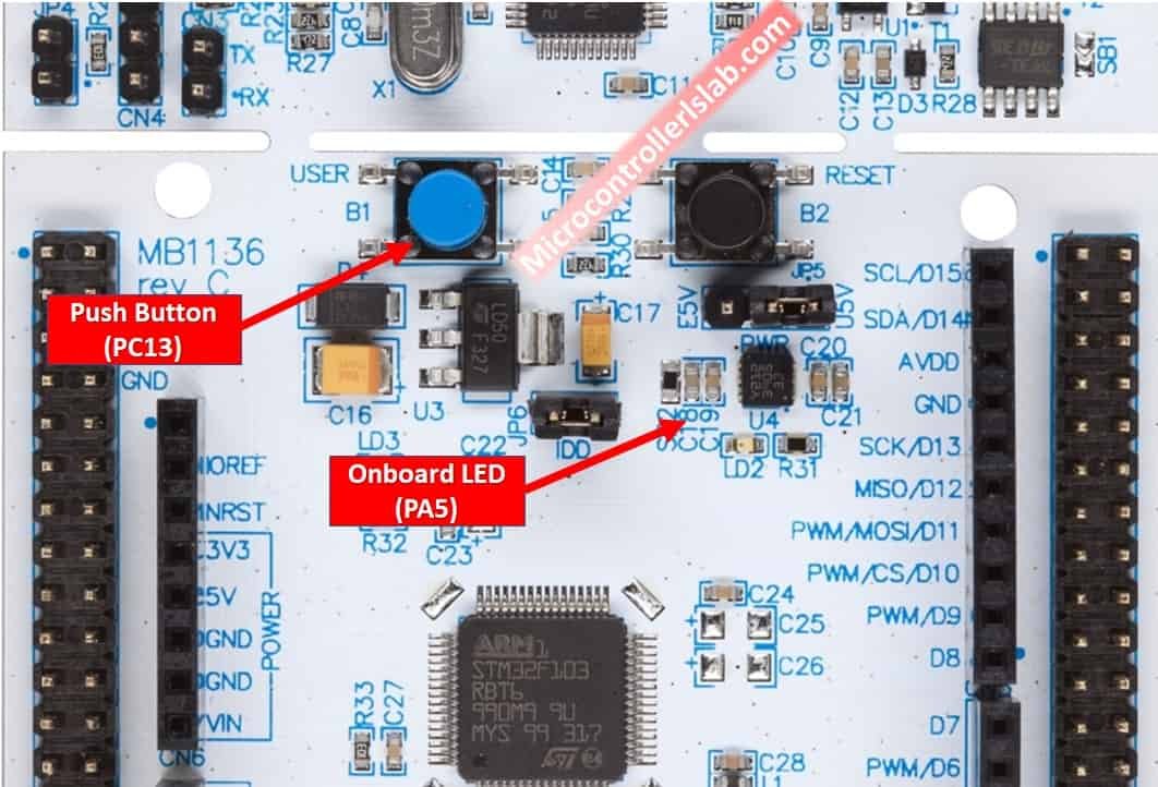
For demonstration purposes, we will control the onboard LED of STM32 Nucleo board with a push button and instead of a polling method, we will use an interrupt method to capture state whenever the state of input changes.
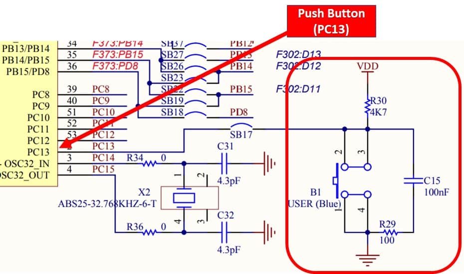
We will use the onboard push button of STM32 Nucleo. As you can see in the following schematic diagram, the onboard user push button is connected to PC13 digital pin through a pull-up resistor. This means when the push button is not pressed, we will get an active high signal at the PC13 pin. Similarly, when it is pressed, we will get an active low signal on the PC13 pin.
In the last tutorial, we learned to control onboard LED, If you don’t know how to configure GPIO pins as digital output pins, you should read that tutorial from this link:
As discussed earlier, we can configure GPIO interrupts of STM32 to detect the rising or falling edges of a signal. The onboard push button of STM32 Nucleo is connected to an external pull-up resistor. Hence, in default condition, the state of the input pin remains active high. However, when we press the push button, the input pin detects a falling edge. Likewise, when we release the push button, the input pin detects a rising edge.

In this tutorial, we will configure PC13 pin of STM32 as an external interrupt source pin with falling edge detection mode. Whenever PC13 pin detects a falling edge, we will toggle the onboard LED of STM32 Nucleo.
Create STM32 Nucleo External Interrupts STM32CubeIDE Project
After installing STM32CubeIDE on your Windows, Linux, or MacOS system, follow these steps to create a project. In this section, you will learn the followings:
- create and configure the STM32CubeMX project and generate the initialization code
- program and use HAL functions to define interrupt service routine to read the push button state and control the LED on the NUCLEO-F103RB board.
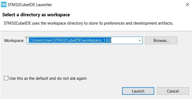
Launch STM32CubeIDE: Open the STM32CubeIDE application on your computer. You will be asked to specify the directory for the workplace. You can specify the directory and also tick the box below to keep this as the default directory. Next, click ‘Launch’ to start the application.
The STM32Cube workspace will open. Now click ‘Start new STM32 project’.

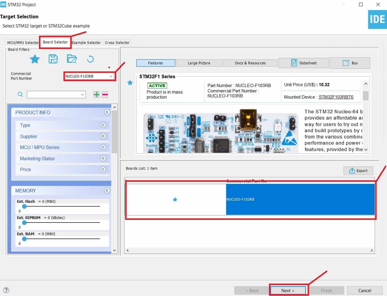
From Board Selector section, type STM32 Nucleo-F103RB and select it. Click next.
Give your project a name. As we are going to blink the on-board LED of STM32 Nucleo-F103RB hence we have named our project ‘BLINK_LED.’ Then click ‘Finish.’

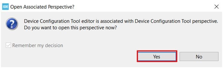
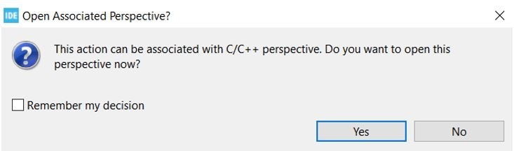
You will be asked to open an associated perspective to start generating code with STM32CubeMX. Click ‘Yes’.
STM32 Nucleo GPIO Pins Configiuration
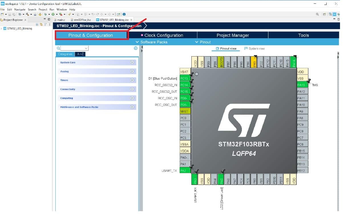
Now the Device Configuration Tool window will open up. In the pinout and configuration window, we can select a specific pin and its function. A single GPIO pin may have multiple alternate functions. For example, the same GPIO pin can be used for ADC, SPI, UART peripherals, etc. But only one function can be used at a time.
As mentioned earlier, we will use an onboard LED of STM32 Nucleo-F103RB board. The onboard LED of Nucleo-F103RB board is connected with a PA5 pin. When you create a project for Nucleo-F103RB, you will see that it has already been configured for the PA5 pin. But you can change it according to your requirement.
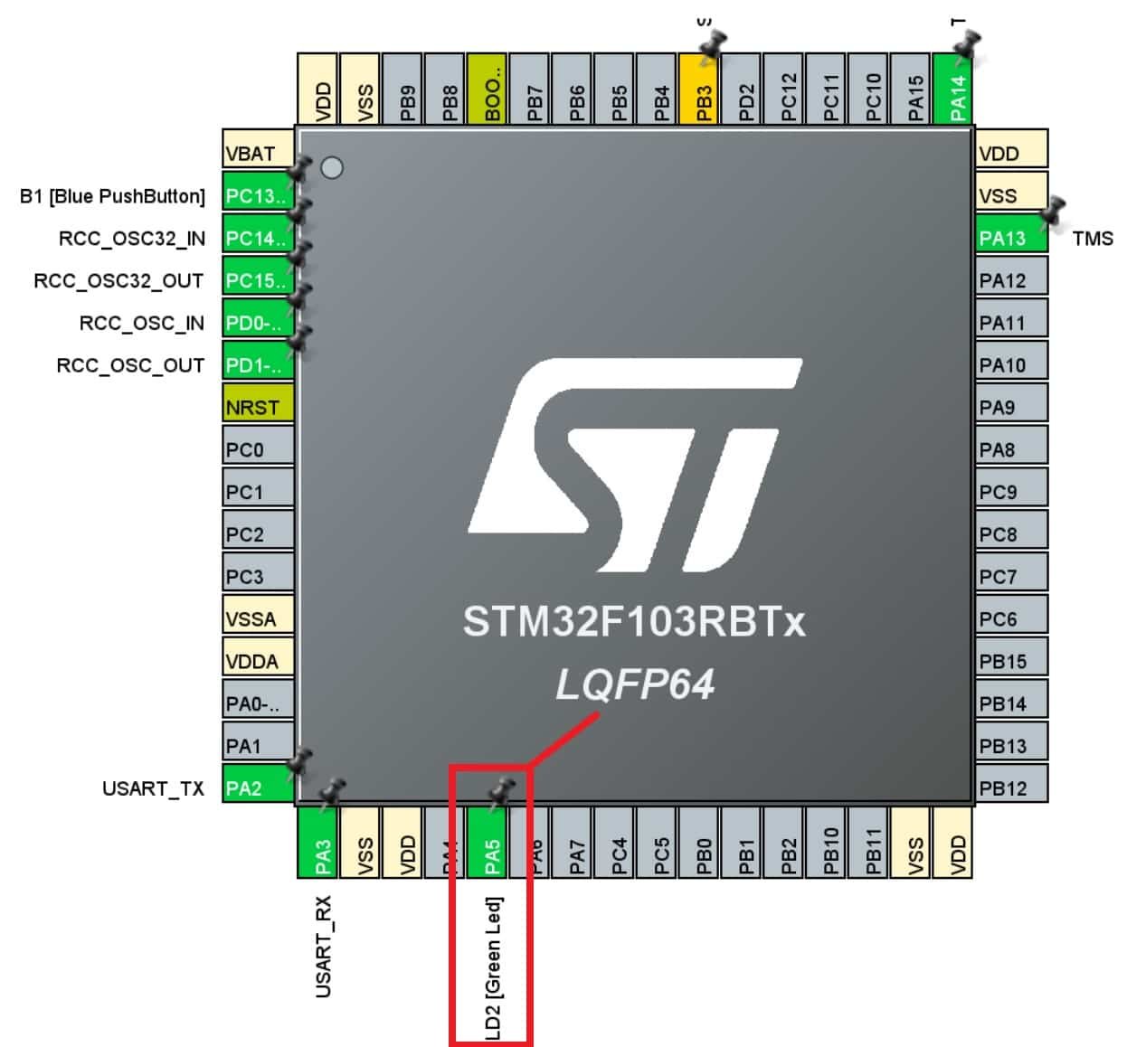
Click on the PA5 pin, and a list of all alternate functions will appear associated with the PA5 pin. We will set this pin as a ‘GPIO Output.’
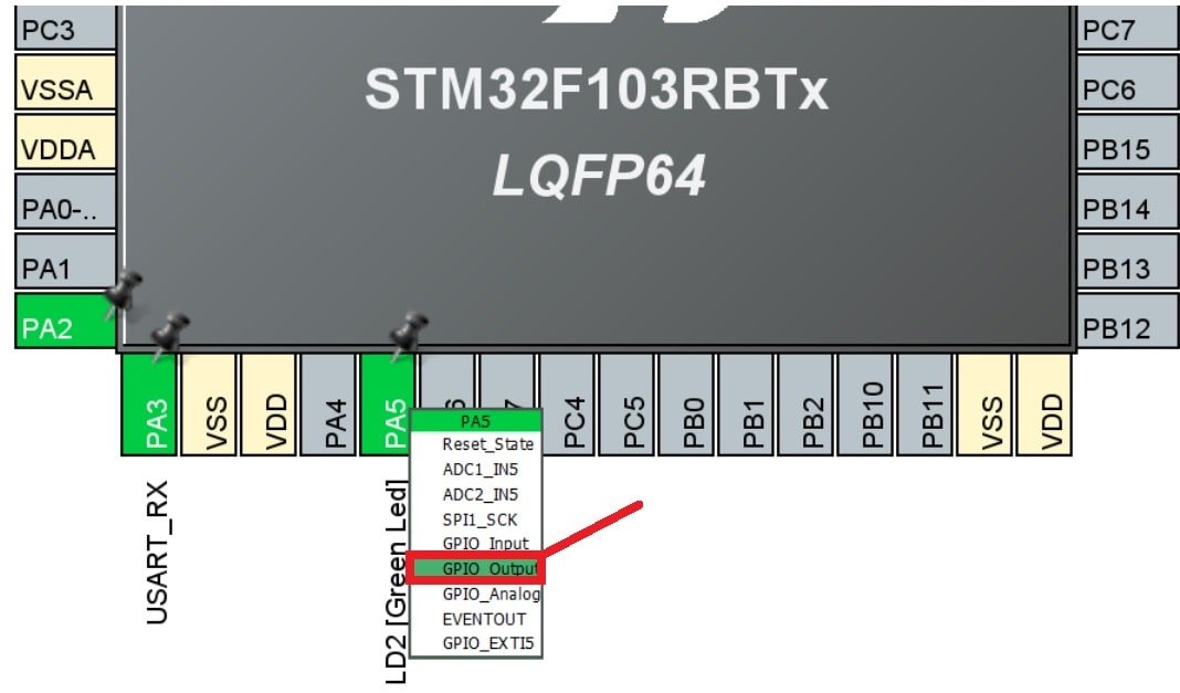
This is how it will look. Here you can see that we have attached GPIO_Output to PA5.
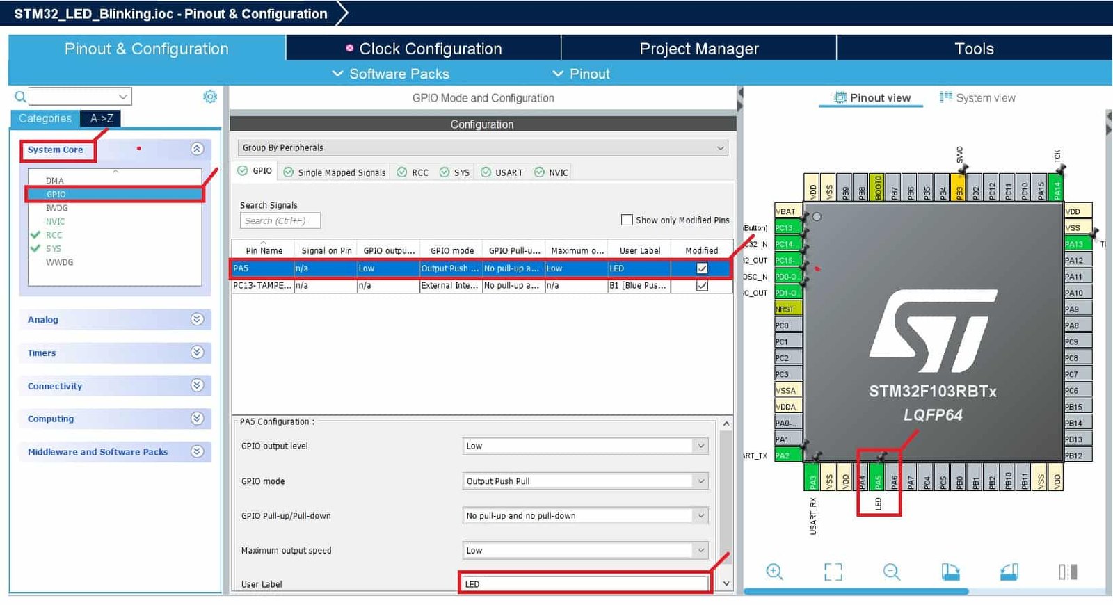
Additionally, we have more options for pins as well. Go to System Core > GPIO > PA5 and the pin configuration for PA5 will open up. Here we have given the pin a user label of ‘LED.’ You can see in Device Configuration Tool, that now PA5 has been given the label ‘LED.’
Apart from the label, there are several other options to choose from including GPIO output level, mode, pull-up/pull-down state, etc.
In the GPIO Tab, select Pin Name column PA5 to display the corresponding GPIO parameters and configuration to drive the Nucleo-F103RB LED:
- GPIO Output level: By default, the output level is set to Low, meaning the pin is at a low voltage. However, you can change it to High if needed.
- GPIO mode: The mode automatically configures the pins with the appropriate alternate function and sets them to Output Push Pull mode, ensuring compatibility and stability.
- GPIO Pull-up/Pull-down: By default, no pull-up or pull-down resistors are enabled. However, depending on your requirements, you can configure pull-up or pull-down options if supported by the specific pin.
- GPIO Maximum output speed: The maximum output speed is initially set to Low for power consumption optimization. However, if your application requires a higher frequency, you can change this setting accordingly.
- User Label: This is a customizable name assigned to a GPIO pin for easier identification and access. You can assign a meaningful label, and later use the Find menu to locate and work with the GPIO pin based on its label.
These configurations and parameters allow you to customize the behavior of the GPIO pins to suit the needs of your specific project and ensure proper functionality.
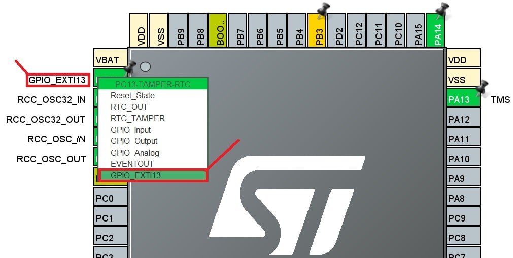
Now select the PC13 pin as an external interrupt source by selecting option GPIO_EXTI13 as shown below. PC13 pin is connected with external interrupt controller line 13.
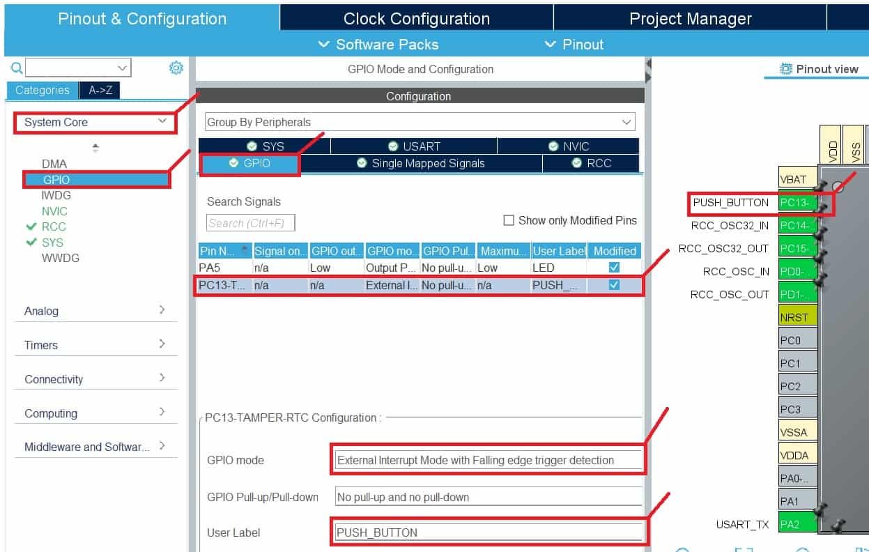
Also, go to System Core > GPIO > PC13 and the pin configuration for PC13 will open up. Here, give the label to the PC13 pin by giving it whatever name you want. You will see in Device Configuration Tool, that now PC13 will be labeled accordingly.
From GPIO mode, select “External Interrupt Mode with Falling edge trigger detection”. Similarly, you can also select a falling edge or both rising/falling together from the options. But in this example, we are using falling edge detection mode.
Furthermore, as you can see we have not selected a Pull-up or pull-down resistor from GPIO Pull-up/Pull-down option. Because the onboard push button of STM32 Nucelo already has an external pull-up resistor connected to it.
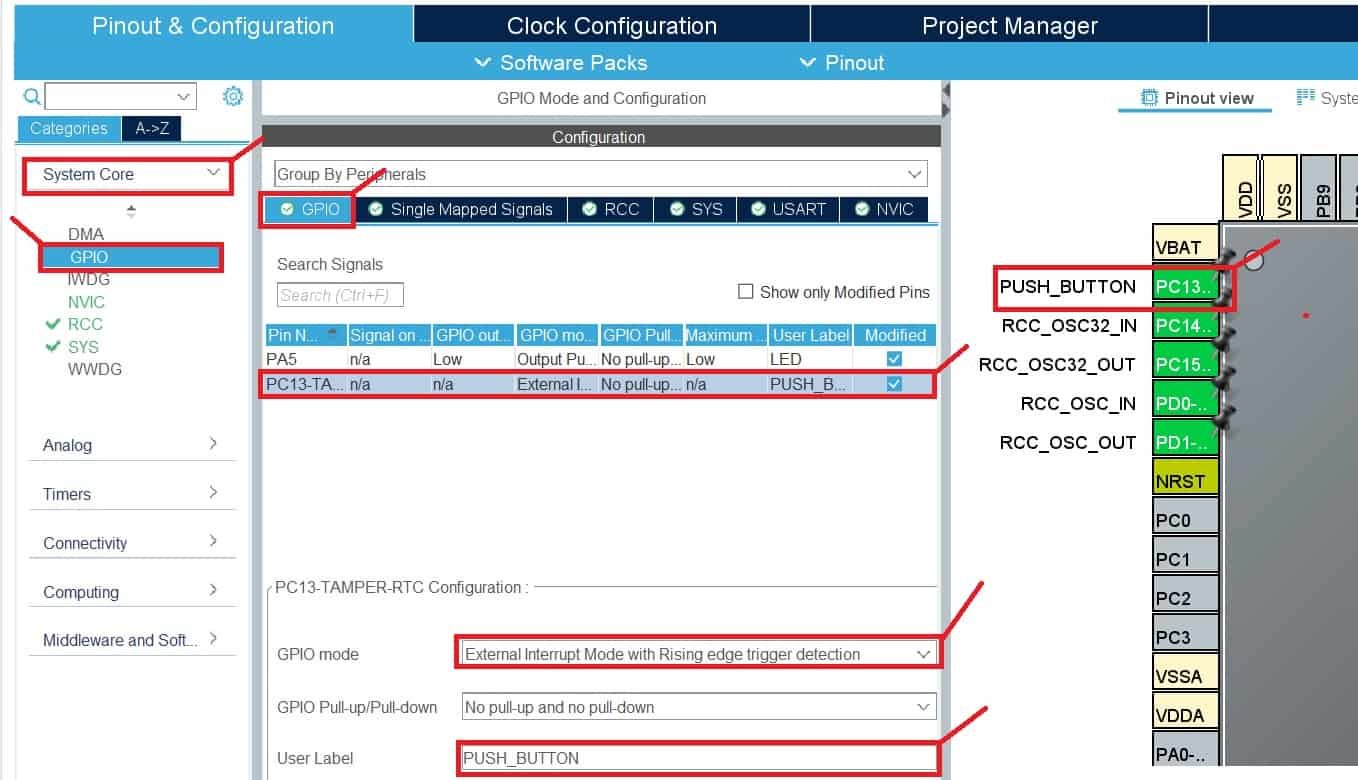
If you want to use rising edge detection mode, you can do following settings:
Now enable the interrupt mask to select PC13 for the EXT13 line.

STM32 Nucleo Clock Configuration
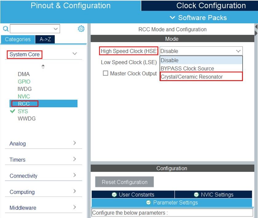
Now go to System Core > RCC then select ‘Crystal/Ceramic Resonator’ from the High-Speed Clock feature.
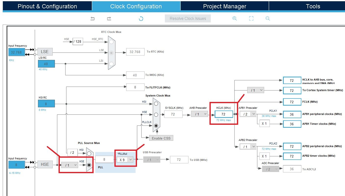
Next, go to the Clock Configuration found at the top. This will open the following window. Here we will select the clock frequency.
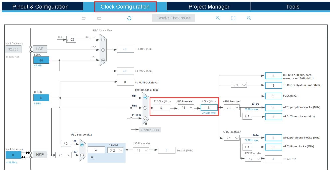
The maximum clock frequency that can be achieved for the STM32 microcontroller which comes with this STM32 Nucleo board is 72MHz. You can set clock frequency to 72MHz with following settings:
Now we will save our file. Press Ctrl + S. The following window will appear. Click ‘Yes.’ This will generate a template code for you.

Another window will appear that will ask if you want to open the perspective. Click ‘Yes.’
STM32CubeMX Generated Code
Now the following page opens. On the right side, you will be able to view the Outline of the code. In the center, you can view the main.c file and on the left, you can view the Project Explorer. If you want to go to the Device Configuration Tool, then click the External_Interrupts.ioc tab.
STM32CubeMX will add all required HAL libraries and system-level HAL libraries to use the PA5 pin of STM32 Nucleo as a digital output pin and the PC13 pin as a digital input pin with interrupt configuration.
STM32 Nucleo External Interrupt ISR
Now copy the following code and put it between /* USER CODE BEGIN 4 / and / USER CODE END 4 */ tags.
/* USER CODE BEGIN 4 */
void HAL_GPIO_EXTI_Callback(uint16_t GPIO_Pin)
{
  if(GPIO_Pin == GPIO_PIN_13) {
	  HAL_GPIO_TogglePin(GPIOA, GPIO_PIN_5);
  } else {
      __NOP();
  }
}
/* USER CODE END 4 */
In the above code, HAL_GPIO_EXTI_Callback() is a weak-defined interrupt service routine for GPIO external interrupt handlers. By defining HAL_GPIO_EXTI_Callback() function in the main.c, the compiler will replace the earlier definition with the above one.
Inside the function, there is an if statement that checks if the GPIO_Pin parameter is equal to GPIO_PIN_13. The GPIO_PIN_13 is a predefined constant in STM32Cube that represents a specific GPIO pin (in this case, pin 13).
if(GPIO_Pin == GPIO_PIN_13) If the condition in the if statement is true (i.e., the interrupt was triggered by GPIO pin 13), the code inside the if block is executed. In this case, it toggles (flips) the state of GPIO pin 5 of GPIO port A using the HAL_GPIO_TogglePin() function. This function is provided by the STM32Cube HAL to manipulate the state of a GPIO pin.
HAL_GPIO_TogglePin(GPIOA, GPIO_PIN_5);If the condition in the if statement is false (i.e., the interrupt was triggered by a different GPIO pin), the code inside the else block is executed. In this case, the __NOP() instruction is called, which is an assembly language instruction that performs no operation. It effectively does nothing and acts as a placeholder or an empty statement.
__NOP();The code snippet is placed between the USER CODE BEGIN 4 and USER CODE END 4 comments to indicate that this section is reserved for user-defined code and will not be modified by the STM32CubeIDE itself. This allows developers to add their own custom logic within these boundaries without it being overwritten during code generation or updates made by the IDE.
STM32CubeIDE Generated GPIO Interrupt Initialization Code
The following MX_GPIO_Init() function is generated by STM32CubeIDE.
static void MX_GPIO_Init(void)
{
  GPIO_InitTypeDef GPIO_InitStruct = {0};
/* USER CODE BEGIN MX_GPIO_Init_1 */
/* USER CODE END MX_GPIO_Init_1 */

  /* GPIO Ports Clock Enable */
  __HAL_RCC_GPIOC_CLK_ENABLE();
  __HAL_RCC_GPIOD_CLK_ENABLE();
  __HAL_RCC_GPIOA_CLK_ENABLE();
  __HAL_RCC_GPIOB_CLK_ENABLE();

  /*Configure GPIO pin Output Level */
  HAL_GPIO_WritePin(LED_GPIO_Port, LED_Pin, GPIO_PIN_RESET);

  /*Configure GPIO pin : PUSH_BUTTON_Pin */
  GPIO_InitStruct.Pin = PUSH_BUTTON_Pin;
  GPIO_InitStruct.Mode = GPIO_MODE_IT_RISING;
  GPIO_InitStruct.Pull = GPIO_NOPULL;
  HAL_GPIO_Init(PUSH_BUTTON_GPIO_Port, &GPIO_InitStruct);

  /*Configure GPIO pin : LED_Pin */
  GPIO_InitStruct.Pin = LED_Pin;
  GPIO_InitStruct.Mode = GPIO_MODE_OUTPUT_PP;
  GPIO_InitStruct.Pull = GPIO_NOPULL;
  GPIO_InitStruct.Speed = GPIO_SPEED_FREQ_LOW;
  HAL_GPIO_Init(LED_GPIO_Port, &GPIO_InitStruct);

  /* EXTI interrupt init*/
  HAL_NVIC_SetPriority(EXTI15_10_IRQn, 0, 0);
  HAL_NVIC_EnableIRQ(EXTI15_10_IRQn);

/* USER CODE BEGIN MX_GPIO_Init_2 */
/* USER CODE END MX_GPIO_Init_2 */
}
You don’t need to modify any things in this function. We just want to show you how STM32CubeIDE configures the NVIC for the EXTI controller. The HAL_NVIC_SetPriority() function sets the priority for EXTI15_10 and HAL_NVIC_EnableIRQ() enables a device specific interrupt in the NVIC interrupt controller.
 HAL_NVIC_SetPriority(EXTI15_10_IRQn, 0, 0);
 HAL_NVIC_EnableIRQ(EXTI15_10_IRQn);
Building the Project
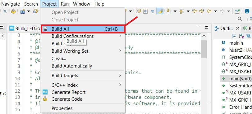
To build a project press Ctrl + B or go to Project > Build All.
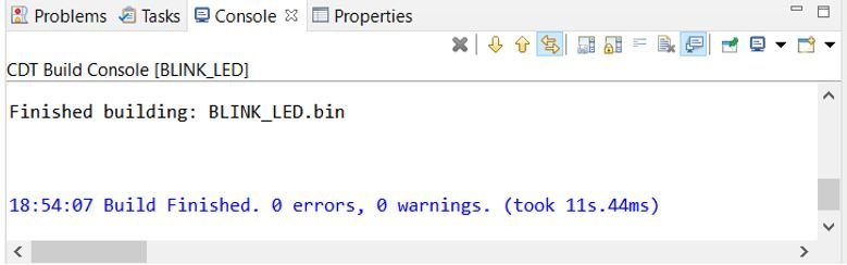
Your project will start building. After a few moments, your project will be built if there are no errors.
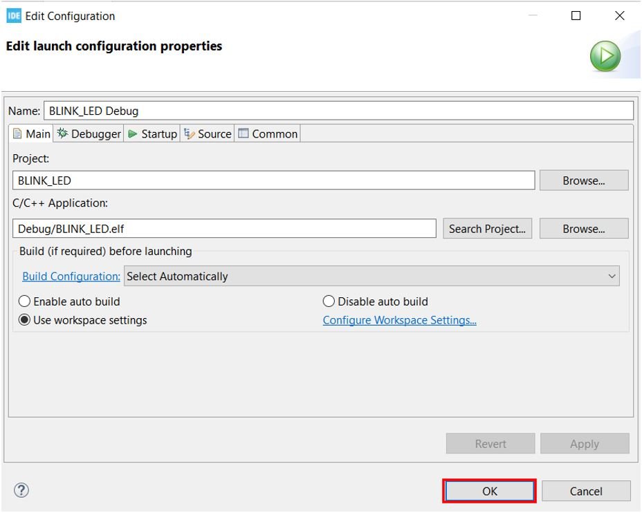
Connect STM32 Nucleo with your computer and next press the RUN button in the IDE. The following ‘Edit configuration’ window will open up. Click ‘OK’.
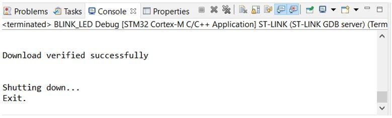
After a few moments, the code will be successfully sent to the STM32 board. You can view it in the Console terminal.
Otherwise, press the RESET button on your STM32 board.
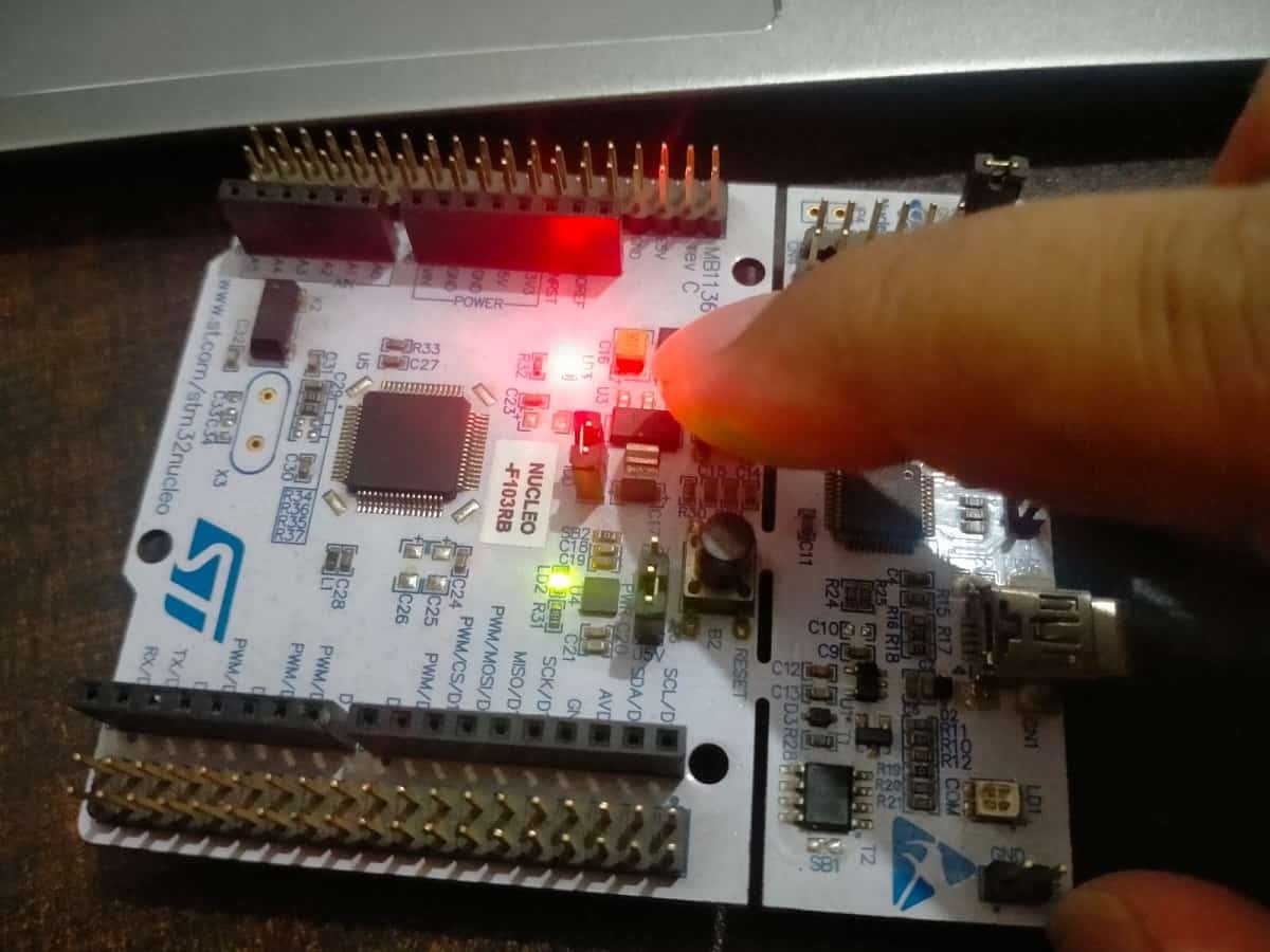
Press the black color reset button on the STM32 Nucleo board. Now if you press the blue button on the STM32 Nucleo board, the onboard LED state will toggle from ON to OFF and if you press it again LED will change from OFF to ON.
When you press the push button, the PC13 pin detects a falling edge and HAL_GPIO_EXTI_Callback() function executes which toggles the state of onboard LED of STM32 Nucleo.

Recommended Components
The following components are used in this project or are helpful for getting started with STM32 Nucleo development.
| Component | How it’s used in this project | Buy on Amazon |
|---|---|---|
| STM32 Nucleo Board (NUCLEO-F103RB) | The STM32 Nucleo-64 development board used in this guide. | Check Price |
| Micro USB / Mini-B USB Cable | Type-A to Mini-B cable to program and power the Nucleo over its onboard ST-Link. | Check Price |
As an Amazon Associate we earn from qualifying purchases. Prices and availability are accurate as of the date/time indicated and are subject to change.
Conclusion
In conclusion, this tutorial has thoroughly explored the use of GPIO interrupts, or external interrupts, on the STM32 Nucleo board. By learning how to configure interrupts for edge-triggered and level-triggered modes, you now have the tools to handle various input events efficiently. Whether you need to respond to positive or negative edges or specific active high or low levels, understanding these configurations allows for more responsive and dynamic applications. This foundational knowledge of GPIO interrupts will enable you to develop more sophisticated and reactive systems in your STM32 projects.
Other STM32 Nucleo tutorials:
- HC-SR04 Ultrasonic Sensor with STM32 Nucleo using STM32CubeIDE
- SSD1306 OLED with STM32 Nucleo using STM32CubeIDE
- HC-05 Bluetooth Module with STM32 Nucleo using STM32CubeIDE
- STM32 Nucleo Timer in Counter Mode with STM32CubeIDE and HAL Libraries
- STM32 Nucleo Timer Encoder Mode with Rotary Encoder Example
- STM32 Nucleo Generate PWM with Timers using STM32CubeIDE
You may also like to read:
- STM32 Blue Pill External Interrupts with STM32Cube IDE and HAL Libraries
- GPIO Interrupts TM4C123 Tiva Launchpad – External Interrupts
- PIR Motion Sensor with Raspberry Pi Pico using External Interrupts
- What is Interrupt Vector Table?
- FreeRTOS Interrupt Management Examples with Arduino
- ESP32 External Interrupts using Arduino IDE
Following your tutorial with a C031C06 nucleo board, everything seems to work good, but when I try to build, I see STM32CubeIDE has generated this line:
HAL_EXTI_IRQHandler(&H_EXTI_13);
inside void EXTI4_15_IRQHandler(void) function in stm32c0xx_it.c. The problem now is when try to compile, H_EXTI_13 is undeclared, and therefore it fails to compile.
Any idea of what is happening?