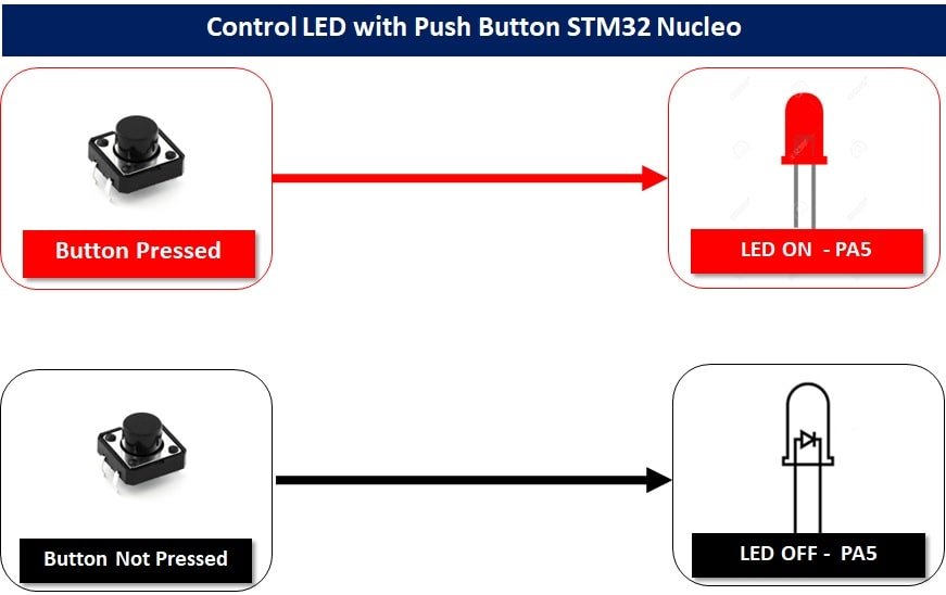
In this tutorial, we will learn to use the GPIO pins of STM32 Nucleo board as digital input pins. In the last tutorial, we have seen how to use GPIO pins as digital output pins. For demonstration, we will also show how to interface a push button with the STM32 Nuclro and read the state of a push button. Furthermore, if the push button is pressed onboard LED will turn on, and otherwise LED remains off.
Push Button Interfacing with STM32 Nucle
When we want to interface a push button with a microcontroller, we actually want to read the state of the push button either pressed or not pressed state. When a push button is pressed or unpressed, it provides either logic high or logic low output depending on the configuration mode in which the push button circuit is designed.
There are two configuration modes to interface a push button with STM32 Nucleo board. Let’s discuss both these modes one by one.
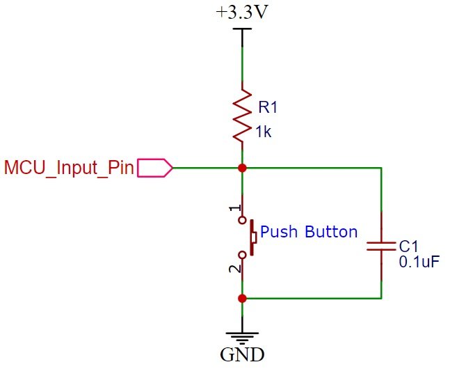
Pull-Up Mode
In Pull-up mode, when a push button is not pressed, a logic high input appears at MCU_Input_Pin. Because a 3.3V signal appears on the input terminal through an R1 resistor. On the contrary, when the push button is pressed, metallic contacts of the push button make contact with the ground terminal and the input terminal. Therefore, a logic low input will reflect on the digital input pin of the STM32 Nucleo board. In short, by reading this state of the push button with a digital input pin of a microcontroller, we can identify whether a push button is pressed or not. The following schematic diagram shows the connection of a push button with a pull-up resistor.
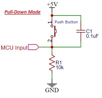
Pull-Down Mode
In Pull-down mode, when a push button is not pressed, a logic low input appears on the STM32 Nucleo GPIO pin. Because a ground reference signal appears on the input terminal through an R1 resistor. On the contrary, when the push button is pressed, metallic contacts of the push button make contact with the +5V signal and the input terminal. Therefore, a logic high input reflects on the digital input pin of STM32 Nucleo board. The following schematic diagram shows the connection of a push button with a pull-down resistor.
Internal Pull-up and Pull-down Resistors STM32 Microcontrollers
STM32 microcontroller’s GPIO ports also have internal pull-up and pull-down resistors which can be configured through the PUPDR register. In HAL libraries, these internal pull-ups and pull-down resistors can be configured through the GPIO_InitTypeDef struct by passing corresponding values to Pull member of the GPIO_InitTypeDef C struct. In STM32CubeIDE, we will configure it through a GUI tool.
typedef struct
{
  uint32_t Pin;       /*!< Specifies the GPIO pins to be configured.
                           This parameter can be any value of @ref GPIO_pins_define */

  uint32_t Mode;      /*!< Specifies the operating mode for the selected pins.
                           This parameter can be a value of @ref GPIO_mode_define */

  uint32_t Pull;      /*!< Specifies the Pull-up or Pull-Down activation for the selected pins.
                           This parameter can be a value of @ref GPIO_pull_define */

  uint32_t Speed;     /*!< Specifies the speed for the selected pins.
                           This parameter can be a value of @ref GPIO_speed_define */

  uint32_t Alternate;  /*!< Peripheral to be connected to the selected pins.
                            This parameter can be a value of @ref GPIO_Alternate_function_selection */
}GPIO_InitTypeDef;
These values which can be passed to Pull members are:
#define  GPIO_NOPULL        0x00000000U /*!< No Pull-up or Pull-down activation */
#define  GPIO_PULLUP        0x00000001U  /*!< Pull-up activation                */
#define  GPIO_PULLDOWN      0x00000002U /*!< Pull-down activation        */
But for the demonstration purpose, we will use the onboard push button of STM32 NUCLEO-F103RB. But you can also use an external push button in any one of the above configurations.
STM32 Nucleo OnBoard Push Button
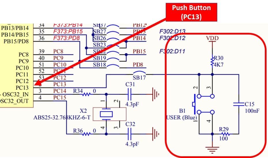
Almost all STM32 Nucleo boards come with one user push button connected. In STM32 NUCLEO-F103RB, this push button is connected to the PC13 GPIO pin. We will use this push button as a digital input to control onboard LEDs on the discovery board.
As you can see in the following schematic diagram, the onboard user push button is connected to PC13 digital pin through a pull-up resistor. This means when the push button is not pressed, we will get an active high signal at the PC13 pin. Similarly, when it is pressed, we will get an active low signal on the PC13 pin.
To use this button, we should configure the PA0 pin of GPIOA as a digital input pin.
Controlling LEDs with Push Button STM32F4
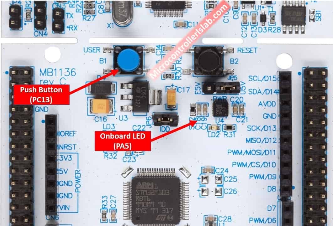
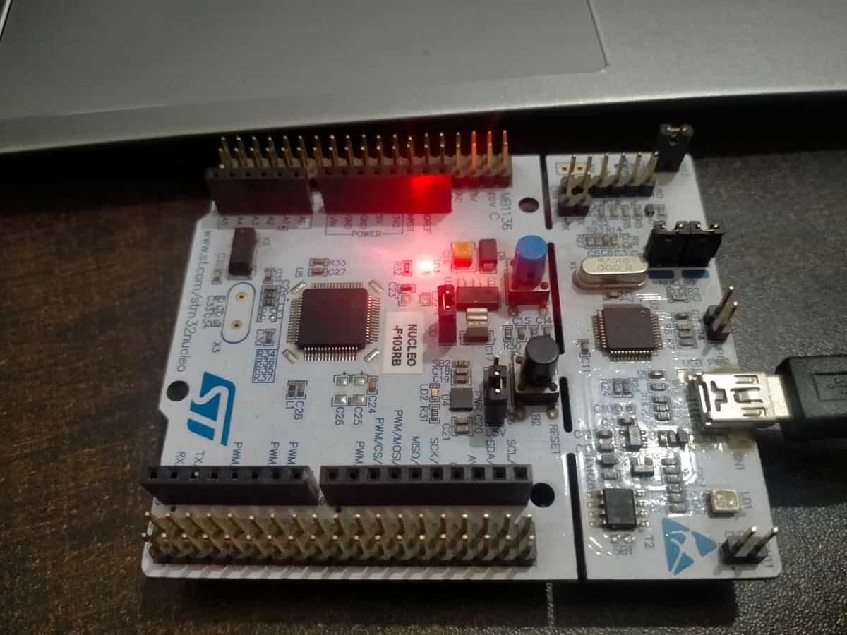
For demonstration purposes, we will control the onboard LED of STM32 Nucleo board with a push button. As you can see in the figure shown below a blue color push button is available along with one green LED.
In the last tutorial, we learned to control onboard LED, If you don’t know how to configure GPIO pins as digital output pins, you should read that tutorial from this link:
In this tutorial, we will demonstrate the following example:
- PC13 pin will read the output of the push button, if the state is active low, it will turn on the onboard LED of STM32 Nucleo. Because the push button is connected with the PC13 pin in pull-up configuration and under normal conditions active high output will appear on the PC13 pin.
- When the push button is pressed, LED will be on, otherwise LED will remain off.
First, let’s see how to write the first program for STM32 Nucleo in STM32CubeIDE.
Create STM32 Nucleo Push Button Interfacing STM32CubeIDE Project
After installing STM32CubeIDE on your Windows, Linux, or MacOS system, follow these steps to create a project. In this section, you will learn the followings:
- create and configure the STM32CubeMX project and generate the initialization code
- program and use HAL functions to read the push button state and control the LED on the NUCLEO-F103RB board.
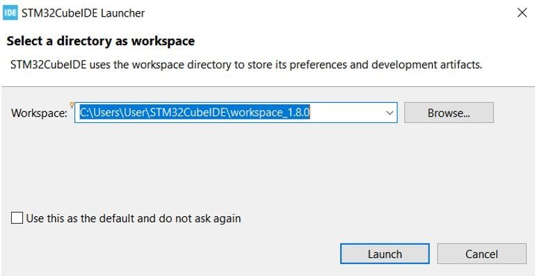
Launch STM32CubeIDE: Open the STM32CubeIDE application on your computer. You will be asked to specify the directory for the workplace. You can specify the directory and also tick the box below to keep this as the default directory. Next, click ‘Launch’ to start the application.
The STM32Cube workspace will open. Now click ‘Start new STM32 project’.

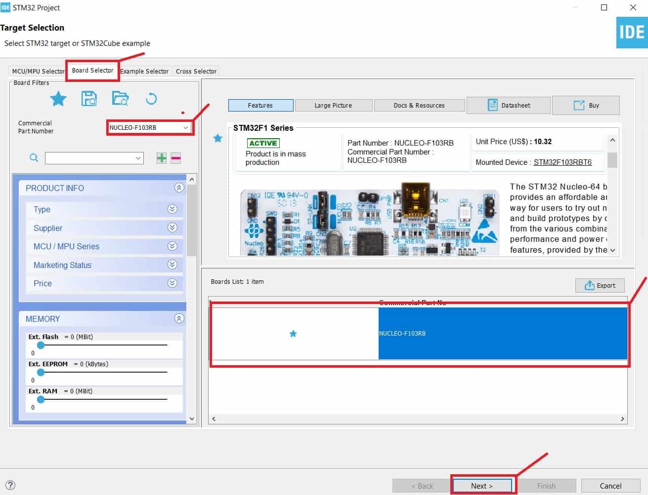
From Board Selector section, type STM32 Nucleo-F103RB and select it. Click next.
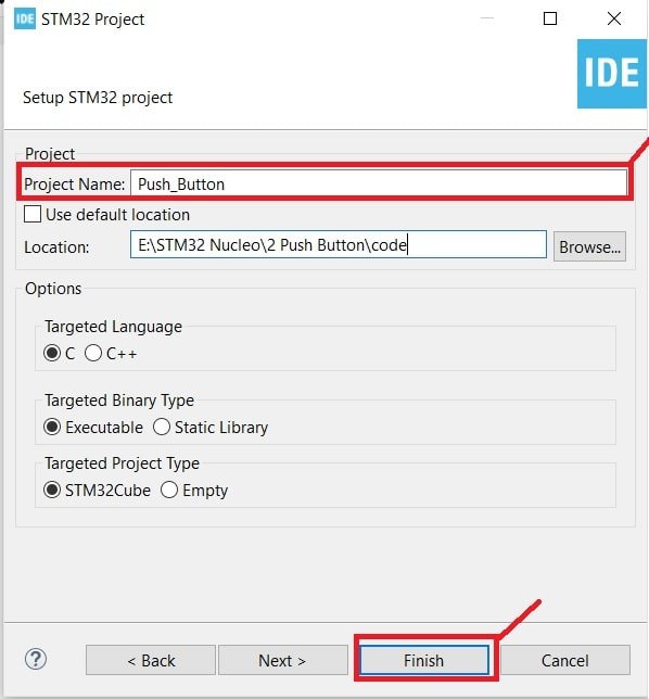
Give your project a name. As we are going to blink the on-board LED of STM32 Nucleo-F103RB hence we have named our project ‘BLINK_LED.’ Then click ‘Finish.’
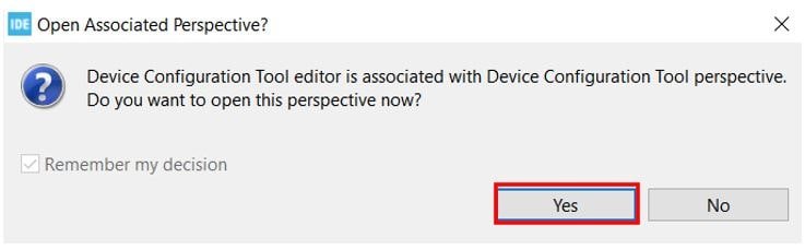
You will be asked to open an associated perspective to start generating code with STM32CubeMX. Click ‘Yes’.
STM32 Nucleo GPIO Pins Configiuration
Now the Device Configuration Tool window will open up. In the pinout and configuration window, we can select a specific pin and its function. A single GPIO pin may have multiple alternate functions. For example, the same GPIO pin can be used for ADC, SPI, UART peripherals, etc. But only one function can be used at a time.
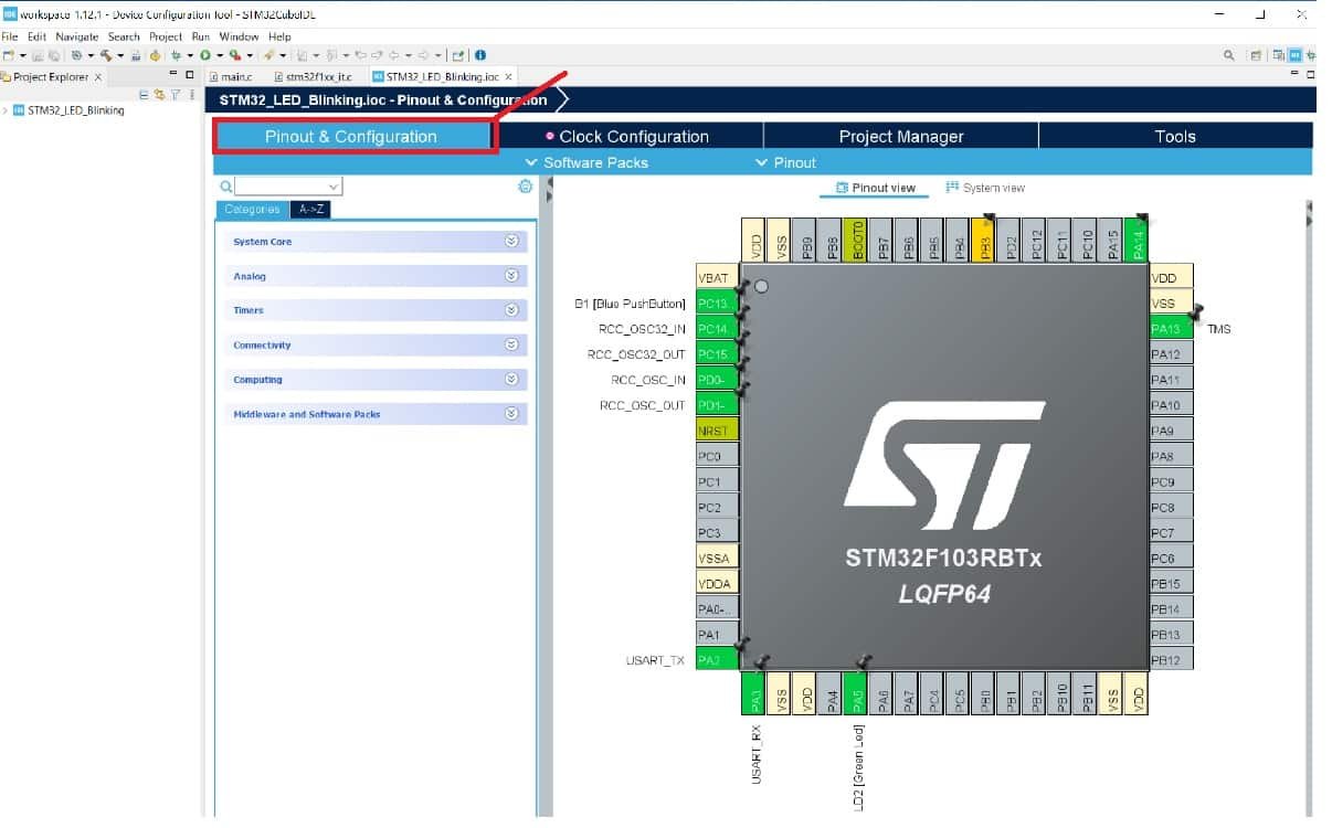
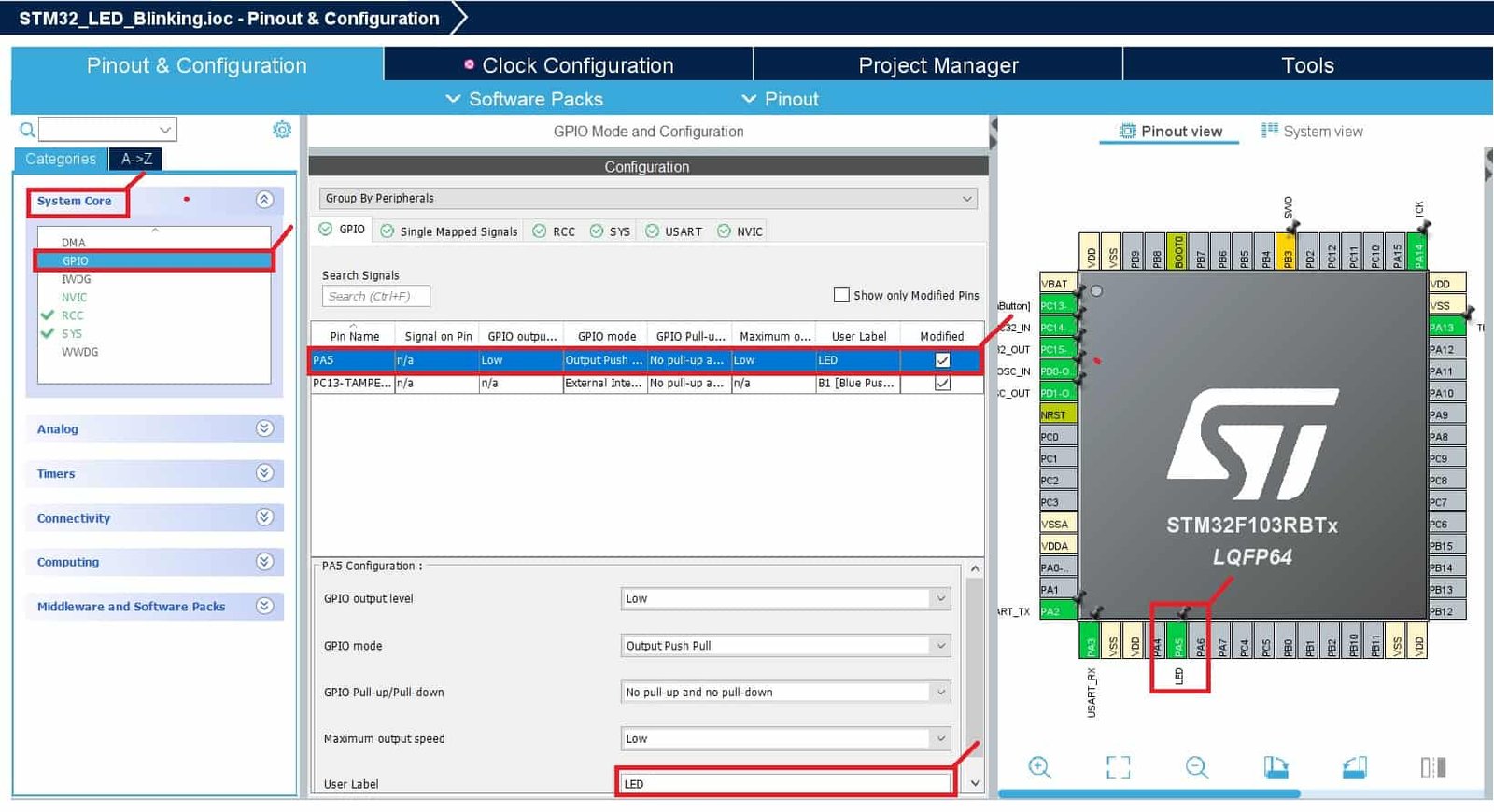
As mentioned earlier, we will use an onboard LED of STM32 Nucleo-F103RB board. The onboard LED of Nucleo-F103RB board is connected with a PA5 pin. When you create a project for Nucleo-F103RB, you will see that it has already been configured for the PA5 pin. But you can change it according to your requirement.
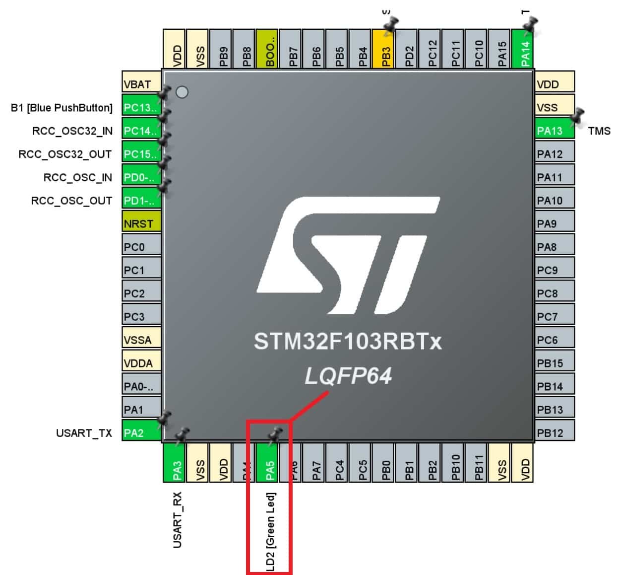
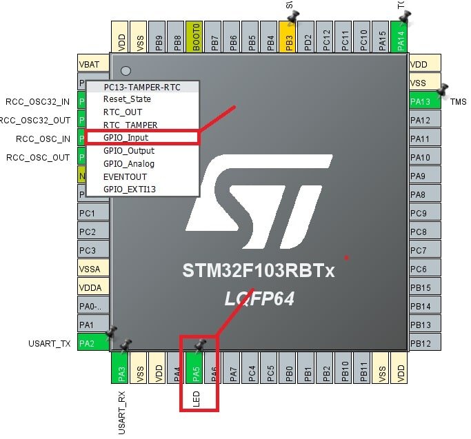
Click on the PA5 pin, and a list of all alternate functions will appear associated with the PA5 pin. We will set this pin as a ‘GPIO Output.’
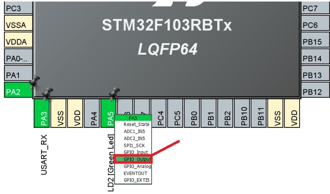
This is how it will look. Here you can see that we have attached GPIO_Output to PA5.
Additionally, we have more options for pins as well. Go to System Core > GPIO > PA5 and the pin configuration for PA5 will open up. Here we have given the pin a user label of ‘LED.’ You can see in Device Configuration Tool, that now PA5 has been given the label ‘LED.’
Apart from the label, there are several other options to choose from including GPIO output level, mode, pull-up/pull-down state, etc.
In the GPIO Tab, select Pin Name column PA5 to display the corresponding GPIO parameters and configuration to drive the Nucleo-F103RB LED:
- GPIO Output level: By default, the output level is set to Low, meaning the pin is at a low voltage. However, you can change it to High if needed.
- GPIO mode: The mode automatically configures the pins with the appropriate alternate function and sets them to Output Push Pull mode, ensuring compatibility and stability.
- GPIO Pull-up/Pull-down: By default, no pull-up or pull-down resistors are enabled. However, depending on your requirements, you can configure pull-up or pull-down options if supported by the specific pin.
- GPIO Maximum output speed: The maximum output speed is initially set to Low for power consumption optimization. However, if your application requires a higher frequency, you can change this setting accordingly.
- User Label: This is a customizable name assigned to a GPIO pin for easier identification and access. You can assign a meaningful label, and later use the Find menu to locate and work with the GPIO pin based on its label.
These configurations and parameters allow you to customize the behavior of the GPIO pins to suit the needs of your specific project and ensure proper functionality.
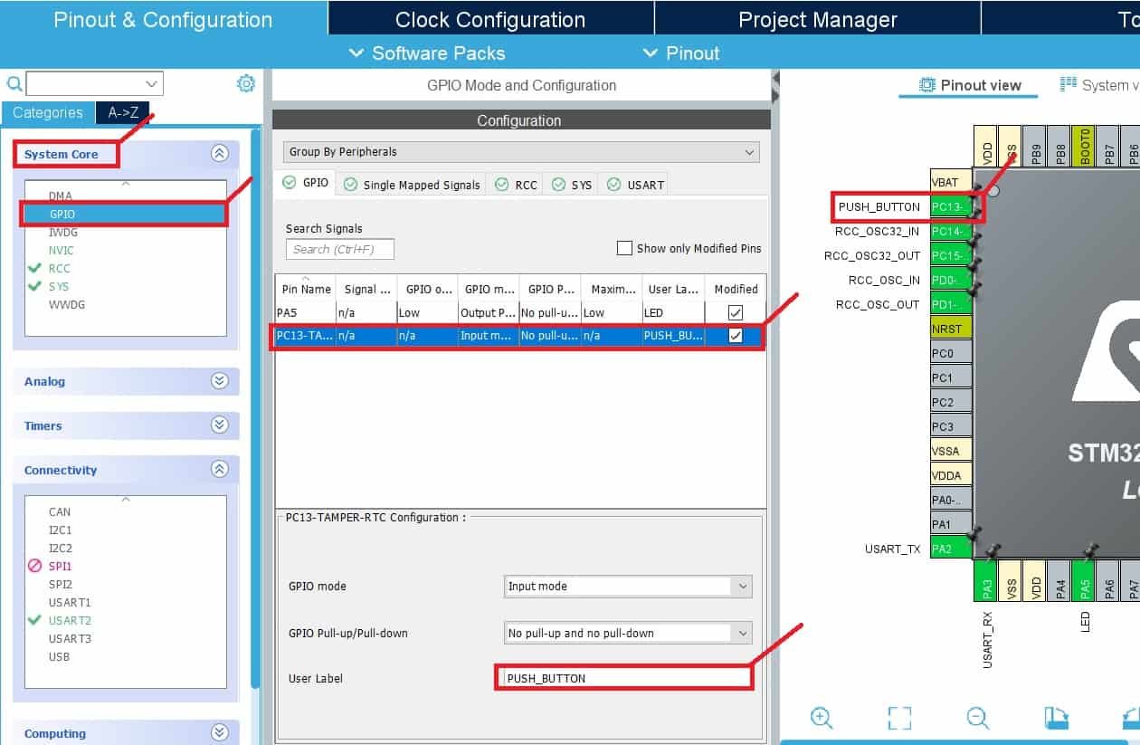
Now select PC13 pin as a digital input pin by selecting option GPIO_INPUT as shown below:
Also, go to System Core > GPIO > PC13 and the pin configuration for PC13 will open up. Here, give the label to the PC13 pin by giving it whatever name you want. You will see in Device Configuration Tool, that now PC13 will be labeled accordingly.
Furthermore, as you can see we have not selected a Pull-up or pull-down resistor from GPIO Pull-up/Pull-down option. Because the onboard push button of STM32 Nucelo already has an external pull-up resistor connected to it.
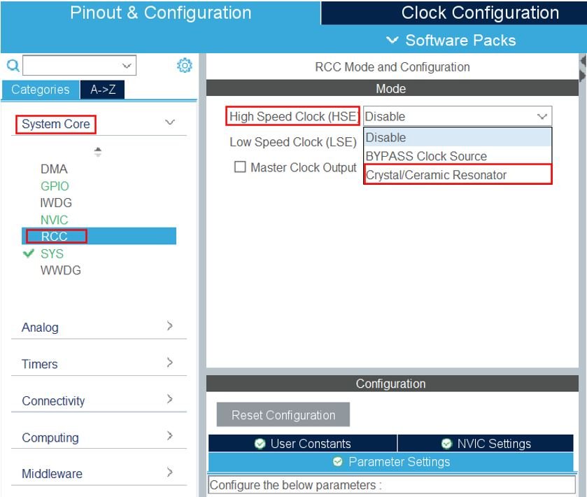
STM32 Nucleo Clock Configuration
Now go to System Core > RCC then select ‘Crystal/Ceramic Resonator’ from the High-Speed Clock feature.
Next, go to the Clock Configuration found at the top. This will open the following window. Here we will select the clock frequency.
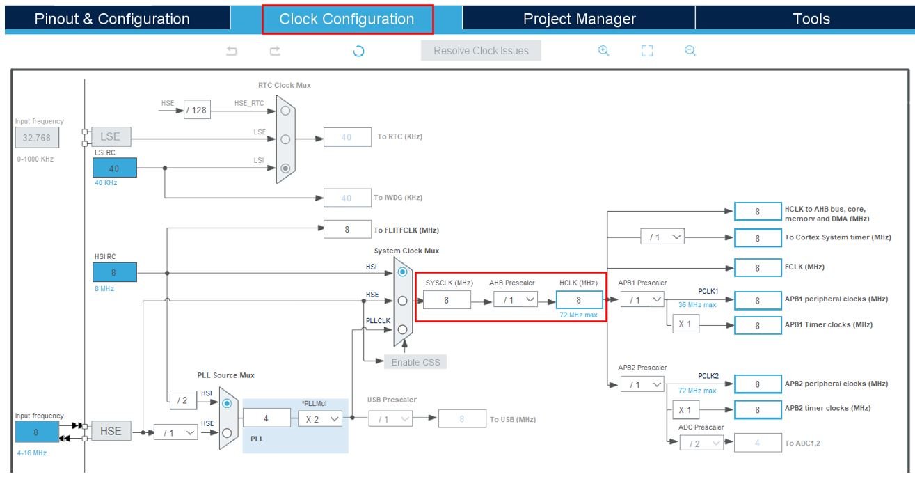
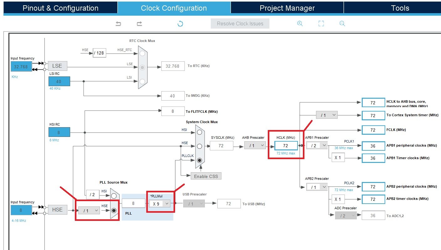
The maximum clock frequency that can be achieved for the STM32 microcontroller which comes with this STM32 Nucleo board is 72MHz. You can set clock frequency to 72MHz with following settings:
Now we will save our file. Press Ctrl + S. The following window will appear. Click ‘Yes.’ This will generate a template code for you.

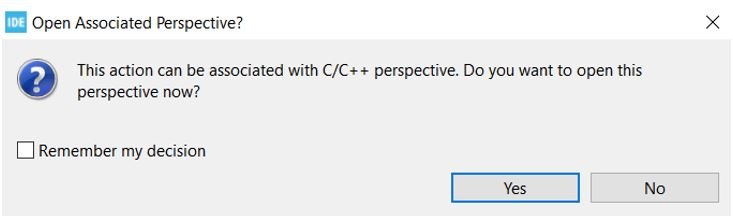
Another window will appear that will ask if you want to open the perspective. Click ‘Yes.’
STM32CubeMX Generated Code
Now the following page opens. On the right side, you will be able to view the Outline of the code. In the center, you can view the main.c file and on the left, you can view the Project Explorer. If you want to go to the Device Configuration Tool, then click the Push_Button.ioc tab.
STM32CubeMX will add all required HAL libraries and system-level HAL libraries to use the PA5 pin of STM32 Nucleo as a digital output pin and the PC13 pin as a digital input pin.
STM32 Nucleo Push Button Code
Now let’s modify the main.c file for our Push_Button project. Our target is that the PC13 pin will read the output of the push button, if the output state is active low, we will turn on the onboard LED of STM32 Nucleo. Because the push button is connected with the PC13 pin in pull-up configuration and otherwise LED will remain off.
First, inside the main() function go to while(1) and insert the following lines of code. This code checks the state of the GPIO pin 13 of the GPIOC port. If it is in the reset state or active low, it turns on an LED by setting the GPIO pin 5 of the GPIOA port to the high state. Otherwise, it turns off the LED by setting the GPIO pin 5 to the low state.
/* USER CODE END WHILE */
	 if(HAL_GPIO_ReadPin (GPIOC, GPIO_PIN_13) == GPIO_PIN_RESET)
	 {
	 	  //Turn LED ON
		 HAL_GPIO_WritePin(GPIOA, GPIO_PIN_5, GPIO_PIN_SET);
	 }
	 else
	 {
	 	  //Turn LED OFF
	 	  HAL_GPIO_WritePin(GPIOA, GPIO_PIN_5, GPIO_PIN_RESET);
	 }
    /* USER CODE BEGIN 3 */
Save the main.c file after modifying it. Now we are ready to build our project.
Now let’s see the what above code does and what each function does.
The HAL_GPIO_ReadPin function is available in the Hardware Abstraction Layer (HAL) library of STM32. It reads the state of a specific pin of the STM32 microcontroller, in this case, pin 13 of GPIOC (GPIO port C). It returns the state of the pin, which can be either GPIO_PIN_SET or GPIO_PIN_RESET.
HAL_GPIO_ReadPin(GPIOC, GPIO_PIN_13)The HAL_GPIO_WritePin function is also provided by the HAL library. It sets the state of a specific pin, in this case, pin 5 of GPIOA (GPIO port A), to the high state. It turns on the LED connected to that pin. The GPIO_PIN_SET constant is used to specify the high state.
HAL_GPIO_WritePin(GPIOA, GPIO_PIN_5, GPIO_PIN_RESET)Similar to the previous function, this function sets the state of pin 5 of GPIOA to the active low state. It turns off the LED connected to that pin. The GPIO_PIN_RESET constant is used to specify the low state.
//Turn LED OFF
HAL_GPIO_WritePin(GPIOA, GPIO_PIN_5, GPIO_PIN_RESET);
The HAL library provides an abstraction layer for interacting with the hardware, making it easier to write platform-independent code. It encapsulates low-level hardware access and provides higher-level functions to interact with GPIO pins.
Building the Project
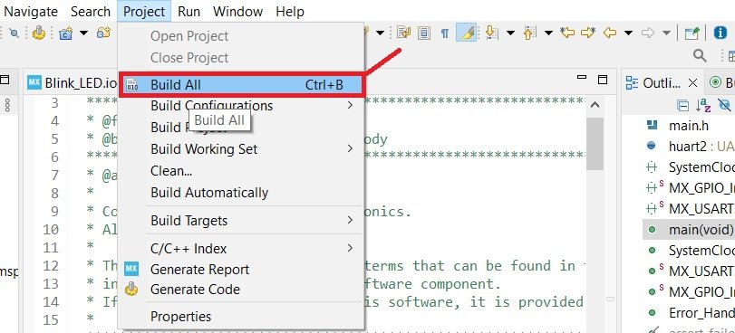
To build a project press Ctrl + B or go to Project > Build All.
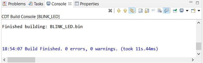
Your project will start building. After a few moments, your project will be built if there are no errors.
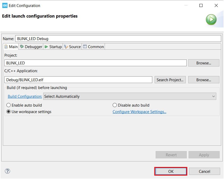
Connect STM32 Nucleo with your computer and next press the RUN button in the IDE. The following ‘Edit configuration’ window will open up. Click ‘OK’.
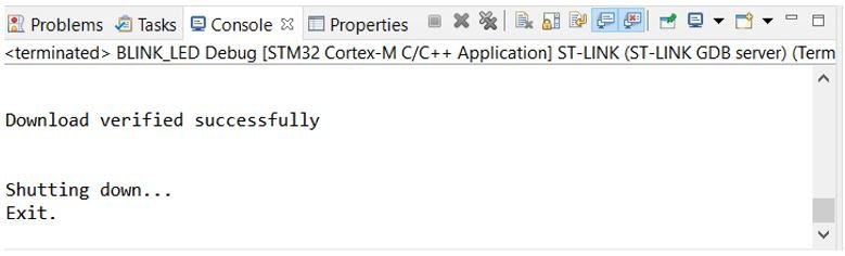
After a few moments, the code will be successfully sent to the STM32 board. You can view it in the Console terminal.
Otherwise, press the RESET button on your STM32 board.
Press the black color reset button on the STM32 Nucleo board. Now if you press the blue button on STM32 Nucleo board, the onboard LED will turn on and as soon as you release the button, LED will turn off.
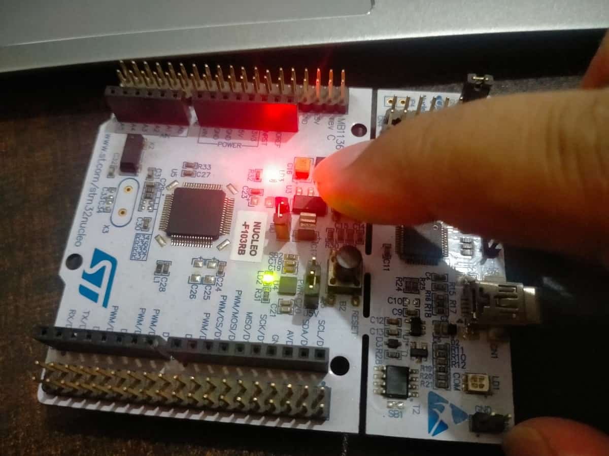
LED is off when the push button is not pressed:
Conclusion
In conclusion, this tutorial has provided a comprehensive guide on how to use the GPIO pins of the STM32 Nucleo board as digital input pins. By interfacing a push button, we demonstrated how to read its state and control the onboard LED based on whether the button is pressed or not. The two configuration modes for push button interfacing offer flexibility depending on the desired logic level output. With this knowledge, you can expand your understanding of input handling on STM32 boards and apply similar techniques for more complex input devices in your projects.
Recommended Components
The following components are used in this project or are helpful for getting started with STM32 Nucleo development.
| Component | How it’s used in this project | Buy on Amazon |
|---|---|---|
| STM32 Nucleo Board (NUCLEO-F103RB) | The STM32 Nucleo-64 development board used in this guide. | Check Price |
| Micro USB / Mini-B USB Cable | Type-A to Mini-B cable to program and power the Nucleo over its onboard ST-Link. | Check Price |
As an Amazon Associate we earn from qualifying purchases. Prices and availability are accurate as of the date/time indicated and are subject to change.
Other STM32 Nucleo tutorials:
- GPIO External Interrupts STM32 Nucleo with STM32CubeIDE
- STM32 Nucleo UART Communication Tutorial with CubeIDE and HAL Libraries
- STM32 Nucleo UART Interrupt with STM32CubeIDE and HAL Libraries
- STM32 Nucleo UART DMA with STM32CubeIDE and HAL Libraries
- STM32 Nucleo Timer Interrupt with STM32CubeIDE and HAL Libraries
- STM32 Nucleo Timer Input Capture Mode with Frequency Measurement Example
You may also like to read: