This STM32F4 Discovery Board push button tutorial shows you how to interface a push button with the STM32F4 Discovery Board and use it to control the four onboard LEDs. In practice this means configuring a GPIO pin of the STM32F407VG microcontroller as a digital input pin using the HAL (Hardware Abstraction Layer) library and Keil uvision IDE, reading its state in a loop, and driving the onboard LEDs (PD12–PD15) based on whether the button is currently pressed. Reading a push button is the natural next step after LED blinking with STM32F4 GPIO pins, because it introduces the two most important concepts for every input peripheral on the STM32: pull-up/pull-down resistors and the HAL_GPIO_ReadPin() function.
By the end of this push button tutorial you will understand how pull-up and pull-down configurations change the idle state of a GPIO input, how the onboard user button (B1) on the STM32F4 Discovery Board is wired to PA0 through an external pull-down, how to configure PA0 as a digital input using the HAL GPIO driver, and how to combine digital input and digital output to create the simplest kind of event-driven embedded application.

What You Will Learn
- How a push button produces a readable digital signal — the role of pull-up and pull-down resistors
- The difference between pull-up and pull-down wiring, with schematic diagrams of both
- How to use the internal pull-up and pull-down resistors of the STM32F407VG through the HAL
Pullparameter - How the onboard user button B1 is connected to PA0 on the STM32F4 Discovery Board
- How to configure PA0 as a digital input pin using
GPIO_InitTypeDefandHAL_GPIO_Init() - How to read the push button state using
HAL_GPIO_ReadPin()and theGPIO_PinStateenum - How to combine digital input (push button) with digital output (LEDs) in a single main loop
- Common push button troubleshooting issues like switch bouncing and floating inputs
Prerequisites and Required Components
- STM32F4 Discovery Board (STM32F407G-DISC1) — provides both the user push button (B1) and the four user LEDs
- Mini USB cable for the onboard ST-LINK/V2 (programming and power)
- Keil uvision IDE with the STM32F4 device family pack installed
- Basic familiarity with the STM32F4 LED blinking tutorial (this guide reuses that exact GPIO output code)
Because the Discovery Board already has the user button wired to PA0 with an external pull-down resistor, you do not need any breadboard, jumper wires, or external components for this push button tutorial.
Push Button Interfacing with STM32F4 Discovery Board
When we interface a push button with a microcontroller, what we actually want to do is read the state of the button — pressed or not pressed. A mechanical push button on its own does not produce a voltage. It is simply a switch that either connects or disconnects two contacts. To get a clean digital signal out of it, the button must be wired together with a resistor in one of two standard configurations. When the button is pressed or released, the resulting GPIO pin will read either logic HIGH or logic LOW depending on which configuration you chose.
There are two standard configurations for interfacing a push button with the STM32F4 Discovery Board: pull-up and pull-down. Let’s look at each one.
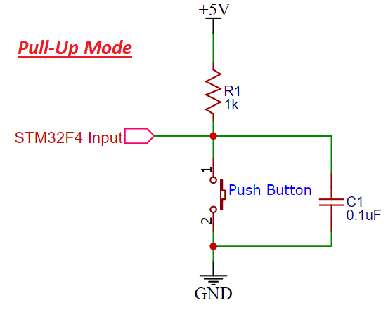
Pull-Up Mode
In pull-up mode, when the push button is not pressed, a logic HIGH appears on the STM32F4 GPIO pin because the 3.3 V supply reaches the input through the pull-up resistor R1. When the push button is pressed, the metallic contacts short the GPIO pin to ground, pulling the input line LOW. So in a pull-up configuration:
- Button released → GPIO reads HIGH (logic 1)
- Button pressed → GPIO reads LOW (logic 0)
By reading the state of this GPIO pin with the STM32F4 HAL GPIO driver, we can detect whether the button is pressed. The schematic below shows a push button wired with a pull-up resistor.
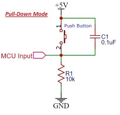
Pull-Down Mode
In pull-down mode, when the push button is not pressed, a logic LOW appears on the STM32F4 GPIO pin because the input line is tied to ground through R1. When the push button is pressed, the metallic contacts connect the 3.3 V (or 5 V) rail to the GPIO pin, producing a logic HIGH input. So in a pull-down configuration:
- Button released → GPIO reads LOW (logic 0)
- Button pressed → GPIO reads HIGH (logic 1)
The schematic below shows a push button wired with a pull-down resistor. This is the exact configuration used by the onboard user button on the STM32F4 Discovery Board.
Never leave a GPIO input pin floating. A floating input (no pull resistor and no active driver) picks up stray noise from your hands, nearby wires, and the power supply. The pin will read random 1s and 0s, and your program will behave unpredictably. Always terminate every push button with either a pull-up or pull-down resistor.
Internal Pull-Up and Pull-Down Resistors on the STM32F4
The STM32F407VG GPIO ports include internal pull-up and pull-down resistors that can be configured through the PUPDR register. This is one of the most useful features of STM32 GPIO — you can drop the external resistor entirely for most push button designs and just enable the internal pull. In HAL libraries, these internal pull-ups and pull-downs are selected through the GPIO_InitTypeDef struct by passing the appropriate value to the Pull member.
typedef struct
{
  uint32_t Pin;       /*!< Specifies the GPIO pins to be configured.
                           This parameter can be any value of @ref GPIO_pins_define */

  uint32_t Mode;      /*!< Specifies the operating mode for the selected pins.
                           This parameter can be a value of @ref GPIO_mode_define */

  uint32_t Pull;      /*!< Specifies the Pull-up or Pull-Down activation for the selected pins.
                           This parameter can be a value of @ref GPIO_pull_define */

  uint32_t Speed;     /*!< Specifies the speed for the selected pins.
                           This parameter can be a value of @ref GPIO_speed_define */

  uint32_t Alternate;  /*!< Peripheral to be connected to the selected pins.
                            This parameter can be a value of @ref GPIO_Alternate_function_selection */
}GPIO_InitTypeDef;
The three values you can pass to the Pull member are:
#define  GPIO_NOPULL        0x00000000U /*!< No Pull-up or Pull-down activation */
#define  GPIO_PULLUP        0x00000001U  /*!< Pull-up activation                */
#define  GPIO_PULLDOWN      0x00000002U /*!< Pull-down activation        */
For the onboard push button on the STM32F4 Discovery Board there is already an external pull-down resistor on the PCB, so we pass GPIO_NOPULL and let the external resistor do its job. If you are wiring your own push button on a breadboard, you can skip the external resistor entirely and use GPIO_PULLUP or GPIO_PULLDOWN to enable the internal resistor.
Onboard Push Button on the STM32F4 Discovery Board
The Discovery Board provides one user-accessible push button — the blue button labeled B1 (also called USER) — connected to PA0, pin 0 of PORTA. We will use this button as a digital input to control the four onboard LEDs.
As the schematic below shows, the onboard user button is wired to PA0 through an external pull-down resistor. This means:
- Button not pressed → PA0 reads LOW (active-low idle state)
- Button pressed → PA0 reads HIGH (active-high when pressed)
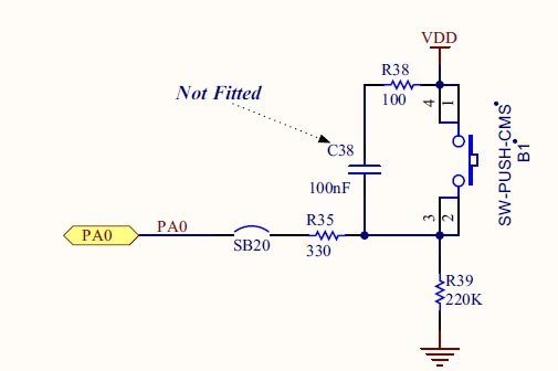
To use this button in our program, we need to configure the PA0 pin of GPIOA as a digital input pin.
Controlling LEDs with the Push Button on the STM32F4 Discovery Board
For this demonstration we will control the four onboard LEDs of the STM32F4 Discovery Board using the onboard push button. As the figure below shows, the blue user push button sits next to the four user LEDs (LD3 orange, LD4 green, LD5 red, LD6 blue).
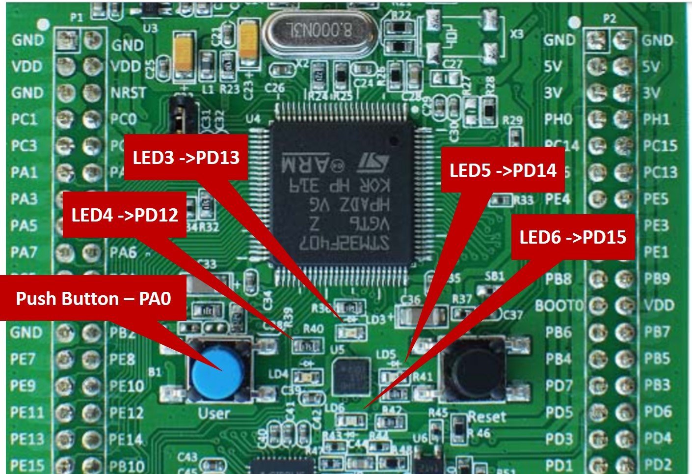
In the previous tutorial we learned how to control these four LEDs by configuring PD12–PD15 of PORTD as digital output pins. If you have not read that tutorial yet, start here:
STM32F4 Push Button Code
In this series of STM32F4 Discovery Board tutorials we use Keil uvision IDE and the STM32 HAL GPIO driver from STMicroelectronics. Make sure Keil MDK-ARM is installed and the STM32F4 device pack is already added before you run this code.
Complete Push Button Program
The program below controls the onboard LEDs of the STM32F4 Discovery Board using the onboard push button. When you press and hold the button, all four LEDs (green, orange, red, and blue) turn on. As soon as you release the button, the LEDs turn off. This is a minimal but complete example of using STM32F4 GPIO pins simultaneously as digital output (LEDs on PORTD) and digital input (button on PA0).
/* Code to control onboard LEDs of STM32F4 discovery board with onboard push button */
/* Include header file of STM32F4 series microcontroller */
#include "stm32f4xx_hal.h"

/* Function protoypes to configure GPIO pins as digital output and digital input */
void Init_OnBoard_LEDs(void);
void configure_Button(void);
void Delay_ms(volatile int time_ms); //ms delay function

/* main code to call initialize functions, read state of push button and controlling LEDs */
int main(void)
{
Init_OnBoard_LEDs(); // calls LEDs GPIO pins initialization function
configure_Button(); // call Push button GPIO pins initialization function
GPIO_PinState state; // Define a enum struct which contain boolean states
   while(1)
   {

state = HAL_GPIO_ReadPin(GPIOA, GPIO_PIN_0); // read state of push button and save it in "state" variable
 // if state is high, turn on  LEDs
    if(state)
	{
HAL_GPIO_WritePin(GPIOD, GPIO_PIN_12|GPIO_PIN_13|GPIO_PIN_14|GPIO_PIN_15, GPIO_PIN_SET);
	}
// if state is low, turn off LEDs
    else
       {
HAL_GPIO_WritePin(GPIOD, GPIO_PIN_12|GPIO_PIN_13|GPIO_PIN_14|GPIO_PIN_15, GPIO_PIN_RESET);
       }
   }
}

/* Function to configure PD12-PD15 pin of as digital output pins */
void Init_OnBoard_LEDs(void)
{
	 __HAL_RCC_GPIOD_CLK_ENABLE(); //Enable clock to GPIOD
	GPIO_InitTypeDef BoardLEDs; // declare a variable of type struct GPIO_InitTypeDef
	BoardLEDs.Mode = GPIO_MODE_OUTPUT_PP; // set pin mode to output
	BoardLEDs.Pin = GPIO_PIN_12|GPIO_PIN_13|GPIO_PIN_14|GPIO_PIN_15; // select pins PD12-PD15
	HAL_GPIO_Init(GPIOD, &BoardLEDs); // initialize PD12-PD15 pins by passing port name and address of BoardLEDs struct
}

/* Function to configure PA0 pin of as adigital input pin */
void configure_Button(void)
{
	__HAL_RCC_GPIOA_CLK_ENABLE(); //Enable clock to GPIOA
	GPIO_InitTypeDef PushButton;  // declare a variable of type struct GPIO_InitTypeDef
	PushButton.Mode = GPIO_MODE_INPUT; // set pin mode to input
	PushButton.Pin = GPIO_PIN_0;  // select pin PA0 only
	PushButton.Pull = GPIO_NOPULL; // set no internal pull-up or pull-down resistor
	HAL_GPIO_Init(GPIOA, &PushButton); //  initialize PA0 pins by passing port name and address of PushButton struct
}

/* ms delay function */
void Delay_ms(volatile int time_ms)
{
	      int j;
        for(j = 0; j < time_ms*4000; j++)
            {}  /* excute NOP for 1ms */
}
Build this project in Keil uvision (F7), flash it to the Discovery Board using the onboard ST-LINK (F8), and press the blue user button. All four LEDs will turn on for as long as you hold the button, and turn off the instant you release it.
How the STM32F4 Push Button Code Works
The LED initialization code comes directly from our previous STM32F4 LED blinking tutorial — we enable the clock to GPIOD, configure PD12–PD15 as push-pull digital outputs, and call HAL_GPIO_Init(). Nothing new there.
The new part is configure_Button(), which configures PA0 of PORTA as a digital input pin. After that, inside the while(1) loop, we continuously read the state of PA0 and drive the four LEDs accordingly.
Configure GPIO Pins as Digital Input Pins
The first step is to enable the peripheral clock for the GPIO port you are using. Without this line, writes to the GPIOA registers are silently ignored — exactly the same gotcha as the LED blinking tutorial.
__HAL_RCC_GPIOA_CLK_ENABLE(); //Enable clock to GPIOANext, declare a variable named PushButton of type GPIO_InitTypeDef. The same struct is used for both input and output pin configuration — only the Mode field changes.
GPIO_InitTypeDef PushButton; // declare a variable of type struct GPIO_InitTypeDefSet the pin mode to input using the Mode member of the PushButton struct.
PushButton.Mode = GPIO_MODE_INPUT; // set pin mode to inputThe Mode field accepts any of the following values from the HAL GPIO header. For simple push button reading, GPIO_MODE_INPUT is what you want. The GPIO_MODE_IT_* values would be used if you wanted the button to trigger an external interrupt instead of being polled in the main loop.
#define  GPIO_MODE_INPUT                        0x00000000U   /*!< Input Floating Mode                   */
#define  GPIO_MODE_OUTPUT_PP                    0x00000001U   /*!< Output Push Pull Mode                 */
#define  GPIO_MODE_OUTPUT_OD                    0x00000011U   /*!< Output Open Drain Mode                */
#define  GPIO_MODE_AF_PP                        0x00000002U   /*!< Alternate Function Push Pull Mode     */
#define  GPIO_MODE_AF_OD                        0x00000012U   /*!< Alternate Function Open Drain Mode    */

#define  GPIO_MODE_ANALOG                       0x00000003U   /*!< Analog Mode  */

#define  GPIO_MODE_IT_RISING                    0x10110000U   /*!< External Interrupt Mode with Rising edge trigger detection          */
#define  GPIO_MODE_IT_FALLING                   0x10210000U   /*!< External Interrupt Mode with Falling edge trigger detection         */
#define  GPIO_MODE_IT_RISING_FALLING            0x10310000U   /*!< External Interrupt Mode with Rising/Falling edge trigger detection  */

#define  GPIO_MODE_EVT_RISING                   0x10120000U   /*!< External Event Mode with Rising edge trigger detection               */
#define  GPIO_MODE_EVT_FALLING                  0x10220000U   /*!< External Event Mode with Falling edge trigger detection              */
#define  GPIO_MODE_EVT_RISING_FALLING           0x10320000U   /*!< External Event Mode with Rising/Falling edge trigger detection       */
Select PA0 of PORTA for the digital input function.
PushButton.Pin = GPIO_PIN_0; // select pin PA0 onlyDisable the internal pull-up and pull-down resistors, because the onboard user button on the STM32F4 Discovery Board already has an external pull-down resistor on the PCB.
PushButton.Pull = GPIO_NOPULL; // set no internal pull-up or pull-down resistorFinally, call HAL_GPIO_Init() with the port name (GPIOA) and the address of the PushButton struct. This writes all our settings into the GPIO configuration registers for PA0.
HAL_GPIO_Init(GPIOA, &PushButton); // initialize PA0 pin by passing port name and address of PushButton structHAL GPIO Pin Read Function
The second new HAL GPIO driver function used in this example is HAL_GPIO_ReadPin(). This routine reads the state of a specified input pin of a GPIO port and returns the state as a GPIO_PinState value — either GPIO_PIN_RESET (0) or GPIO_PIN_SET (1).
GPIO_PinState HAL_GPIO_ReadPin(GPIO_TypeDef* GPIOx, uint16_t GPIO_Pin)The first argument is a GPIO port (GPIOA, GPIOB, … GPIOI) and the second argument is the pin number of that port. The return value is a GPIO_PinState enum:
/**
  * @brief  GPIO Bit SET and Bit RESET enumeration
  */
typedef enum
{
  GPIO_PIN_RESET = 0,
  GPIO_PIN_SET
}GPIO_PinState;
/**
Inside main(), we first call Init_OnBoard_LEDs() and configure_Button() to initialize the GPIO pins:
Init_OnBoard_LEDs(); // calls LEDs GPIO pins initialization function
configure_Button(); // call Push button GPIO pins initialization function
Then we declare a variable of type GPIO_PinState to hold the state we read from the button:
GPIO_PinState state; // Define a enum struct which contains boolean states Inside the infinite while(1) loop we continuously read PA0 using HAL_GPIO_ReadPin() and store the result in state:
state = HAL_GPIO_ReadPin(GPIOA, GPIO_PIN_0); // read state of push button and save it in "state" variable
If state is HIGH, the button is pressed — so we turn on all four LEDs by setting PD12–PD15 of PORTD:
if(state)
{
HAL_GPIO_WritePin(GPIOD, GPIO_PIN_12|GPIO_PIN_13|GPIO_PIN_14|GPIO_PIN_15, GPIO_PIN_SET);
}
If state is LOW, the button is released — so we turn off the LEDs by clearing PD12–PD15:
else
{
HAL_GPIO_WritePin(GPIOD, GPIO_PIN_12|GPIO_PIN_13|GPIO_PIN_14|GPIO_PIN_15, GPIO_PIN_RESET);
}
A Note on Push Button Debouncing
Every mechanical push button produces a short burst of rapid HIGH/LOW transitions at the moment of press and release, caused by the metal contacts physically bouncing against each other. This effect lasts roughly 5–20 ms and is known as switch bouncing. For the simple “LEDs on while button held” code above, bouncing is invisible to you — the main loop runs fast enough that a few microseconds of bounce do not produce a visible flicker.
But for code that toggles an LED on each button press, or counts button presses, you must debounce the input. The two standard techniques on STM32F4 are: (1) add a short software delay (for example HAL_Delay(20)) after detecting a press, or (2) use a hardware timer to sample the button state every 10 ms and only register a press after several consecutive stable samples. Debouncing will be covered in a later tutorial in this STM32F4 series.
Troubleshooting STM32F4 Push Button Issues
- LEDs stay on all the time. You forgot to wire a pull resistor on an external push button, so PA0 (or whatever pin you used) is floating and reads HIGH most of the time. Enable the internal pull-down with
PushButton.Pull = GPIO_PULLDOWN. - LEDs stay off no matter what. Either the GPIOA clock is not enabled (
__HAL_RCC_GPIOA_CLK_ENABLE()), or the GPIOD clock is not enabled for the LEDs, or the button wiring is reversed. - LEDs flicker randomly. Your external button has no pull resistor — the pin is floating. Add a 10 kΩ pull-down/pull-up or enable the internal pull through the HAL
Pullparameter. - Button works reversed (LEDs on when released, off when pressed). You are in the opposite wiring convention to the one the code expects. Flip the
if(state)andelsebranches, or change from external pull-down to external pull-up. - LED toggles multiple times per press. Switch bouncing — add a 20 ms debounce delay after reading a press, or implement a proper debounce routine.
Frequently Asked Questions
Which pin is the onboard push button connected to on the STM32F4 Discovery Board?
The blue user push button (B1) on the STM32F4 Discovery Board is connected to PA0 — pin 0 of PORTA on the STM32F407VGT6 microcontroller — through an external pull-down resistor. This means PA0 reads LOW when the button is released and HIGH when the button is pressed.
Do I need an external pull-up resistor for a push button on the STM32F4?
Not necessarily. The STM32F407VG has internal pull-up and pull-down resistors on every GPIO pin, which you can enable via GPIO_InitTypeDef.Pull with either GPIO_PULLUP or GPIO_PULLDOWN. For most simple push buttons, the internal pulls are enough. Use an external resistor only when you need a specific, well-defined resistance value, or when the internal pull’s ~40 kΩ range is not suitable for your application.
What is the difference between polling and interrupt-based push button reading?
Polling (what this tutorial uses) means the main loop repeatedly calls HAL_GPIO_ReadPin() to check the button state. It is simple but keeps the CPU busy. Interrupt-based reading uses the STM32’s EXTI (external interrupt) lines — the MCU only runs your button-handling code when the pin actually transitions. Interrupt-based reading is more efficient and is the right choice whenever the rest of your program has other work to do. Set Mode = GPIO_MODE_IT_RISING (or _FALLING) and register a callback in HAL_GPIO_EXTI_Callback() to try it.
Why does my STM32 push button trigger twice on one press?
Switch bouncing. The mechanical contacts inside the button produce multiple electrical transitions in the first few milliseconds after a press or release. Add a debounce delay (typically 20 ms) after detecting a press, or sample the pin over several milliseconds and only register a press when the state is stable.
Can I use the same push button code on STM32 Nucleo or STM32 Blue Pill?
Yes, with two changes. First, update the port and pin — for example the Nucleo-F446RE user button is on PC13, and the Blue Pill does not have an onboard user button, so you will need to wire your own. Second, remember that active-high vs active-low depends on the board’s pull resistor — the Blue Pill LED is active-low, for example. The HAL functions themselves (HAL_GPIO_ReadPin(), HAL_GPIO_Init(), GPIO_InitTypeDef) are identical across all STM32 families.
Conclusion
In this STM32F4 Discovery Board push button tutorial you learned how to configure a GPIO pin as a digital input, how pull-up and pull-down resistors shape the idle state of that input, how the onboard user button on PA0 is wired to the STM32F407VGT6, and how to read its state with HAL_GPIO_ReadPin(). Combined with the LED output techniques from the previous tutorial, you now have the two fundamental building blocks for every embedded project: reading external signals and driving external devices. Next in the series we will use these GPIO skills together with the STM32F4’s onboard ADC to read analog signals.
Related Push Button and GPIO Tutorials
- LED Blinking Tutorial STM32F4 Discovery Board – GPIO Pins with HAL Library
- ADC STM32F4 Discovery Board with HAL ADC Driver – Polling Method
- Use Push Button to Control LED with TM4C123G Tiva LaunchPad
- Push Button with ESP32 – GPIO pins as digital input
- How to use push button with ATMEGA32 AVR microcontroller
- How to use push button with Arduino UNO R3