Interrupt processing in ARM Cortex-M microcontrollers is a critical aspect of how these devices manage real-time tasks efficiently. In this tutorial, we will discuss the sequences of steps that are performed by ARM Cortex M processor during interrupt processing. In other words, how ARM Cortex-M microcontroller handles interrupt or exceptions.
Recommended Components
The following components are used in this project or are helpful for getting started with TM4C123 Tiva C LaunchPad development.
| Component | How it’s used in this project | Buy on Amazon |
|---|---|---|
| TM4C123G Tiva C LaunchPad | ARM Cortex-M4 board whose interrupt processing is explained | Check Price |
| Micro USB Cable | Programs and powers the board from your computer | Check Price |
As an Amazon Associate we earn from qualifying purchases. Prices and availability are accurate as of the date/time indicated and are subject to change.
Types of Interrupt and Exceptions in ARM Cortex-M
Throughout this tutorial, we will use exception and interrupt terms interchangeably. Because, in ARM Cortex-M literature both terms are used to refer to interrupts and exceptions. Although there is a minor difference between interrupt and exception. Interrupts are special types of exceptions which are caused by peripherals or external interrupts such as Timers, GPIO, UART, I2C, etc, On the contrary, exceptions are generated by processor or system. For example, In ARM Cortex-M4, the exceptions numbered from 0-15 are known as system exceptions and the peripheral interrupts can be between 1 to 240. But the available number of peripheral interrupts can be different for different ARM chip manufacturers. For instance, ARM Cortex-M4 based TM4C123 microcontroller supports 16 system exceptions and 78 peripheral interrupts.
What Happens when Interrupt Occurs?
But whenever an exception or interrupt occurs, the processor uses an interrupt service routine for interrupts and an exception handler for system exceptions. In other words, whenever an interrupt occurs from a particular source, the processor executes a corresponding piece of code (function) or interrupt service routine.
Interrupt Vector Table and Interrupt Processing
But the question is how does the processor find the addresses of these interrupt service routines or exception handlers? In order to understand this, let’s take a review of the memory map of ARM cortex M4 microcontrollers. The address space which ARM MCU supports is 4GB. This memory map is divided into different memory sections such as code, RAM, peripheral, external memory, system memory region as shown in the figure below:
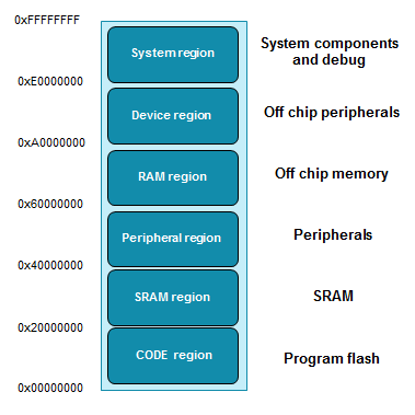
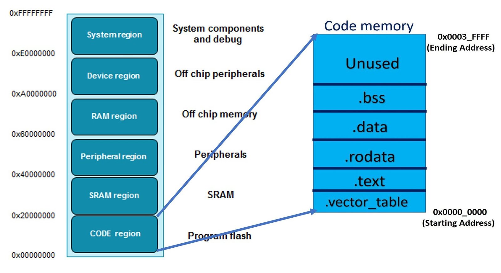
The flash or code memory region is used to store the microcontroller’s application code and it is further divided into different segments such as vector table, text, read-only data, read-write data, and bss segments. These sections are used for predefined functions.
If you want to explore more about these memory segments, we recommend you to read these tutorials:
Relocating ISR Address from IVT
Coming back to the main discussion, the code memory region contains an interrupt vector table (IVT). This interrupt vectors table consists of a reset address of stack pointer and starting addresses of all exception handlers. In other words, it contains the starting address that points to respective interrupt and exception routines such as reset handler. Hence, the microcontroller uses this starting address to find the code of the interrupt service routine that needs to be executed in response to a particular interrupt.
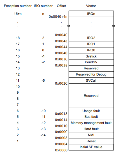
The figure below shows the interrupt vector table of the ARM Cortex-M4 microcontroller. As you can see, the interrupt vector table is an array of memory addresses. It contains the starting address of all exception handlers. Furthermore, each interrupt/exception also has a unique interrupt number assigned to it. The microcontroller uses interrupt number to find the entry inside the interrupt vector table. The following table shows the interrupt vector table of ARM Cortex M4 based TM4C123GH6PM microcontroller.
Examples
For example, when an interrupt x occurs, the nested vectored interrupt controller uses this interrupt number to find the memory address of the interrupt service routine inside the IVT. After finding the starting address of the exception handler, NVIC sends the request to the ARM microcontroller to start executing the interrupt service routine.
Lets take an example, let’s suppose, interrupt number 2 occures. The NVIC used this formula to find the entry of crossponding IRQx in IVT:
Entry in IVT = 64 +4 * x ;
for x=2
Entry in IVT = 64 +4 * 2 = 72
                      = 72 or 0x0048
As you can see from the above interrupt vector table, the address of IRQ2 is 0X0048. NVIC will get the starting address of IRQ2 from the memory location 0x0048 and sets the program counter to the starting address of IRQ2. After that processor jumps to this locations to execute ISR.
One important point to note here is that the value of the interrupt number is negative also. The interrupt number or IRQn of all system exceptions is in negative. This example shows the relocation of entry in IVT when bus fault exception occurs:
Entry in IVT = 64 +4 * x ;
For bus fault exception x = -11
Entry in IVT = 64 +4 * -11= 20
= 20 or 0x0014
Steps Executed by ARM Cortex M processor During Interrupt Processing
Till now we have discussed how ARM microcontroller finds the address of the first instruction of corresponding interrupt service routine. In this section, we will discuss we will see the sequence of steps that occurs during interrupt processing such as context switching, context saving, registers stacking and unstacking.
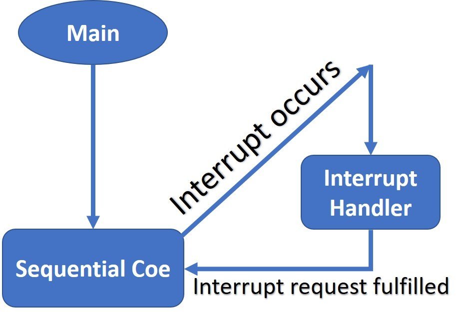
Whenever an interrupt occurs, the context switch happens. That means the processor moves from thread mode to the handler mode. As shown in this figure below, the ARM Cortex-M microcontroller keeps executing the main application but when an interrupt occurs, the processor switches to interrupt service routine. After executing ISR, it switches back to the main application again. But what happens during context switching requires more explanation.
For example, the ARM cortex-M processor executing these instruction inside the main code:
1. LDR R2 [R0]   // load value at address [R0] in register R2
2. LDR R1 [R0+4] // load value at address [R0+4] in register R1
3. ADD R3 R2 R1 // add R2+R1 and save the content in R3
4. STR R3 [R0] // Store R3 at address [R0]
The main application is executing the above instructions and the program counter is pointing to instruction 3. At the same time, an interrupt signal arrives.
ARM Cortex-M Context Switching
When an interrupt occurs and its request is approved by the NVIC and processor to execute, the contents of the CPU register are saved onto the stack. This way of CPU register preservation helps microcontrollers to start execution of the main application form the same instruction where it is suspended due to an interrupt service routine. The process of saving the main application registers content onto the stack is known as context switching.
But it takes time for the microcontroller to save the CPU register’s content onto the stack. But to Harvard architecture of ARM processors (separate instruction and data buses), the processor performs context saving and fetching of starting address of interrupt service routine in parallel.
Interrupts Processing Steps
The microcontroller will perform the following steps:
Stacking
- First ARM Cortex-M finishes or terminates currently under execution like the instruction number 3 (ADD R3 R2 R1 ) in the above example. The condition of finishing or terminating current instruction depends on the value of the interrupt continuable instruction (ICI) field in the xPSR register.
- After that suspend the current main application and save the context of the main application code into the stack. Microcontroller pushes registers R0, R1, R2, R3, R12, LR, Program counter and program status register (PSR) onto the stack.
The order in which stacking take place is PSR, PC, LR, R12, R3, R2, R1 and R0 and also shown in the figure below:

The new stack pointer will point to 32 bytes above the previous stack pointer position. Because we pushed 8 registers into the stack and each register is 4 bytes long.
Note: ARM Cortex-M microcontroller performs the interrupt vector fetching process in parallel to registers stacking process to improve interrupt latency.
Why are other registers (R4-R11) not pushed onto the Stack?
This reason is very simple. The interrupt service routines or exception handlers in ARM Cortex-M4 microcontrollers do not use R4-R11 registers during ISR execution. Hence, the content of these registers does not change. Only the content of PSR, PC, LR, R12, R3, R2, R1, and R0 changes. Therefore, the content of these registers is saved onto the stack.
Note: If the floating-point processor of FPU is also used, then the content of FPU registers also saves on stack.
Exception Entry
- After that, the ARM processor reads the interrupt number from the xPSR register. By using this interrupt number processor finds the entry of the exception handler in the interrupt vector table. Finally, it reads the starting address of the exception handler from the respective entry of IVT.
- Now ARM processor updates the values of the stack pointer, linker register (LR), PC (program counter) with new values according to the interrupt service routine. The link register contains the type of interrupt return address.
- After that interrupt services routine starts to execute and finish its execution.
Exception Return
The last step is to return to the main application code or to exist from the interrupt service routine. To return from ISR, the processor loads the link register (LR) with a special value. The most significant 24-bits of this value are set to 0xFFFFFF and the least significant eight bits provide different ways to return from exception mode. For example, if the least significant 8-bits are F9. The processor will return from exception mode by popping all eight registers from the stack. Also, it will return to thread mode using MSP as its stack pointer value.
Least significant 8-bits of the value which is loaded to LR register during the exception return process determine which mode to return either remain in exception mode ( in case of nested interrupts) or handler mode.
After that microcontroller starts to execute the main application from the same instruction where it is pre-empted by interrupt service routine.
Tail-Chaining and Late-Arriving Interrupts
- Tail-Chaining: If multiple interrupts occur in quick succession, the processor can handle them more efficiently by skipping some of the context-saving and restoring steps.
- Late-Arriving Interrupts: If a higher priority interrupt arrives while the processor is handling a lower priority one, it can immediately switch to the higher priority interrupt without completing the lower priority ISR.
Other ARM Cortex-M Interrupt Related Examples: