In this tutorial, we will discuss how to use GPIO interrupts which are also known as external interrupts of ARM Cortex M4 based TM4C123 microcontroller using the Tiva C launchpad. We will learn to configure GPIO interrupts as an edge triggered such as positive or negative edge or level triggered such as active high or active low level triggered. We will program the TM4C123G Tiva C launchpad with Keil uvision IDE. They are useful to make your program event-driven instead of polling for the resources.
Pre-requisites:
- How to Download and Install Keil uVision for ARM and 8051
- Getting started with Keil uVision: Write your first Program for Tiva LaunchPad
Recommended Components
The following components are used in this project or are helpful for getting started with TM4C123 Tiva C LaunchPad development.
| Component | How it’s used in this project | Buy on Amazon |
|---|---|---|
| TM4C123G Tiva C LaunchPad | Uses onboard SW1/SW2 and green LED for GPIO interrupts | Check Price |
| Micro USB Cable | Programs and powers the board from your computer | Check Price |
As an Amazon Associate we earn from qualifying purchases. Prices and availability are accurate as of the date/time indicated and are subject to change.
GPIO Interrupts Introduction
General-purpose input-output pins are the vital components of embedded systems. GPIO pins allow easy integration of external components with microcontrollers. Input pins allow microcontrollers to receive information from the external world and output pins are used to display information or control devices such as motors, etc.
Why do we need to use TM4C123 GPIO Interrupts ?
In the last tutorial on controlling an LED with push button using TM4C123 Tiva C launchpad, we have seen an example to control an onboard LED of Tiva Launchpad using onboard switches such as SW1 (PF0) and SW2 (PF4). In that tutorial, the TM4C123 microcontroller keeps checking the status of the push button by polling PF0 and PF4 bits of PORTF of TM4C123G microcontroller. But one of the main drawbacks of the polling method is that microcontroller will have to check the status of input switches on every sequential execution of the code or keep monitoring continuously (Polling method). Therefore, external or GPIO interrupts are used to synchronize external physical devices with microcontrollers.
Hence, instead of checking the status of input switches continuously, a GPIO pin which is configured as digital input, can be initialized to produce an interrupt whenever the state of the switch changes. A source of interrupt trigger can be on falling edges, rising edges or both falling and rising edges, level triggered also.
In summary, use of external GPIO interrupts makes embedded system event driven, responsive and they make use of microcontroller’s processing time and resources efficiently.
TM4C123GH6PM Microcontroller GPIO Interrupts
TM4C123GH6PM microcontroller has 6 GPIO ports such as PORTA, PORTB, PORTC, PORD, PORTE, and PORTF. Each pin of every GPIO port can be configured as a source of external interrupt. In this tutorial, we will see how to configure PF0 and PF4 pins as an external interrupt source. But the procedure to configure other GPIO interrupts will remain the same.
TM4C123 Tiva C Launchpad has two onboard switches SW1 and SW2 which are connected with PF0 and PF4 GPIO pins. These input switches will be used to demonstrate GPIO interrupt programming examples.

How to Configure External Interrupts of TM4C123
In this section, we will learn to configure TM4C123 microcontroller GPIO interrupts using their respective configuration registers.
Find GPO Interrupt Number
TM4C123 microcontroller has an integrated Nested Vectored Interrupt Controller (NVIC) which manages all interrupt requests which are issued either by a processor (exceptions) or peripherals(IRQs). TM4C123GH6PM microcontroller supports 76 peripheral interrupts (some are reserved) and each interrupt has a unique number assigned to it. This interrupt number is defined inside the startup file and header file of TM4C123GH6PM.
NVIC identifies each exception or peripheral interrupt by its numbers. If you see table 2.9 in the datasheet of TM4C123GH6PM MCU, you will find the unique number assigned to each exception and peripheral interrupt. As you can see in the second column of figure shown below, the interrupt number of GPIO PORTF is 30.
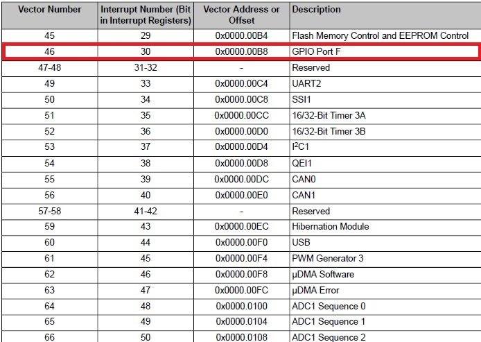
But one important thing to note here is that PORTF has 8 pins and only one interrupt number is assigned to all the pins of PORTF. This is because the separate interrupt register is used to distinguish which pin of PORTF caused the interrupt. We will discuss it later on in this article.
Enable GPIO Interrupts
Before enabling any peripheral interrupt, we must enable the source of interrupt requests for this particular interrupt source using the NVIC interrupt control register. In the interrupt vector table, there is an interrupt enable bit number for each interrupt source. We can enable these interrupt bits using NVIC interrupt enable registers. There are four NVIC interrupts enable registers such as EN0(ISER[0]), EN1(ISER[1]), EN2(ISER[2]) and EN3(ISER[3]).
The ENn(ISER[n])registers enable interrupts and shows which interrupts are enabled. Bit0 of EN0 corresponds to Interrupt 0; bit31 corresponds to Interrupt 31. Bit 0 of EN1(ISER[1])corresponds to Interrupt 32; bit31 corresponds to Interrupt 63 and so on other two registers.
For example, the interrupt number of PORTF is IRQ30. Hence the corresponding NVIC interrupt enable register of PORTF is ISER[0] and setting bit 30 of ISER[0] will enable the PORTF interrupt.
NVIC->ISER[0] |= (1<<30); /*Enable PORTF Interrupt IRQ30 */After enabling interrupt in NVIC register, enable the interrupt of the peripheral which you want to use. For example, we will be using GPIOF pins interrupt. In order to enable GPIO interrupt GPIO interrupt mask enable register is used. First eight bits of GPIOIM register enable or disable interrupt functionality for each pin as shown in figure below:
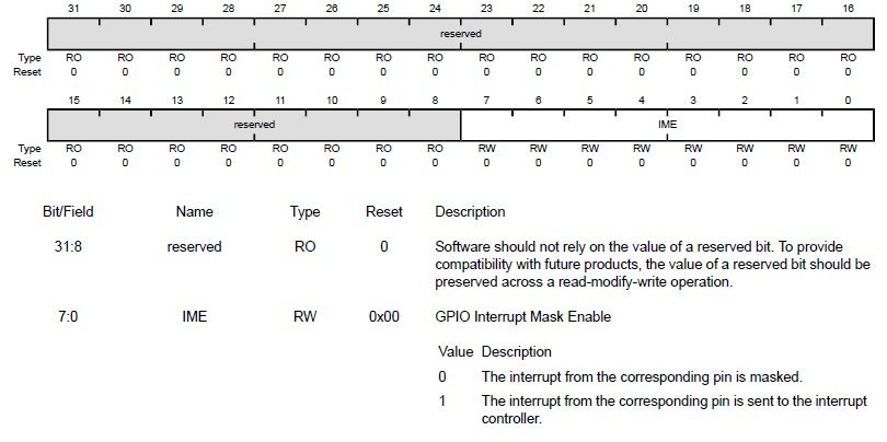
For example, we will use PF0 and PF4 pins of PORTF to get SW1 and SW2 status on interrupt. This line enables interrupt for PF0 and PF4 pins.
GPIOF->IM |= (1<<4)|(1<<0);GPIO Interrupt edge or level triggered setting (GPIOIS)
As we mentioned earlier, external GPIO interrupts of TM4C123G microcontroller can be configured in four modes:
- Positive edge triggered
- Negative edge triggered
- Positive Level ( active high)
- Negative Level (active low)
GPIO interrupt sense register is used to configure respective pins either as a level or edge triggered. Setting a bit in the GPIOIS register configures the corresponding pin to detect levels while clearing a bit configures the corresponding pin to detect edges.
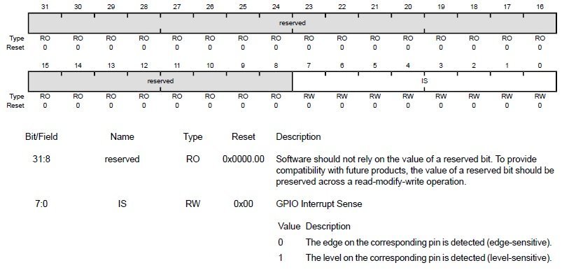
For example, this line initializes the PF0 and PF4 pins as edge triggers.
GPIOF->IS &= ~(1<<4)|~(1<<0); /* make bit 4, 0 edge sensitive */Similarly, this line initializes the PF0 and PF4 pins as level triggers
GPIOF->IS |= (1<<4)|(1<<0); /* make bit 4, 0 level sensitive */GPIO Interrupt Even Register (GPIOIEV)
GPIOIS register only configures the pins as level or edge triggered. But we should also configure the pin either as a positive/negative edge or positive/negative level triggered. Setting the respective bit in GPIOIEV register configures the corresponding pin to detect positive edge or positive level depending on in which mode pin is configured in GPIOIS register. Similarly, Clearing the respective bit in GPIOIEV register configures the corresponding pin to detect negative edge or negative level.

GPIOF->IEV &= ~(1<<4)|~(1<<0); /*PF0, PF4 falling edge trigger */GPIO Interrupt Both Edges (GPIOIBE)
We can also configure GPIO pins to cause interrupt on both positive or negative edges. GPIOIBE register is used to configure each pin to cause an interrupt on both edges. setting a bit in the GPIOIBE register configures the corresponding pin to detect both rising and falling edges, regardless of the corresponding bit in the GPIO Interrupt Event (GPIOIEV) register (see page 666). Clearing a bit configures the pin to be controlled by the GPIOIEV register.
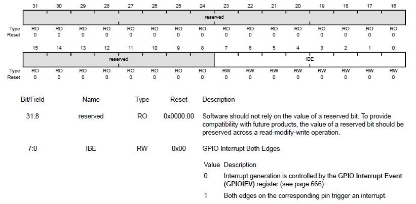
These lines configure the PF0 and PF4 pins to detect positive edges.
GPIOF->IS  &= ~(1<<4)|~(1<<0); /* make bit 4, 0 edge sensitive */
GPIOF->IBE &=~(1<<4)|~(1<<0);  /* trigger is controlled by IEV */
GPIOF->IEV &= ~(1<<4)|~(1<<0);   /* falling edge trigger */
GPIO Interrupt Handler Name
In the startup file of TM4C123G microcontroller, there is a vectored mapped table which contains the starting addresses of all system exceptions and peripheral interrupt service routines. This file also contains the dummy implementations of exception Handlers or interrupt Handlers. These dummy implementations do nothing except an infinite loop and we can modify these dummy interrupt handlers inside our main code.
So in order to implement specific functionality inside the respective interrupt handler function, we should find the name of the corresponding peripheral interrupt in the startup file. For example, if you open the startup file of TM4C123 and explore it, you will find that the name of PORTF interrupt handler is GPIOF_Handler. Inside our main code, we will use GPIOF_Handler as a function name for GPIOF interrupt service routine.

The linker script file will automatically replace the dummy implementation of GPIOF_Handler inside the startup file with our defined implementation.
TM4C123 Tiva C GPIO Interrupt Example
For demonstration purposes, in this example, we will configure PF0 and PF1 pins to cause interrupts on negative edges. On TM4C123 Tiva C Launchpad, there are two onboard switches such as SW1 and SW2. SW1 is connected with the PF4 pin and SW2 is connected with PF0 pin as shown in figure below.
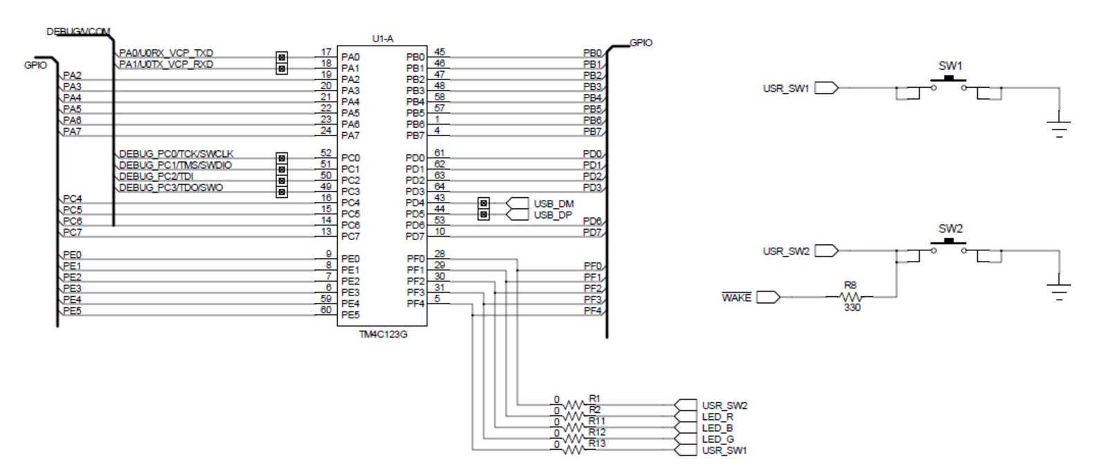
One end of both input switches are connected with ground and the other end with PF0 and PF4 pins. TM4C123GH6PM microcontroller provides internal pull-up resistors which can be configured using GPIOPUR register. This line enables the pull-up resistor for PF4 and PF0 pin.
GPIOF->PUR |= (1<<4)|(1<<0); /* enable pull up for PORTF4, 0 */By enabling pull-up resistors, active high signals will appear on PRF4 and PF0 pins when switches are not pressed. But when we press the switch button, the transition of the signal occurs from active high to active low that means a negative edge will occur. We will configure PF0 and PF4 pins to detect negative edges and cause an interrupt. Hence, whenever the user presses either of the push buttons, an interrupt will be generated and TM4C123 microcontroller executes the interrupt handler function of PORTF.
Inside the PORTF interrupt handler function, we will turn on the onboard green LED of TM4C123 Tiva C launchpad, if SW1 is pressed and turns off the LED if SW2 is pressed.
External Interrupt Code TM4C123 MCU
This code controls the green LED of the TM4C123 Tiva launchpad based on SW1 and SW2 states. Both switches are used to generate external interrupt signals on negative edges (falling edge). If the interrupt is caused by SW1(PF4) LED will turn on and if the interrupt is caused by SW2(PF0) LED will turn off.
/*PORTF PF0 and PF4 fall edge interrupt example*/
/*This GPIO interrupt example code controls green LED with switches SW1 and SW2 external interrupts */

#include "TM4C123.h"                    // Device header

int main(void)
{

	  SYSCTL->RCGCGPIO |= (1<<5);   /* Set bit5 of RCGCGPIO to enable clock to PORTF*/

	 /* PORTF0 has special function, need to unlock to modify */
    GPIOF->LOCK = 0x4C4F434B;   /* unlock commit register */
    GPIOF->CR = 0x01;           /* make PORTF0 configurable */
    GPIOF->LOCK = 0;            /* lock commit register */


    /*Initialize PF3 as a digital output, PF0 and PF4 as digital input pins */

    GPIOF->DIR &= ~(1<<4)|~(1<<0);  /* Set PF4 and PF0 as a digital input pins */
    GPIOF->DIR |= (1<<3);           /* Set PF3 as digital output to control green LED */
    GPIOF->DEN |= (1<<4)|(1<<3)|(1<<0);             /* make PORTF4-0 digital pins */
    GPIOF->PUR |= (1<<4)|(1<<0);             /* enable pull up for PORTF4, 0 */

    /* configure PORTF4, 0 for falling edge trigger interrupt */
    GPIOF->IS  &= ~(1<<4)|~(1<<0);        /* make bit 4, 0 edge sensitive */
    GPIOF->IBE &=~(1<<4)|~(1<<0);         /* trigger is controlled by IEV */
    GPIOF->IEV &= ~(1<<4)|~(1<<0);        /* falling edge trigger */
    GPIOF->ICR |= (1<<4)|(1<<0);          /* clear any prior interrupt */
    GPIOF->IM  |= (1<<4)|(1<<0);          /* unmask interrupt */

    /* enable interrupt in NVIC and set priority to 3 */
    NVIC->IP[30] = 3 << 5;     /* set interrupt priority to 3 */
    NVIC->ISER[0] |= (1<<30);  /* enable IRQ30 (D30 of ISER[0]) */


    while(1)
    {
			// do nothing and wait for the interrupt to occur
    }
}

/* SW1 is connected to PF4 pin, SW2 is connected to PF0. */
/* Both of them trigger PORTF falling edge interrupt */
void GPIOF_Handler(void)
{
  if (GPIOF->MIS & 0x10) /* check if interrupt causes by PF4/SW1*/
    {
      GPIOF->DATA |= (1<<3);
      GPIOF->ICR |= 0x10; /* clear the interrupt flag */
     }
    else if (GPIOF->MIS & 0x01) /* check if interrupt causes by PF0/SW2 */
    {
     GPIOF->DATA &= ~0x08;
     GPIOF->ICR |= 0x01; /* clear the interrupt flag */
    }
}
How Code Works?
This code configures and handles GPIO interrupts on a TM4C123 microcontroller (part of the Texas Instruments Tiva C series). The code sets up interrupts for switches connected to pins PF0 and PF4 of PORTF. The interrupt is triggered when these pins detect a falling edge (i.e., when the switch is pressed). Based on which switch is pressed, it controls the green LED connected to pin PF3.
Clock and Unlocking
   SYSCTL->RCGCGPIO |= (1<<5);   /* Set bit 5 of RCGCGPIO to enable clock to PORTF */
   GPIOF->LOCK = 0x4C4F434B;     /* Unlock commit register to configure PF0 */
   GPIOF->CR = 0x01;             /* Make PORTF0 configurable */
GPIOF->LOCK = 0; /* Lock commit register after configuration */- The clock for PORTF is enabled by setting bit 5 in
RCGCGPIO. - PF0 is a special pin that needs to be unlocked before it can be configured. The unlock sequence is achieved by writing a specific key (
0x4C4F434B) to theLOCKregister, allowing changes to be made to the commit register (CR). After configuring, the lock is re-enabled.
GPIO Configuration
   GPIOF->DIR &= ~(1<<4)|~(1<<0);  /* Set PF4 and PF0 as digital input pins */
   GPIOF->DIR |= (1<<3);           /* Set PF3 as digital output to control green LED */
   GPIOF->DEN |= (1<<4)|(1<<3)|(1<<0); /* Enable digital function on PF4, PF3, and PF0 */
GPIOF->PUR |= (1<<4)|(1<<0); /* Enable pull-up resistors on PF4 and PF0 */- PF4 and PF0 are configured as input pins (connected to switches SW1 and SW2).
- PF3 is configured as an output pin to control the green LED.
- Digital functions are enabled for the configured pins using the
DENregister. - Pull-up resistors are enabled on PF4 and PF0 to ensure a defined logic level when the switches are not pressed.
Interrupt Configuration
   GPIOF->IS  &= ~(1<<4)|~(1<<0);  /* Set PF4 and PF0 as edge-sensitive */
   GPIOF->IBE &= ~(1<<4)|~(1<<0);  /* Trigger controlled by IEV */
   GPIOF->IEV &= ~(1<<4)|~(1<<0);  /* Falling edge trigger */
   GPIOF->ICR |= (1<<4)|(1<<0);    /* Clear any prior interrupts */
GPIOF->IM |= (1<<4)|(1<<0); /* Unmask interrupts for PF4 and PF0 */- The pins PF4 and PF0 are set to detect edge-triggered interrupts (rather than level-triggered).
- The interrupts are configured to trigger on the falling edge, which occurs when the switch is pressed.
- Any prior interrupt flags are cleared, and the interrupts are unmasked, meaning they are enabled.
NVIC Configuration
   NVIC->IP[30] = 3 << 5;     /* Set interrupt priority to 3 */
NVIC->ISER[0] |= (1<<30); /* Enable IRQ30 (corresponding to PORTF in NVIC) */- The interrupt priority is set to 3 (lower priority values have higher priority).
- The interrupt for PORTF (IRQ30) is enabled in the Nested Vectored Interrupt Controller (NVIC).
Main Loop
   while(1)
   {
       // do nothing and wait for the interrupt to occur
}- The main loop is empty, waiting for interrupts to occur. The program’s main functionality is interrupt-driven.
Interrupt Service Routine (ISR)
   void GPIOF_Handler(void)
   {
     if (GPIOF->MIS & 0x10) /* Check if interrupt was caused by PF4/SW1 */
     {
       GPIOF->DATA |= (1<<3);  /* Turn on green LED (set PF3) */
       GPIOF->ICR |= 0x10;     /* Clear the interrupt flag for PF4 */
     }
     else if (GPIOF->MIS & 0x01) /* Check if interrupt was caused by PF0/SW2 */
     {
       GPIOF->DATA &= ~0x08;  /* Turn off green LED (clear PF3) */
       GPIOF->ICR |= 0x01;    /* Clear the interrupt flag for PF0 */
     }
}- The
GPIOF_Handlerfunction is the ISR that handles interrupts from PORTF. - It checks which pin caused the interrupt by inspecting the Masked Interrupt Status (
MIS) register. - If the interrupt was caused by PF4 (SW1), the green LED is turned on (by setting PF3).
- If the interrupt was caused by PF0 (SW2), the green LED is turned off (by clearing PF3).
- The interrupt flag is cleared for the corresponding pin to acknowledge and clear the interrupt.
This code effectively controls an LED using external switches with the TM4C123 microcontroller, utilizing edge-triggered interrupts for responsiveness.
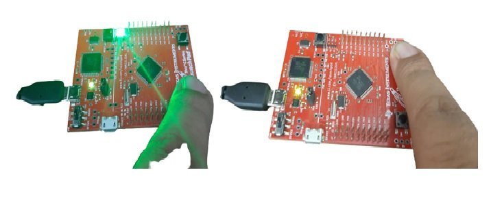
Now create a new project using Keil uvision and upload this code to TM4C123G Tiva C Launchpad. After that press the reset button of the launchpad. Finally, check the working of code, by pressing SW1 and SW2.
Differentiating which GPIO pin causes Interrupt
As we mentioned earlier, there is only one interrupt service routine for each GPIO port. For example, PORTF has one interrupt handler function that is GPIOF_Handler(). Interrupt caused by all the pins of PORTF executes the same GPIOF_Handler() interrupt service routine. Now the question is how to differentiate which of the pins of PORTF forces the GPIOF_Handler() function to execute?
Well that’s pretty easy, TM4C123GH6PM microcontroller has GPIO masked interrupt status register (GPIOMIS). This register provides the status of interrupt caused by each pin. The first eight bits of this register corresponds to the PIN0 to PIN7 of each GPIO interrupt status.
For example, if the interrupt service routine of PORTF is called due to PF0 pin, the 0th bit of GPIOMIS register will be one and if it is caused by PF4 pin, 4th bit of GPIOMIS register will set automatically. Hence, by checking the value of each bit of GPIOMIS register inside the PORTF interrupt handler function, we can identify which pin causes this particular interrupt.
In this code, we used GPIOMIS register to differentiate either PF0 or PF4 causing the external interrupt, and based on this, the code executes only the true condition block of if-else.
/* SW1 is connected to PF4 pin, SW2 is connected to PF0. */
/* Both of them trigger PORTF falling edge interrupt */
void GPIOF_Handler(void)
{
  if (GPIOF->MIS & 0x10) /* check if interrupt causes by PF4/SW1*/
    {
      GPIOF->DATA |= (1<<3);
      GPIOF->ICR |= 0x10; /* clear the interrupt flag */
		}
    else if (GPIOF->MIS & 0x01) /* check if interrupt causes by PF0/SW2 */
    {
     GPIOF->DATA &= ~0x08;
     GPIOF->ICR |= 0x01; /* clear the interrupt flag */
    }
}
Other TM4C123 MCU Interrupt Tutorials
The best I ever read about “interrupt”
How did you find the MIS values for the switches?
I have problem working on this code, are you sure this code is working correctly in Keil Vision-4.
You can try with Keil uvision 5 and for us, it works with both v4 and v5.
It works Keil uvision v5 correctly, but it gives such an error for Keil uvision v4
“main.c(13): error: #137: expression must be a modifiable lvalue
GPIOF->CR = 0x01; /* make PORTF0 configurable */”
Do you have any suugestions why I get this error?
Hi, Potter,
We recommend you to use Keil vision v5 because the register definition file for TM4C123 has issues in V4. But in Keil vision v5, there are some missing definitions in the startup file. Therefore, we will soon provide the updated startup file for v5 with the that you will be able to follow all tutorials with Keil vision v5.
Thanks
Replace the content of startup file available in your project with the content file available on this link:
https://raw.githubusercontent.com/bilalmalik76/startupfile-TM4C123-V5/main/startup.s
Thank you for reply.
I am beginner in ARM world with this Tiva C. I ran this code, but there is nothing. No reaction to the buttons and LED. I use Keil uVision 5. What is the problem here?