In the last tutorial, we have seen how to download and install Keil uVision. In this tutorial, we will see how to create your first project using Keil according to microcontroller you want to use. After that, we will explain how to write your first program in Keil uVision.
Introduction to keil uVision
As we have discussed in previous tutorial that keil uVision is an IDE used to build and load codes on TIVA C series microcontroller. In the previous tutorial we learned how to download and install the latest version of keil uVision and now we are at a position to learn how to write our first program in keil which can be loaded on TIVA C series microcontroller. We will do the relevant settings in a simple program to make it compatible with the microcontroller under consideration so that we can burn (load) it on the board. Lets’ get started with keil (installed in previous tutorial).
Getting started with keil uVision
Once you get done with the downloading and installation part of Keil it will appear in you search bar.
Open Keil IDE
Open the search bar in your computer and type Keil and click on Keil uVision5 as shown in the figure below.
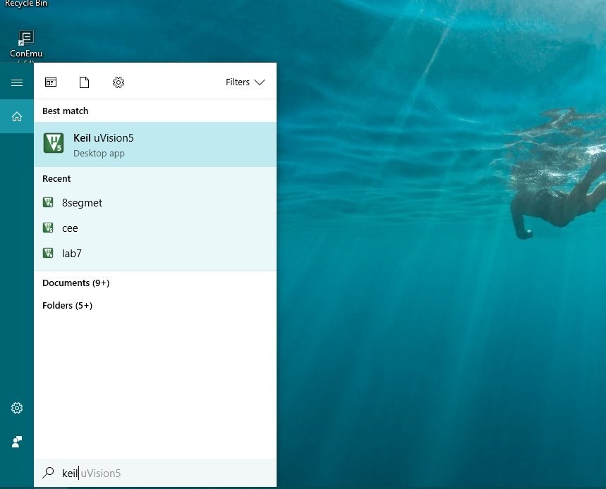
Once you click on this icon keil will start loading to show you the main window. It will take some time to open the page,

After the IDE is loaded completely a getting started window will appear as shown in the figure below:

Create New Project
This is where all your currently open projects will appear and your main code and all the codes you run will appear in the greyed window. To work on a program or a debugging environment we first have to create a project where will save our main and startup files. If will give you a brief and concise overview of the startup files in the upcoming tutorials, you don’t have to be worried about them at this point of your understandings.
Lets’ now move to create a new project portion. On the main page, as shown in the figure above, a bar is shown with file edit and view, etc. options in it. From that bar, select Project and then select New uVision Project as shown in the figure below,

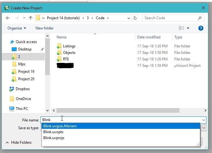
When you click on the New uVision Project a window will appear as shown in the figure below,
Select Tiva C series LaunchPad
This window will ask you where you want to save the project, select the designated folder and also name you project according to the working it is going to perform in future. I will use this project in the upcoming tutorial for the purpose of blinking of built in LEDs present n the F port of TIVA board.
Hence, I named the project as a blink (In accordance with the task it is going to perform). After naming the project click Ok. After saving the name another window asking you to select the device with which you want to integrate this code. This is where we select the name and type of our board. Refer to the figure below:

In this window two boards are present one is ARM and the other is Texas Instruments as is obvious from the above figure. TIVA C boards are manufactured by Texas Instruments hence the board we will select at this stage is Texas Instruments. When we extend this block all the downloaded board of Texas Instruments will appear as shown in the figure below,

As we know that TIVA c series is the only option available so we extend that too, as shown in the figure below,

At present only two classes of TIVA C series is installed, we can install more according to our need from pack installer as we have discussed in previous tutorials, but at present, we need TM4C123x Series because our microcontroller (TM4C123G) lies within this class. Extend TM4C123x Series to select the board of our choice from the series as shown in the figure below,
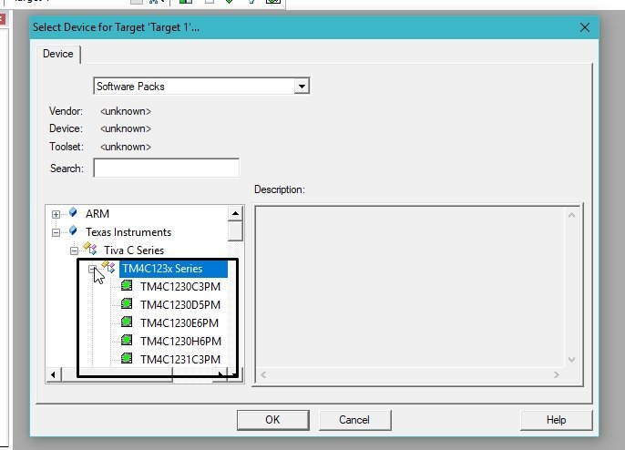
The microcontrollers present under this series are shown in the above figure. One thing to be noted down here is that the type of the microcontroller. we are using is TM4C123GXL but in this series you couldn’t find any board named like this. The alternative name for this board is TM4C123GH6PM this is the same as TM4C123GXL.
But with a different name only in the IDE. Remember this name of save it somewhere for future use, where we will be creating projects very often. See the figure below for the alternative name
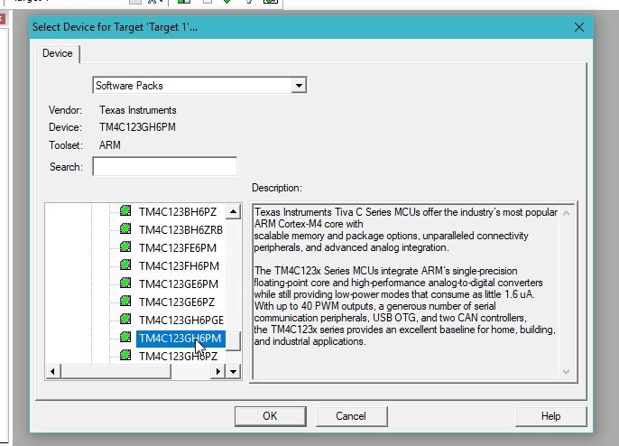
After you select the name of the microcontroller, simply click ok. The window will then ask you to choose the runtime environment of your choice. As I have mentioned previously that the startup files need to be included in every code so this is a portion where we will choose the inclusion of startup files. The window for managing runtime environment is shown in the figure below:

This window will select all the files which need to be included in your programming environment. For example, if you want to include graphics in your program you have to select it from here first. At this point, we only need to include two files one is the core file that is present under the category of CMSIS and the other is a startup file that is present under the category of Devices. Click on the plus sign present with the CMSIS category from the option given select CORE and mark the checkbox in front of CORE and do the same with the devices option. Extend the plus sign and mark the checkbox of a startup as shown in the figure below:

Project Settings
We will discuss comprehensively this startup file in the upcoming tutorials. After selecting the files click on Ok and the project will be created. The created project will appear on the project explorer on the left side of the main page. Right-click on target 1 and select Manage Project items as shown in the figure below,
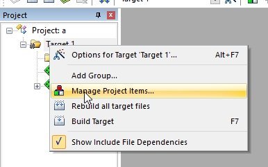
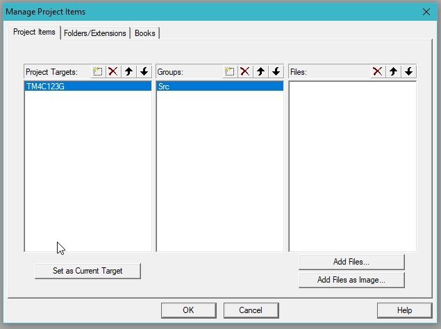
A window that manages the items of the project will appear as shown in the figure below,

- This is where you can rename all the folder and files of your project according to your need i.e. here I will name the target 1 as TM4C123G and Source Group 1 as Src because this is where all the source files of your code will reside as shown in the figure below,
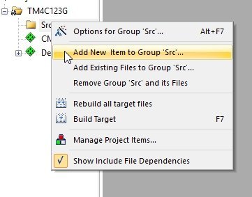
In the Src folder named previously we will include our main file (.c file) in which we will write our C language code to be executed on the board. On the Src folder click right and select Add new items to Group “Src” as shown in the figure below,
Keil Creating C file
Clicking on this adding item block a window will appear asking you to select the extension of your file and to write the name of your file as shown in the figure below. Select the C file (.c) option and in the name bar write the nae with which you want to save the file i.e. I named my file as main.c here. Don’t forget to type the extension of the file (.c in our case) along with the name of the file as shown in the figure below

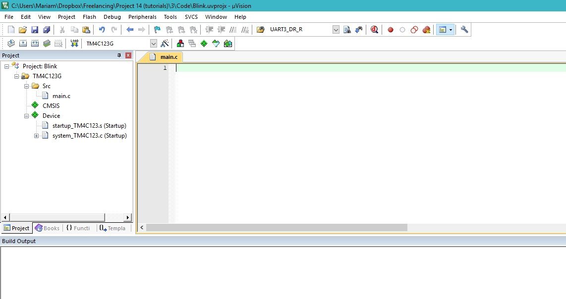
After you click add on this window, a main.c file will appear under the folder of Src. When you click on the main.c file it will open in the grey environment as shown in the figure below,
Keil Configuration Settings
The only thing left in the configuration of the project to make it compatible with TM4C123G board is its flash configuration. As the name represent flash is the configuration of the port from where TIVA board will be connected to your computer. Without the configuration of flash your will not be able to burn you code on the TIVA board. It will give you a flash error. In order to avoid this ambiguity lest configure some of the flash configuration needed to communicate with TIVA board. From the top bar select Flash and then select Configure flash tools as shown in the figure below,

This will open a window showing a number of tools related to flash that can be configured according to the type of our microcontroller and our need. Refer to the figure below, for flash configuration tools window,

You have nothing to change here because most of the default properties of the flash are compatible with TIVA C series boards, On the top bar a number of options are present. From these items select the Debug options as we are concerned with debugging configuration of flash. The debug configuration of the options is shown in the figure below,
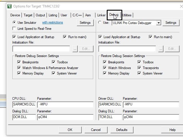
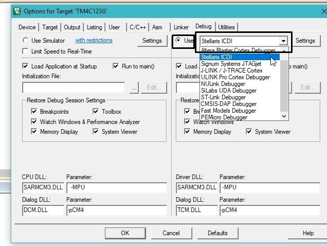
From this block we only have to change the simulator settings as shown in the figure below. Check the Use block present on the top right corner of the block and from the dropdown select Stellaris ICDI and then click ok. These are all the configurations needed to run a program on TM4C123G board.
Your IDE is now ready to write a code to be built on the TIVA board. We will write a code that will blink built-in LEDs present on TIVA board in our next tutorial.
In summary:
In conclusion, following the successful download and installation of Keil uVision in our previous tutorial, this session guided you through the process of creating your first project tailored to the microcontroller of your choice. We then demonstrated how to write your first program in Keil uVision, providing you with the foundational skills necessary to begin your journey in microcontroller programming. With these steps completed, you are now equipped to explore more advanced features and capabilities of Keil uVision in your future projects.
Other tutorials:
- Use Push Button to Control LED with TM4C123G Tiva LaunchPad
- Accessing Memory Mapped Peripherals Registers of Microcontrollers
- SysTick Timer (System Timer) TM4C123G ARM Cortex M4 Microcontroller
- Systick Timer Interrupt Programming TM4C123 ARM Cortex M4
- What is Interrupt Vector Table?
- Nested Vectored Interrupt Controller (NVIC) ARM Cortex-M Microcontrollers
Images to any TIVA series article is not visible.
Please fix it.
Thanks for pointing out. We will update the TIVA pinout image with high resolution
If Stellaris is not available, you can download it here: http://www.keil.com//files/download/MDK_Stellaris_ICDI_AddOn.exe
The MDK_Stellaris_ICDI_AddOn.exe being an exe-file not a DFP-file, when executing it, will it find the right directory and install itself in a way that it automaticly appears in the target->simulator checkbox?
No. I executed MDK_Stellaris_ICDI_AddOn.exe and reopend the target->debug, but no choice for Stellaris appeared.
So could someone please give me a a thorough explination of how to get a debugger that works with the Tiva C.series bord
This Error comes when try to run the project
Error: Flash Download failed – Could not load file ‘C:UsersamithDocumentsArmObjectsblink.axf’