In this tutorial, we will learn how to use general purpose input-output pins of TM4C123 as a digital input pins. For demo, we will see how to control and LED with on-board Push buttons of TM4C123G TIVA launchpad. Firstly, you should know how to use GPIO pins of TM4C123G6PM microcontroller as digital output pins. In the last tutorial, we have learned to use GPIO pins as digital output pins. If you did not use digital output pins of Tiva launchpad before, you should read this tutorial first:
How to use GPIO pins of TM4C123G Launchpad
Recommended Components
The following components are used in this project or are helpful for getting started with TM4C123 Tiva C LaunchPad development.
| Component | How it’s used in this project | Buy on Amazon |
|---|---|---|
| TM4C123G Tiva C LaunchPad | Uses its onboard push buttons and RGB LED on PORTF | Check Price |
| Micro USB Cable | Programs and powers the LaunchPad via onboard ICDI debugger | Check Price |
As an Amazon Associate we earn from qualifying purchases. Prices and availability are accurate as of the date/time indicated and are subject to change.
TM4C123G LaunchPad Push Button Interfacing
TM4C123G launchpad as onboard three LEDs such as green, blue, and read. Moreover, it also has two push buttons which are mentioned on the board as switch-one and switch-two. If you check the reference manual of this development, you will find that these onboard LEDs and switches have connections with POTF of TM4C123G6PM microcontroller.

As you can see in this picture, this ARM Cortex M4 microcontroller-based development board has two switches which are connected with PF0 and PF4 pins of TM4C123G6PM and a one RGB led interfaced with pins PF1, PF2 and PF3 of PORTF.

As you can also see from the schematic diagram given above, there is no pull-up resistor available with switch-one and switch-two. But the good thing is that the TM4C1235G series microcontroller has internal pull-up and pull-down registers associated with each port. We can configure these resistors using a respective GPIO port register. In the programming section, we will see how to configure this register.
How to use Switch as a digital Input
Mechanical switches are commonly used to feed any parameters to the digital systems. The switches can be interfaced to a microcontroller using digital inputs. The software program for switch interfacing can be implemented using one of the following methods.
- Polling based method
- Interrupt based method
We will discuss polling based switch interfacing in this tutorial. Before proceeding further, it is important to first make ourselves familiar with the physical behavior of switch and be will describe switch bouncing next, which is one of the critical attribute of its physical behavior.
Switch bouncing
Electrical switches that use mechanical contacts to close or open a circuit are subject to bouncing of the contacts. Switch inputs are asynchronous and are not electrically clean. When a hardware switch is pressed the mechanical contact of the switch that is made to complete the electrical connection will start bouncing. This bouncing effect will read a single press I in the software as multi presses of the switch.
The software will get confused whether about how many times the switch was pressed. Both software, as well as a hardware solution to this problem, are present. If we want to remove this problem using a hardware circuit, we will be using a simple RC filter. The values of the resistor and capacitor will be chosen such that the input will be captured after the bouncing period is over. The bouncing effect of a switch is shown in the figure below,

The above figure is the exact elaboration of the deb bouncing effect of the switch. At the start, the switch is at off (0) state. When the switch is activated it will result in multiple bouncing as is obvious from the figure, before actually coming to steady ON (1) state. The same is the case when the switch is deactivated. This issue may not cause any problem where you are working solely with hardware, but while working with the GPIO pins of the TIVA launchpad, one press will be interpreted as multiple presses and the results may not be in accordance with the desired or required results.
This is one of the most important points to be considered while working with switches. If we are interested in using the built-in switch of the board, we must configure the corresponding pin of the board as an input pin. The pin will read data from the switch and according to the data obtained from the switch it will control the built-in LED of the board which is configured as an output
Controlling an LED with a push button using Tiva Launchpad
Firstly, let’s see a simple example to control LED connected with PF1 pin using switch-one which is connected with the PF4 pin of PORTF. That means, whenever a user presses the push button that is connected with the PF0 pin of TM4C123G6PM microcontroller, LED will turn on. Moreover, as soon as the user releases the push button, the LED turns off.
| Pin | Function |
|---|---|
| PF1 | LED – Red |
| PF4 | On-Board Switch-2 |
GPIO pins as Digital Input Registers Configuration
In this tutorial, we will use registers definition header file available in Keil that contains TM4C123G6PM microcontroller general purpose and peripheral register definitions instead of creating our own register definition file.
In the last tutorial, we give you a general concept of how direct pointers dereferencing is used to update microcontroller peripherals registers values by using registers memory addresses. TM4C123G6PM.h header file contains a listing of all peripheral register’s memory addresses. Hence, we can use this header file instead of creating our own. But you should have an idea of how microcontroller peripheral registers are accessed through direct memory dereferencing via pointers.
Include Header File
Now let’s write a code to control red LED with switch-2 of tiva launchpad. First, include the header file of TM4C123GH6PM microcontroller like this:
#include "TM4C123GH6PM.h"After that, we initialize an unsigned integer variable with the name of “state”. It will be used to hold the state of the button.
unsigned int state;GPIO Pins Clock Enable Register
As we discussed in the previous tutorial, by default, the clock option is disabled for all GPIO ports of TM4C123GH6PM microcontroller to save power. But, we can enable the clock for each port using the RCGCGPIO register. Setting the 5th bit of the RCGCGPIO register enables the clock for PORTF.
Refer to page 340 of TM4C123GH6PM microcontroller datasheet for more information on this register.
SYSCTL->RCGCGPIO |= 0x20; // enable clock to GPIOFGPIO Lock and Commit Registers
The next register is a GPIOLOCK register. It enables write access to GPIOCR register. In order to unlock access to the GPIOCR register, we must initialize the GPIOLOCK register with 0x4C4F.434B value.
GPIOF->LOCK = 0x4C4F434B; // unlockGPIOCR registerPull-Up Resistor Register
Because we will be using an internal pull-up register with a PF4 pin which will be used as a digital input pin. GPIOPUR register is used to enable or disable internal pull-up register with any GPIO pin. But to enable write to GPIOPUR, we first need to enable GPIOCR register. Otherwise, write operation to GPIOPUR register will not commit.
GPIOF->CR = 0x01; // Enable GPIOPUR register enable to commit
GPIOF->PUR |= 0x10;        // Enable Pull Up resistor PF4
Note: TM4C123GH6PM microcontroller also has support for internal pull-down resistor and we can use GPIOPDR to enable and disable pull-down resistor.
Direction Control Register
GPIODIR register sets the direction of the digital pin either as input or output. Writing 1 to a particular bit of GPIOPDR, sets the pin as a digital output pin and writing 0, sets the pin as a digital input.
GPIOF->DIR |= 0x02;  //set PF1 as an output and PF4 as an input pin
GPIOF->DEN |= 0x12;  // Enable PF1 and PF4 as a digital GPIO pins
Fourth bit will become 1 if the switch is pressed and otherwise remains 0.
state = GPIOF->DATA & 0x10;Send the inverted value of the PF4 pin to the PF0 pin. The value is inverted. Because the switch is low active; LED is high active.
GPIOF->DATA = (~state>>3); //put it on red LEDPush Button Interfacing Complete Code
This is a complete code to control an LED with a push button. Copy this code and upload it to the TM4C123G launchpad. Red LED will turn on as you press the switch-two.
#include "TM4C123GH6PM.h"

int main(void)
{
   unsigned int state;
   SYSCTL->RCGCGPIO |= 0x20;   /* enable clock to GPIOF */
   GPIOF->LOCK = 0x4C4F434B;   // unlockGPIOCR register
   GPIOF->CR = 0x01;           // Enable GPIOPUR register enable to commit
   GPIOF->PUR |= 0x10;        // Enable Pull Up resistor PF4
   GPIOF->DIR |= 0x02;          //set PF1 as an output and PF4 as an input pin
   GPIOF->DEN |= 0x12;         // Enable PF1 and PF4 as a digital GPIO pins

    while(1)
    {
        state = GPIOF->DATA & 0x10;
        GPIOF->DATA = (~state>>3);    /* put it on red LED */
    }
}
Toggle LED with Push Button using TM4C123G Tiva LaunchPad
There are two on board switches present on TIVA as we have discussed in tutorial 1, named as SW1 and SW2. The switch named as SW1 is internally connect to the GPIO pin 4 of port F of the board and the switch named SW2 is connected to pin 0 of port F. The configuration steps of the switch are almost same as that of the LED configuration steps except the configuration of pull up resistor. Below is mentioned the main configuration steps of switch initialization
- Enabling of clock
- Enabling the data register for pin0 or pin4
- Enabling the direction register as GPIO input register
- Enabling the PAD for digital operation and also enabling the corresponding pull up register.
How Code works?
In this section, we will explain the working of a C program that will toggle the LED with the help of a switch. The switch on PF4 will be configured as input and LED on PF3 (green LED) will be used as output.
At each press of the switch, the LED will toggle its present state i.e. the LED will turn ON if it was OFF previously. This is called edge triggering. At each edge, the LED will change its previous state.
Lets’ move toward the programming part now. Create a Keil project and make necessary changes as we have discussed in the previous tutorial. In the main.c file starts writing the code.
Toggle LED with Push Button Code
# define SYSCTL_RCGCGPIO_R (*(( volatile unsigned long *)0x400FE608))
# define GPIO_PORTF_DATA_RD (*(( volatile unsigned long *)0x40025040))
# define GPIO_PORTF_DATA_WR (*(( volatile unsigned long *)0x40025020))
# define GPIO_PORTF_DIR_R (*(( volatile unsigned long *)0x40025400))
# define GPIO_PORTF_DEN_R (*(( volatile unsigned long *)0x4002551C))
# define GPIO_PORTF_PUR_R (*(( volatile unsigned long *)0x40025510 ))

# define SYSCTL_RCGC2_GPIOF 0x0020
# define GPIO_PORTF_PIN3_EN 0x08
# define GPIO_PORTF_PIN4_EN 0x10
# define SYSTEM_CLOC_FREQUENCY  16000000

#define DELAY_DEBOUNCE					SYSTEM_CLOC_FREQUENCY/1000
void Delay(unsigned long counter)
{
	unsigned long i = 0;
	for(i = 0; i<counter; i++);
}


int main ()
{
	static char flag = 0;
	SYSCTL_RCGCGPIO_R |= SYSCTL_RCGC2_GPIOF;
	GPIO_PORTF_DEN_R |= GPIO_PORTF_PIN3_EN +GPIO_PORTF_PIN4_EN;
	GPIO_PORTF_DIR_R |= GPIO_PORTF_PIN3_EN;
	GPIO_PORTF_DIR_R &= (~GPIO_PORTF_PIN4_EN);
	GPIO_PORTF_PUR_R |= GPIO_PORTF_PIN4_EN;

while(1)
{
	if(GPIO_PORTF_DATA_RD == 0)
	{
		Delay(DELAY_DEBOUNCE);
		if(( flag == 0) && (GPIO_PORTF_DATA_RD == 0))
		{
			GPIO_PORTF_DATA_WR ^= GPIO_PORTF_PIN3_EN;
			flag = 1;
		}
	}
	else
	{
		flag = 0;
	}
}
}
How Code Works?
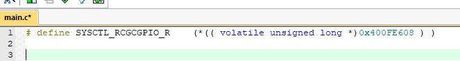
In GPIO configuration first method is to enable the clock of the peripherals. We will first define macros of all the registers containing the address of the requires pin needed for configuration and after that, we will assign them the values in the main code. Define a macro name it properly and give it a value of 0x400FE608 as shown in the figure below,
After clock enabling next step is to configure the mode control register of the GPIO port F because the LED is present on pin3 and the switch is present on pin 4 of port F. The address range of port F is from 0x4002500-0x40025FFF and binary bits that should be given to the data register are 0001000000 for pin 4 and 0000100000 for pin 3whose equivalent hexadecimal number is 0x40 and 0x20 respectively thus the addresses will be 0x4002500+0x40 for read register (input) and 0x4002500+0x40 for data write register (output), as shown in the figure below,

We have separate register for pin 4 and pin3 because one pin is to be configured as input and other as output. Next step is to configure the direction register of port F. Define a macro name it properly and assign it a value of 0x40025400 which is the address allocated to direction register in memory as shown in the figure below,
After that the next register to be enabled is digital enabling register the address of which is 0x4002551C as shown in the figure below,

An additional step while working with switches is to configure the PUR (Pull up resistor) register. In TIVA when we press a button it will complete the connection of the circuit by connecting it to the logical low level i.e. by connecting it to the ground. The purpose of enabling the pull-up resistor is that when no external device connected to the GPIO is active, the pull up resistor will automatically be connected to logic high level making sure that the connection will not complete. The register to be enabled here is pull up resistor register the address of which is 0x40025510 as shown in the figure below,

Now comes the part of assigning values, the clock of port F gating control is assigned a value of 0x20 hence the macro of clock will be given a value of 0x20. The value 0x08 (1000) will set the pin 3 of port F in the enable register and value 0x10 will set pin 4 of port F as shown in the figure below,

Now considering the bouncing effect of the switch, we need to solve it in the software. Easiest way to solve the issue created by bouncing effect is to insert a delay after the switch is checked for it state, the figure below shows the function that will be called to insert a delay of required time.

Where SYSTEM_CLOC_FREQUENCY is the frequency of the system. And DELAY_DEBOUNCE is a variable greater than the minimum time for which the switch can be pressed. Now lets’ move to the main code of the program. In the main code we will first assign the value of the cock to the register to which we specified the clock address as shown in the figure below,
The “|=” operator is an OR operator and it will simply add the value at the right to the variable given at the left and “&=” operator is an AND operation with a negation (~) sign i.e. it will that the bit wise NOT of value at the right and afterward AND it to the values in the left side of assignment operator. Simply it will reset the bits in the direction register as shown in the figure below,

First statement is the clock initialization of port F, second statement will enable both the pins 3 and pin 4 of port F, third and fourth statements are used to set the direction of the pins as output and input respectively and the last statement is to enable the pull up resistor register for pin 4 i.e. the pin with switch. Next step in the main loop is a never ending while loop as shown in the figure below,
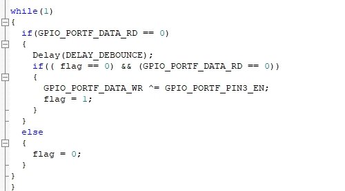
While (1) shows that the loop will continue to be executed forever. The first if statement will check the current state of the input switch. If the switch is not pressed then a delay of a specified time i.e. de-bouncing time of switch is added, and again the state of the switch is checked. If it has the same state as previously and the flag initialized as zero previously is zero, then the LED will be toggled (^ is to toggle the previous state of the pin) at the end of the if block the flag is updated to 1, and in the next iteration of while loop the else block will be executed and flag will be set to zero. In one iteration if block will be executed and in next iteration else will be executed. This is the edge triggering and if we are interested in level triggering simply remove the flag from the while loop.
Conclusion
In conclusion, this tutorial provided a comprehensive guide on using the general purpose input-output (GPIO) pins of the TM4C123 microcontroller as digital input pins. Using the TM4C123G TIVA launchpad, we demonstrated how to control an LED with the onboard push buttons. Building on our previous tutorial, where we covered the use of GPIO pins as digital output pins, this tutorial equips you with the necessary knowledge to effectively utilize the GPIO functionality of the TM4C123G6PM microcontroller. If you haven’t yet explored the use of digital output pins on the TIVA launchpad, we recommend reviewing that tutorial first for a more complete understanding.
You may also like to read:
- Accessing Memory Mapped Peripherals Registers of Microcontrollers
- SysTick Timer (System Timer) TM4C123G ARM Cortex M4 Microcontroller
- Nested Vectored Interrupt Controller (NVIC) ARM Cortex-M Microcontrollers
- UART Communication TM4C123 Tiva C LaunchPad with Example Codes
- I2C Communication TM4C123G Tiva C Launchpad
- ADC TM4C123G Tiva C Launchpad – Measure Analog Voltage Signal
How to toggle PF1 without registers i.e. creating a variable PF1 assigning the base-address and offset
Hello sir,
I wonder about what is the difference between GPIOF->DIR and GPIO_PORF_DIR_R
Are they C and C++?
nothing related to C++. Do you see both of these in a header file? Which ever one is in the header file…as long as either point to the address in the register map GPIODIR in the Tiva C datasheet.
buenas, quisiera saber como podria activar el sensor de temperatura externo en TIVA EK TM4C123GXL o si tiene un celular de contacto para que me apoyen.
with USR_SW1 it is working fine, but if i want to use USR_SW2, its not taking any inputs, i have updated GPIO data enable and direction properly for USR_SW2.
please help understanding how to use SW2