This MSP430G2 LaunchPad getting started tutorial walks you step by step through programming the TI MSP430G2 LaunchPad (MSP-EXP430G2ET) using the Energia IDE. By the end of this guide you will understand the LaunchPad hardware, install and configure Energia, upload your first LED-blink sketch, and read the onboard push button over serial — the four foundations every later MSP430G2 project in this series will build on.
The MSP430G2 LaunchPad is one of the most popular entry-level development boards from Texas Instruments. It is powered by the 16-bit MSP430 ultra-low-power RISC architecture — not ARM — and is designed specifically for battery-operated, energy-efficient embedded applications. The board comes in a DIP package that makes breadboarding and through-hole soldering trivial, runs at up to 16 MHz, and is fully supported by Energia, a beginner-friendly IDE that feels almost identical to the Arduino IDE. If you are new to microcontroller programming or migrating from Arduino, the MSP430G2 is one of the gentlest ways to get into low-power MCU development.
Recommended Components
The following components are used in this project or are helpful for getting started with MSP430 LaunchPad development.
| Component | How it’s used in this project | Buy on Amazon |
|---|---|---|
| MSP430G2 LaunchPad | The MSP-EXP430G2 LaunchPad (MSP430G2553) used in this project. | Check Price |
| Mini-USB Cable | Type-A to Mini-B cable to program and power the LaunchPad over USB. | Check Price |
As an Amazon Associate we earn from qualifying purchases. Prices and availability are accurate as of the date/time indicated and are subject to change.
What You Will Learn
- What the MSP430G2 LaunchPad is and how its 16-bit MSP430 architecture differs from ARM-based boards
- The key features and technical specifications of the MSP430G2553 and MSP430G2452 microcontrollers that ship with the kit
- The complete header pin map of the MSP430G2 LaunchPad and how Energia pin numbers map to the MSP430G2553 GPIO ports (P1.x, P2.x)
- How to download, install, and set up Energia IDE on Windows, macOS, or Linux
- How to install the LaunchPad USB drivers and verify the COM port in Device Manager
- How to select the correct board (MSP430G2553) and serial port in Energia
- How to upload your first LED blinking sketch to the MSP430G2 LaunchPad
- How to read the onboard push button and stream its state to the serial monitor
- How to troubleshoot the most common MSP430G2 LaunchPad setup issues
Prerequisites and Required Components
- MSP430G2 LaunchPad (MSP-EXP430G2 or MSP-EXP430G2ET) — both work identically for this tutorial
- Mini USB cable (older LaunchPads) or Micro USB cable (newer G2ET revision) — this provides both power and programming
- A computer running Windows, macOS, or Linux
- Energia IDE — free, open-source, based on the Arduino IDE
- Basic familiarity with C programming (helpful but not strictly required)
You do not need any external components for this first tutorial — everything runs on the LaunchPad’s onboard LEDs and push button.
MSP430G2 LaunchPad Features and Technical Specifications
When you buy an MSP430G2 LaunchPad kit, it usually ships with two microcontrollers in a socket-friendly DIP package: the MSP430G2553 and the MSP430G2452. You physically swap them in and out of the ZIF socket on the board depending on the features you need. The table below (from the original Texas Instruments datasheet) compares the key specifications of both chips:

As the table shows, the MSP430G2553 is the stronger of the two chips — it has more Flash, more RAM, more timers, a hardware UART, an onboard ADC, and a real SPI/I2C interface. For the overwhelming majority of projects in this MSP430G2 series on Microcontrollerslab, we will use the MSP430G2553. Keep the MSP430G2452 as a backup or for extremely low-power designs.
Key MSP430G2553 specifications at a glance:
- Architecture: 16-bit MSP430 RISC CPU (not ARM)
- Maximum clock speed: 16 MHz (internal DCO, no external crystal required)
- Program memory: 16 KB Flash
- Data memory: 512 bytes SRAM
- GPIO: 16 general-purpose I/O pins across Port 1 and Port 2
- ADC: 10-bit, 8 channels
- Timers: 2 × Timer_A modules with capture/compare
- Serial: USCI module supporting UART, SPI, and I2C
- Supply voltage: 1.8 V – 3.6 V (3.3 V on the LaunchPad)
- Active current: ~230 µA at 1 MHz, 2.2 V — genuinely ultra-low-power
For a complete visual walkthrough of the LaunchPad hardware, watch this video:
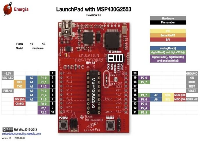
MSP430G2553 Pin Mapping on the MSP430G2 LaunchPad
Understanding the pin map is essential because Energia uses header pin numbers — not the MSP430G2553’s native port names like P1.0 or P2.3 — to identify pins in code. This keeps your sketches portable across all TI LaunchPads, but it takes a minute to learn.
The rule of thumb: you use the physical pin number printed on the board silkscreen as the identifier in Energia functions. For example, to declare P1.0 (the red onboard LED) as a digital output, you do not write pinMode(P1_0, OUTPUT) — you write:
pinMode(2, OUTPUT);
Header pin 2 maps to P1.0 on the MSP430G2553. The table below lists the complete pin map for every header pin on the MSP430G2 LaunchPad, so you can look up which physical header pin corresponds to which MSP430G2553 GPIO at a glance. Because these header numbers are consistent across every TI LaunchPad, using them in your code guarantees portability when you later move to a TM4C123 Tiva or other LaunchPad board.
| Header Pin Number | MSP430G2553 Pin |
|---|---|
| 1 | 3.3 V |
| 2 | P1.0 |
| 3 | P1.1 |
| 4 | P1.2 |
| 5 | P1.3 |
| 6 | P1.4 |
| 7 | P1.5 |
| 8 | P2.0 |
| 9 | P2.1 |
| 10 | P2.2 |
| 11 | P2.3 |
| 12 | P2.4 |
| 13 | P2.5 |
| 14 | P1.6 |
| 15 | P1.7 |
| 16 | Reset pin |
| 17 | Test |
| 18 | P2.6 |
| 19 | P2.7 |
| 20 | Ground |
From now on in this MSP430 series we refer to pins by their header number rather than by their P1.x/P2.x port name, because Energia expects it and because it keeps your sketches portable.
How to Download and Install Energia IDE
We will use Energia IDE throughout this MSP430G2 tutorial series because it is by far the friendliest environment for beginners. The alternative IDEs — Code Composer Studio (CCS) and Keil µVision — are powerful but require you to work at the register level, which is a steep learning curve if you are just starting with MSP430 microcontrollers. Energia hides the register-level complexity behind Arduino-style functions like digitalWrite(), analogRead(), and Serial.begin(), while still giving you full access to every MSP430 peripheral.
Even better, Energia’s function library is nearly identical to the Arduino IDE. If you already know how to write Arduino sketches, you can pick up MSP430 programming in an afternoon. Follow these steps to install Energia:
- Open your browser and go to http://energia.nu/download/.
- Choose the installer that matches your operating system — Energia supports Windows, macOS, and Linux.
- Download the appropriate ZIP or installer package (this tutorial uses the Windows version, but every step below works identically on macOS and Linux).
- Copy the downloaded file to a convenient location on your machine.
- Extract / unzip the archive. You will see the complete Energia folder with the application and all its libraries.
- Optionally, right-click the energia.exe icon and create a desktop shortcut.
- Double-click the Energia icon to launch the IDE for the first time.
- You have now successfully installed Energia IDE and are ready to program your MSP430G2 LaunchPad.
If you run into any issues with installation, this video walks through the process visually:
How to Upload Code to the MSP430G2 LaunchPad Using Energia IDE
Now that Energia is installed, let’s connect the MSP430G2 LaunchPad and upload our first sketch. Before anything else, the LaunchPad’s USB drivers must be installed so your computer can communicate with the onboard programmer over USB.
Connect the LaunchPad to your computer using the USB cable. On most modern Windows 10 and Windows 11 systems, the drivers install automatically — you will hear the USB connection chime and see a notification that the device is ready to use. If automatic installation fails, you can download the drivers manually from the TI website (search “MSP430 LaunchPad drivers”) and install them as a fallback.
Once the drivers are in place, open Energia and follow these steps to upload your first sketch:
- Go to Tools → Serial Port and select the COM port that the LaunchPad enumerated on. On Windows it will typically be named something like “MSP430 Application UART (COMx)”.
- Go to Tools → Board and select MSP430G2553 (or MSP430G2452, depending on which chip is in the socket).
- Open an example sketch — File → Examples → 01.Basics → Blink is the canonical first test.
- Click the Verify button (the checkmark) to compile the sketch and confirm the code is error-free.
- Click the Upload button (the right arrow) to flash the code to the LaunchPad.
- After “Done uploading” appears at the bottom of the Energia window, you should see the onboard red LED blinking at 1 Hz.
That is all there is to the upload workflow. You are now running compiled C code on the MSP430G2553 microcontroller — congratulations. Don’t worry about understanding the Blink sketch itself yet; we will break it down in the next section, and the full GPIO tutorial (linked at the end of this article) goes into every register and every Energia function in depth.
For a video walkthrough of the upload process, see:
Getting Started with Your First MSP430G2 LaunchPad Project
Before running any code, there are a few hardware checks that save a lot of frustration later. The MSP430G2 LaunchPad has gone through several PCB revisions (Rev 1.4, 1.5, and the newer G2ET revision) with minor differences in jumper layout — so take a moment to verify the following:
- Jumpers are in their default factory positions. Wrong jumper placement causes unpredictable behavior — the LaunchPad may fail to enumerate on USB, or programming may fail silently. The jumper block labelled J3 controls whether the ST-Link-like emulator is connected to the target MCU; leave all jumpers in place for first-time use.
- On Rev 1.5 boards, the TXD/RXD jumpers can be set for either hardware UART or software UART. For the MSP430G2553 (which has a real hardware UART), orient the jumpers for hardware mode — this is the default and what every Energia example expects.
- The green power LED lights up at the top of the LaunchPad as soon as you plug in the USB cable. If it does not, either the cable is a charge-only cable (try another one) or the USB port is not delivering power.
With hardware verified, open Energia and confirm your Tools → Board setting is LaunchPad w/ MSP430G2553 (16MHz), and Tools → Serial Port shows the LaunchPad’s COM port. If the serial port menu is empty or greyed out, the drivers have not installed correctly — go back through the driver installation steps. If everything is green, you are ready to run the first real example.
LED Blinking Example with the MSP430G2 LaunchPad
The MSP430G2 LaunchPad has two onboard user LEDs — a red LED connected to P1.0 (header pin 2) and a green LED connected to P1.6 (header pin 14). We will use the red LED for our first blink test.
Go to File → Examples → 01.Basics → Blink in Energia to open the canonical LED blinking sketch. Click Upload. If everything is set up correctly, the red LED starts blinking at 1 Hz (on for one second, off for one second) almost immediately after “Done uploading” appears. If the LED blinks, your hardware, driver, and IDE configuration are all working — you are ready to move on to real projects.

If the LED does not blink, go back carefully through the hardware setup, driver installation, and board selection steps above — 99% of first-time MSP430 LaunchPad problems trace back to one of those three.
How to Use the Onboard Push Button with the MSP430G2 LaunchPad
Now let’s try the onboard push button. The MSP430G2 LaunchPad has one user push button labelled S2 (Push Button 2), wired to P1.3 — which is header pin 5 in Energia. We will read its state and stream the result over serial to the PC.
Open File → Examples → 01.Basics → DigitalReadSerial in Energia. This is a great first example because it teaches three things at once: how to read the onboard push button, how to use the LaunchPad pin map to find the right pin, and how to use Energia’s serial monitor for debugging.
Change the pushButton variable in the sketch to 5 (the Energia header pin number for P1.3). You can also write P1_3 if you prefer — note the underscore, because the period character (as in P1.3) is reserved in C. Both refer to the same physical pin.
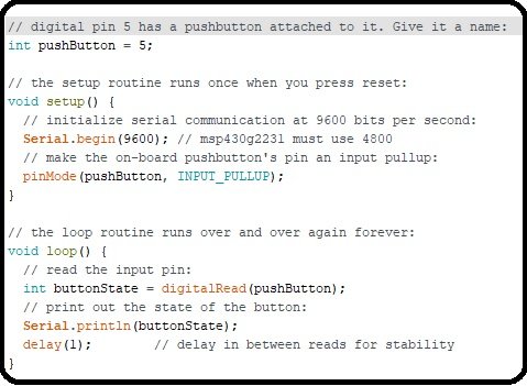
How the Push Button Code Works
- In the
setup()function,Serial.begin()starts UART communication at a chosen baud rate. The MSP430G2553’s hardware UART supports common rates up to and beyond 115200 baud — the example uses 9600 only because that is the Arduino/Energia default, not because 9600 is a hardware limit. Whatever baud rate you pick, the serial monitor must match or you will see garbage. pinMode(pushButton, INPUT_PULLUP)configures P1.3 as an input with the internal pull-up resistor enabled. With pull-up active, the pin reads HIGH when the button is released and LOW when the button is pressed — the opposite of what you might expect, but standard for pull-up wiring.- In the
loop(),digitalRead(pushButton)returns the current state of the pin, andSerial.println()prints that state over UART. - Click Verify, then Upload.
- Once upload finishes, click the magnifying-glass icon in the top-right corner of Energia to open the Serial Monitor.
- Make sure the baud rate dropdown at the bottom of the Serial Monitor matches the rate in your
Serial.begin()call — mismatched baud produces unreadable characters. - If no data appears at all, check that Tools → Serial Port still has the correct COM port selected — some USB hubs re-enumerate the port when the monitor opens.
- You will see a stream of
1and0values:1when the button is released (pulled high) and0when the button is pressed (pulled low through the switch).
That’s it — you have now written and read GPIO on the MSP430G2553 microcontroller and confirmed the full programming-to-serial-monitor loop works end-to-end. From here every MSP430 peripheral (PWM, ADC, UART, LCD, sensors) follows the same pattern: set a pin mode, call the right Energia function, read or write data.
Troubleshooting Common MSP430G2 LaunchPad Issues
- Serial port not listed in Energia. The USB drivers are not installed. On Windows, open Device Manager — if you see an unknown device with a yellow triangle, right-click it and select “Update driver”. Install the TI MSP430 LaunchPad drivers from the TI website as a manual fallback.
- “Can’t open device” error during upload. Another program (a serial terminal, another Energia window, or an old uploader) is holding the COM port. Close every other application that might be using the port and retry.
- Code uploads but LED does not blink. Wrong board selected in Tools → Board. Make sure you picked MSP430G2553 (or MSP430G2452) and not a different MSP430 variant.
- Green power LED is off. Bad USB cable — many Mini USB cables are charge-only with no data lines. Try another cable or a different USB port.
- Serial monitor shows garbage characters. Baud rate mismatch between your sketch and the Serial Monitor. Set both to the same value (9600 for most Energia examples).
- Push button always reads HIGH or always reads LOW. You forgot
INPUT_PULLUPinpinMode(), so the pin is floating. Add the pull-up and the readings will stabilize. - LaunchPad Rev 1.5 hardware/software UART confusion. Orient the TXD/RXD jumpers on J3 for hardware UART mode when using the MSP430G2553 with Energia — software UART mode is for older revisions without a hardware UART.
Frequently Asked Questions
Is the MSP430G2 LaunchPad based on ARM?
No. The MSP430G2 LaunchPad uses a 16-bit MSP430 RISC CPU designed by Texas Instruments, not an ARM core. MSP430 is a separate architecture optimised for ultra-low-power battery-operated applications. If you want an ARM-based TI LaunchPad, look at the Tiva TM4C123 (Cortex-M4) or the MSP432 (Cortex-M4F).
Can I program the MSP430G2 LaunchPad with the Arduino IDE?
Not directly — the Arduino IDE does not include an MSP430 toolchain. Energia is essentially “Arduino IDE for TI LaunchPads”: it uses the same Wiring/Arduino function library (pinMode(), digitalWrite(), Serial.begin(), etc.) but swaps the AVR toolchain for the MSP430 toolchain underneath. Sketches written for Arduino Uno often compile and run on the MSP430G2553 with zero changes.
What is the maximum UART baud rate on the MSP430G2553?
The MSP430G2553 hardware UART supports standard baud rates well beyond 9600 — including 19200, 38400, 57600, and 115200. The commonly-quoted “9600 max” figure refers to the Energia example default, not a hardware limit. For higher baud rates, simply pass the desired rate to Serial.begin().
Which LED pins are used on the MSP430G2 LaunchPad?
The red onboard LED is on P1.0 (Energia pin 2) and the green onboard LED is on P1.6 (Energia pin 14). Note that the green LED shares its pin with the I2C SCL line on the MSP430G2553, so you may need to remove the LED jumper on J5 when using I2C.
What is the difference between MSP430G2553 and MSP430G2452?
The MSP430G2553 has 16 KB Flash, 512 bytes RAM, hardware UART/SPI/I2C, and a 10-bit ADC. The MSP430G2452 has 8 KB Flash, 256 bytes RAM, no hardware UART, and a 10-bit ADC. Use the G2553 for every project in this series — it is strictly more capable and both chips are included in the LaunchPad kit.
Do I need external power for the MSP430G2 LaunchPad?
No — the LaunchPad is powered entirely from the USB cable during development. For standalone battery-powered projects you can remove the MSP430G2553 from the DIP socket and run it from any 1.8 V – 3.6 V supply (two AA cells, a CR2032 coin cell, or a LiPo battery).
Conclusion
You now have a fully working MSP430G2 LaunchPad setup: Energia IDE installed and configured, USB drivers working, the correct board and COM port selected, your first LED blinking sketch uploaded, and the onboard push button streaming data to the serial monitor. More importantly, you now understand the four things every later project in this series depends on — the MSP430G2553 features, the header-pin-to-GPIO mapping, the upload workflow, and the basic digital I/O pattern.
From here you are ready to move on to real projects using the MSP430G2553 microcontroller — GPIO, PWM, ADC, UART, LCD interfacing, sensor integration, and more.
How to Declare Variables in Energia IDE
How to Use Functions in Energia IDE
Related MSP430G2 LaunchPad Tutorials
- How to Use Input Output Pins of MSP430G2 LaunchPad
- RGB LED Interfacing with MSP430G2 LaunchPad
- Motion Sensor Interfacing with MSP430G2 LaunchPad
- LCD Interfacing with MSP430 LaunchPad
- UART Serial Communication with MSP430 Microcontroller
- How to Use ADC of MSP430 Microcontroller
- Pulse Width Modulation using MSP430 LaunchPad – Control LED Brightness