In this tutorial, we will discuss the workings of RS232 serial communication. The introduction of RS232 was made in 1962 by the Radio Sector of the EIA. With the invention of electronic devices such as printers, computers, laptops, etc., the researchers thought that the manufacturing of some devices should be to provide communication between these devices. So, this was the reason for the adoption of RS232 as a standard to carry out digital communication as well as data exchange. With the help of RS232, the exchange of data is more reliable than on analog channels. This standard already defines the voltage levels, thus making it immune to noise disturbances as well as reducing data exchange errors. RS232 has many applications in microcontroller-based projects and embedded systems projects.
Introduction to RS232
The use of RS232 has become a standard for carrying out communication in order to link computers as well as their peripheral devices that allow serial data exchange. The basis of RS232 is to define the voltages for the path that it uses for data exchange purposes among various devices. Signal level as well as common voltages, the configuration of the common pin, and the control signals are specified. The design of this standard was basically for modems and teletypewriters. Thus, it doesn’t provide support for several elements like framing of characters, character encoding, error detection protocols, etc. that are mandatory whenever data transfer is going to take place. Without providing support for such devices, this standard cannot be adopted to carry out data transfer. So, in order to overcome this issue, an integrated circuit known as UART, i.e., “Universal Asynchronous Receiver Transmitter”, is used with RS232.
Implementation of RS232
The RS232 interface works in conjunction with the UART that is integrated in the controller or processor. The bytes are being taken, and thus individual bits are being transmitted in a sequential manner inside a frame. A frame can be thought of as a defined structure that carries a meaningful byte or bit sequence of data. The data flow starts with the start bit, which is further followed by eight data bits, a stop bit, and a parity bit.
Data from UART to RS232
Once the alignment of data in this way is complete, the separate line drivers play their role in the conversion of the UART logic family to the RS232 logic. In the final phase, the signals transmit at the specific voltage level of RS232. The transfer of these bits is carried out in a sequential manner, i.e., the data bits are sent one after another. This mode of data transfer also requires that the receiver side be aware of receiving the actual bits of data so it can synchronize with the coming data.
As the starting bit, logic 0 is sent, which is used to signal the receiver that new characters are coming. Once this is acknowledged by the receiver, the next 5 to 8 bits are sent, followed by the parity bit. The parity bit is used for error detection. The parity bit can be specified using the odd or even numbers of 1s present in the data, and the same calculation is also done on the receiving side. Then the received and calculated parity bits are compared. If both are the same, then the decoding of the data is performed; otherwise, the data is discarded if both are not the same. The parity bit is followed by the stop bit, which shows that the data transmission process is complete and there is no more data to be sent.
RS232 Specifications
RS232 is considered a complete standard. Perfect compatibility is ensured by RS232 by not only defining the electrical characteristics but also the mechanical and functional characteristics. For instance, slew rate, pin identification, signaling rate, voltage levels, pluggable connectors, etc. All of these specifications, as well as their values, are mentioned in the block diagram below:

Electrical Characteristics of RS232
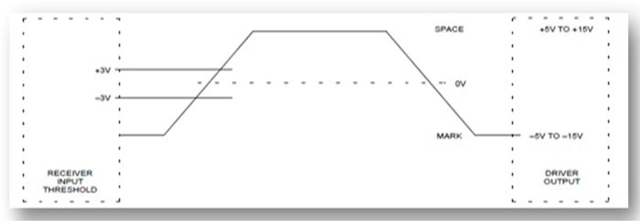
The electrical characteristics include the voltage level, voltage withstand level, and slew rates. The different voltage levels represent the pin-out signals of RS232 with respect to the common pin voltage. The maximum voltage specified by RS232 comes out to be 25 volts. On the transmitter side, the output voltage level of the driver is specified as +3 volts and +5 volts for the high levels. For low levels, -3 volts and -15 volts are specified. On the receiver side, the same voltage levels are observed, i.e., for high levels, +3 and +15 volts, and for low levels, -3 and -15 volts. However, at the receiver side, the +2 volts are provided as a noise margin.
Between the +3 and -3 voltages is the dead area, i.e., its design is for absorption. The low voltage area represents an ON state, i.e., logic 1, and consider the high voltage area as an OFF state, i.e., logic 0. We refer to the low-voltage areas as marking, and the high-voltage areas as spacing. The maximum slew rate that is allowed in RS232 is 30 volts per microsecond, so the fall as well as rise time is slowed down and cross talk is significantly reduced. The following figure represents the logic specifications of RS232:
Mechanical Characteristics of RS232
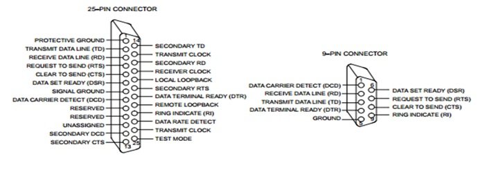
As far as the mechanical interface of RS232 is concerned, initially a 25-pin connector was being used. The minimum connector size specified by RS232 is capable of accommodating all the signals. Every pin is pre-defined in order to check the compatibility among the peripheral systems as well as the host. The male connector is used by the data terminal equipment, and for the female connector, the data communication equipment is used. The type of gender is another important concept regarding the connector. In mechanical as well as electrical trades, each connector comes as a pair, i.e., one female and one male connector. The pins of the male connector are sticking out, while in the case of the female connector, it has holes so that it can hold the male connector.

Previously, a 25-pin connector was widely used, but presently, 9-pin connectors are being used in many applications.
Functional Characteristics of RS232
The different signals that are being used in the interface are defined in this section. The signals can be categorized into four groups: common, timing, data, and control signals. We will discuss some of the terminologies, such as look back, secondary channel, and off hook, below:
- Loop Back: It allows users to test to ensure that their network is properly functioning.
- Off Hock: This condition occurs mostly during the communication or dialing phase. It prevails whenever a separate receiver is used that hangs on the hook switch until it is needed by the user.
- Secondary Channel: Secondary channels are regarded as data channels. For instance, secondary received data, secondary carrier data, and secondary transmitted data.
Presently, many new developments are being made, but RS232 is still used in many applications. The reason for using RS232 lies in the simplicity of this standard, which allows users to use it for direct communication from its serial ports. Various fields like automation, laboratories, and surveying play vital roles in sustaining the demand for RS232. Along with RS232, serial ports are being used for communicating with the headless system, i.e., a server without the installation of a keyboard during the boot process, which signifies the importance of RS232. That’s all for this article. Feel free to ask any question regarding this article in the comment section below.
Conclusion
In conclusion, this tutorial provides an in-depth overview of RS232 serial communication. It covers introduction, implementation, specifications, and electrical, mechanical, and functional characteristics. Hopefully, this was helpful in expanding your knowledge of RS232 serial communication.
You may also like to read:
- RS485 Serial Communication between ESP32 and ESP8266
- RDM6300 RDM630 RFID Reader with ESP8266 NodeMCU
- How to use FTDI USB to Serial Converter Cable ( Linux+Windows)
- Max232 IC pinout, features, pins description, and example
- How to Make Call using GSM Module on Mobile Phone
- ESP32 ESP-NOW Two way Communication (Arduino IDE)
- ESP32 I2C Communication Set Pins, Multiple Devices Interfaces and Change Pins
- STM32 Blue Pill UART Communication Tutorial with CubeIDE and HAL Libraries
- ESP32 ESP-NOW Send Data to Multiple boards (One to Many Communication)
- STM32 Blue Pill UART DMA with STM32Cube IDE and HAL Libraries
- STM32 Blue Pill UART Interrupt with CubeIDE and HAL Libraries
This concludes today’s article. If you face any issues or difficulties, let us know in the comment section below.