RS232 standard was used to transfer data between two devices as serial communication. This standard was introduced by TIA/EIA, which was also known as TIA/EIA 32. RS232 has some limitations. It was unable to communicate with TTL/CMOS. To solve this issue and IC named “MAX232” was introduced by “Maximum Integrated Product” in 1987.
Recommended Components
The following parts are used in this article, along with a generic electronics kit that is handy for building and testing the circuit.
| Component | How it’s used | Buy on Amazon |
|---|---|---|
| MAX232 RS-232 driver/receiver IC | The RS-232 level converter IC this tutorial covers, DIP-16. | Check Price |
| Electronic component assortment kit (1390 pcs) | A handy assortment of resistors, capacitors, LEDs, diodes and transistors for building circuits. | Check Price |
| Digital multimeter (AstroAI) | Measures voltage, current, resistance and checks continuity while you build and debug. | Check Price |
| Breadboard | Solderless base for prototyping the circuit. | Check Price |
| Jumper Wires | Make the connections on the breadboard. | Check Price |
As an Amazon Associate we earn from qualifying purchases. Prices and availability are accurate as of the date/time indicated and are subject to change.
Max232 Introduction
MAX232 was one of its kind, which was able to convert the TIA/EIA 32 signals to its voltage and logical levels. It comes with an internal two drivers and receivers. Each driver & receiver could convert the EIA/TIA signal to TTL/CMOS level. It works with capacitors and a single 5-volt power supply. A single power supply used by the IC to convert any incoming signal to its specific voltage level.
In MAX232 5-volt supply could be enough for TTL/CMOS device to communicate or conversion of its data from TIA/EIA 32, but it isn’t enough to power up the “TIA/EIA 32” device. To communicate and to solve the power problem for “TIA/EIA 32” capacitors are used by “MAX232” to solve this issue. “MAX232” has an ability to convert TIA/EIA 32 voltage single to 5-Volt signal for TTL/CMOS and vice versa. It is used for serial communication between microcontrollers and other devices. You may follow these articles:
- serial communication 8051 microcontroller using keil
- UART Serial communication with MSP430 microcontroller
- Arduino with Labview: Getting Arduino data through serial communication in labview
- SERIAL COMMUNICATION USING PIC16F877A MICROCONTROLLER
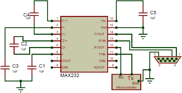
Pinout of Max232

PIN CONFIGURATION
| PINS | DESCRIPTION | |
|---|---|---|
| C1+ | Pin1 | Pin 1 – Pin 6 are used for Capacitors. The capacitor on Pin 2 – Pin 6 is used for storage of Charge and Other 2 are used to solve the power dissipation issue of TIA/EIA 32 devices. |
| Vs+ | Pin2 | |
| C1- | Pin3 | |
| C2+ | Pin4 | |
| C2- | Pin5 | |
| Vs- | Pin6 | |
| T2 out | Pin7 | It is a data input line. T2 pin is used for the transmission of data from RS232 to MAX232. |
| R2 in | Pin8 | It is a data output line for Max232. R2 pin is used for sending data from MAX232 to RS232. |
| R2 out | Pin9 | R2 is an output pin of MAX232. It is used for sending the data from MAX232 to UART Communication Devices. |
| T2 in | Pin10 | It is an input pin of MAX232. It is used for receiving the data from UART devices to MAX232. |
| T1 in | Pin11 | It is an input pin-like Pin 10. It is also used for receiving the data from UART devices. Pin 11 is used in case of a second UART device. |
| R1 out | Pin12 | R1 is an output pin-like Pin 9. It has the same transmission function for UART devices but it is used only in case of second UART device. |
| R1 in | Pin13 | R1 is used as an input line. It is also used as same as Pin 8, for receiving the data from “RS232” to “MAX232”. It is used in case of a second RS232 device. |
| T1 out | Pin14 | T1 is used as an output line. It is used to send the data from MAX232 to RS232 just like Pin 7. It is used only in case of multiple RS232 Devices. |
| GND | Pin15 | GND pin is used for Ground. Every RS232 and UART device ground should be common with GND. |
| Vcc | Pin16 | Vcc is used for Power Up the MAX232. Its voltage should not be more than 5 – 6V. Mostly 5V supply is used for its proper working. |
There are two drivers installed in MAX232 but always keep in mind, that when we will use the specific pins for RS232 then they will have to use the specific pin for UART. When we are using Pin 13 & 14 for RS232 then we have to use the Pin 11 & 12 for UART. This will go the same for communication of Pin 8,9,10 & 11.
FEATURES of Max232
- The first and easiest way to convert the EIA/TIA 32 to TTL/CMOS and vice versa by using only 5V power supply.
- Single 1.0uF capacitor used to solve the power decimation issue.
- It has two drivers and two receivers. Which can be used at the same time for the conversion of data between two different RS232 and TTL/CMOS devices.
- It is easy to set up and easy to initiate for all devices.
- Its Operating speed is almost equal to 120 Kbits/sec
- Sometimes RS232 devices have different voltage level. It could handle almost more than +30 volts.
- It operating current range is also equal to 8mA.
- MAX232 has 16-pins and it comes with multiple packing (PDIP, SO, SOIC).
- Its max working temperature is 150 C.
How and Where to use it?
Most of the microcontroller uses the TTL/CMOS to communicate with other devices. In some cases when microcontroller needs to communicate with those devices which have RS232 communication then we will need MAX232 to set up communication between them. To use the MAX232, we will need to follow some procedures.
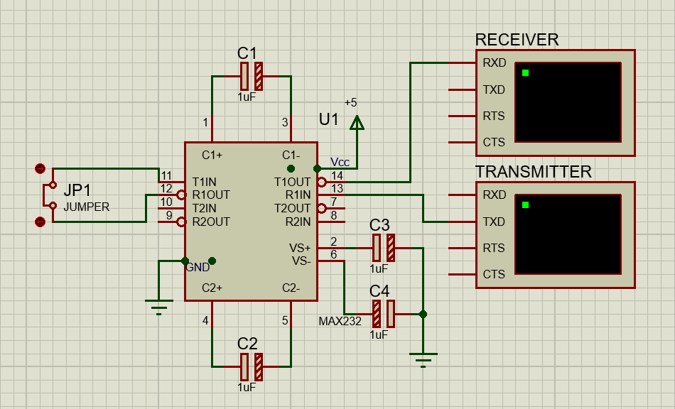
MAX232 has two transmission lines, “R1(IN & OUT), T1 (IN & OUT), R2(IN & OUT) and T2 (IN & OUT)”. Here we will use the “R1 & T1” only. R2 & T2” has the same procedure when we will need to use it. First Connect the RS232 device with “T1 out” and “R1 in”, then attach the “TTL/CMOS” device with “R1 out” and “T1 in”. Then attach the 1 uF capacitor at C1+, C2, and C2-, C2-. Always keep in mind that during using R1 and T1 only C1 capacitor will be necessary. After attaching the capacitor at C1 & C2 now attach two more capacitors at Vs- and Vs+.
Voltage Level Conversion
Now the communication can be stated. You may notice that when TTL/CMOS sends the data in 5V data then the RS232 device receives the data in up to +25 volt. This voltage conversion happens because of the capacitor used at Vs+ and Vs- helps the MAX232 to change the voltage from +5 volts to +25 volts. This conversion of voltage through the capacitor is called a charge pump. Don’t forget to attach the Vcc with +5 volt and make the ground common with MAX232.
Applications
- It is used mostly to connect microcontroller with computers.
- MAX 232 has wide use of converting every RS232 logic level to TTL/CMOS logic and vice versa.
- MAX232 is also used in Modems and battery-powered systems.
- RS232 based cables also used to convert the data in TTL/CMOS.
MAX232 Examples
In this example, we will send the data from TTL/COMS pin to MAX232 and receive back using the MAX232.
Sending and Receiving Data
In Proteus attach the MAX232 with capacitor and power as mentioned above. Then connect the MAX232 with Two virtual terminals for sending visualizing the data. Attach the sender with R1IN and receiver T1OUT. Now attach the jumper at T1IN and R1OUT. Here we will send the data through Serial Monitor, then it will convert to RS232, and then it will send it back to UART by using RS232 transmission pin. This time the data will be the same as it was.
Now run the simulation and start sending the data with a jumper open. You will notice that there will be no data at the output. It is because the data transmitting from T1 is not reaching to R1out.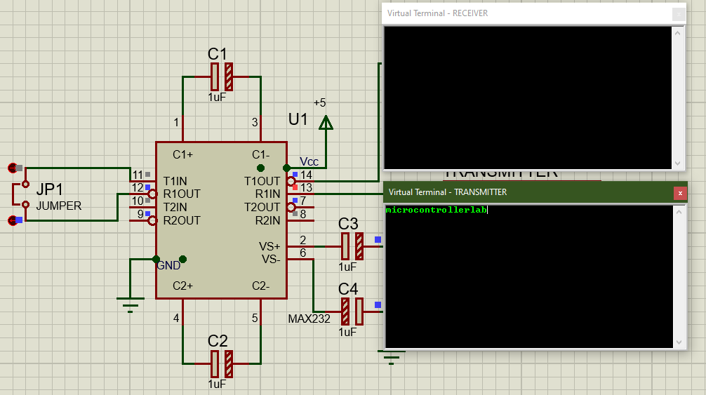
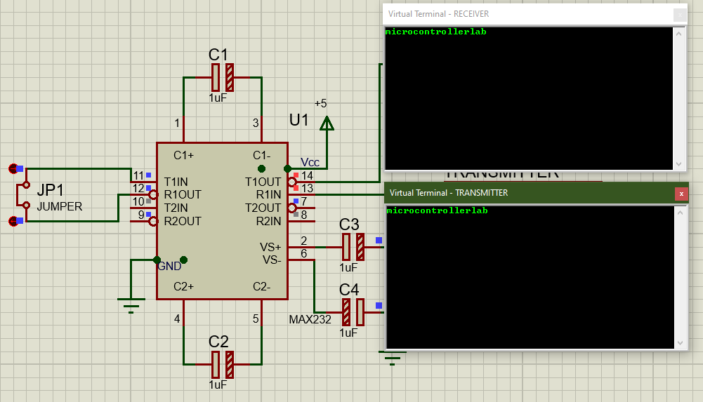
Now send the data with the jumper connected. You may notice that the data is received as it is sent to the output pins. It is because the circuit is fully connected and the data conversion speed is 120 Kbits/ sec which much faster for not only a human begin. It is also fast for communicating between machines.
Due to speed and size, MAX 232 has too much usage in our daily appliances. Even Some older companies which use the RS232 in the old days didn’t even change the circuit they start adding the MAX232 within the capable and start proving both communication system for their devices.
Can you please direct me on how to get the MAX232 library for Proteus?
Clear enough