In this tutorial, we will learn how to perform RS485 serial communication between ESP32 and ESP8266 boards using 5V MAX485 TTL to RS485 module. RS485 communication is used in industrial Modbus to communicate with various devices. We will follow the RS485 serial communication protocol and demonstrate it with ESP8266/ESP32 boards. The ESP8266 NodeMCU will act as the master and ESP32 will act as the slave. The master (ESP8266) will be connected with a potentiometer which will be used to vary ADC values. The slave node will receive this ADC data from the master over RS485 and control the brightness of an LED and also display a value on OLED. These ADC values will be transferred from the master to the slave via the RS485 module.
We have a similar guide with Arduino:
Recommended Components
The following components are used in this project or are helpful for building it with the ESP32.
| Component | How it’s used in this project | Buy on Amazon |
|---|---|---|
| ESP32 Development Board | Acts as one node of the RS485 bus in this project. | Check Price |
| ESP8266 NodeMCU (ESP-12E) | Acts as the second node communicating over RS485. | Check Price |
| Micro USB Cable | Programs and powers each board. | Check Price |
| Breadboard | Holds the boards and RS485 modules for wiring. | Check Price |
| Jumper Wires | Connect the UART lines and the A/B RS485 bus lines. | Check Price |
| MAX485 / RS485 module | Converts the ESP UART signals to the RS485 differential bus on each node. | Check Price |
As an Amazon Associate we earn from qualifying purchases. Prices and availability are accurate as of the date/time indicated and are subject to change.
RS485 Serial Communication
Serial communication concerns the transmission of data in a serial manner, meaning it is sent and received one bit at a time. It is the most basic form of electronic data transmission and was the primary form of communication between machines in the first generations of personal computers. Implementing serial communication functionality in an embedded system requires the developers and engineers involved to have an understanding of the underlying serial protocols used in this form of data transmission. The most common protocols you will come across are the RS232/RS422/RS485 standards.
The RS485 protocol is a form of asynchronous serial communication that allows communications bus to connect multiple devices simultaneously. The communication is at half duplex using two wires and common ground. It is faster and covers a wider range as compared to other standards like RS232 etc. Provides a maximum cable length of 1200m. Can connect to a maximum of 32 devices unlike RS232 that connects to a single device. Moreover, it is preferred in electrically noisy industrial environments as it is less prone to noise issues.
Differential signaling is used in this protocol to provide better noise immunity as well as recovering a lost signal at the end of a line. It works by putting the signal on 1 wire and the inverse of the signal on the other wire.
Apart from all the advantages listed above, the RS485 protocol successfully transfers data between devices over large distances making it an optimal choice to be used in industries.
MAX485 RS485 Transceiver Module
The MAX485 RS485 Transceiver Module is used when transferring data between microcontrollers. This transceiver module consisting of the Maxim MAX485 IC provides robust serial communication over long distances up to 1200m. The power efficient module transfers data in both directions at a maximum data rate of 2.5 Mbps.
Moreover, this 5V MAX485 TTL to RS485 module can easily be interfaced with microcontrollers for example Arduino, ESP32, ES8266 etc. as it uses 5V logic levels.
Some key features of RS485 Module include:
- Differential signalling for better noise immunity
- Covers distances up to 1200 meters
- Maximum data rate of 2.5 Mbps
- Supports up to 32 devices on same bus
- Red power LED
- 5V operating voltage
- Low Power Consumption
Pin Out
The MAX485 transceiver module consists of 8 pins, 4 on each side. They are shown in the figure below:
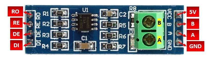
| Pin Name | Description |
| VCC | This is the power supply pin. It is connected with 5V that powers up the module. |
| A | This is the non-inverting receiver input and driver output. It is connected with A on the other module. |
| B | This is the inverting receiver input and driver output. It is connected with B on the other module. |
| GND | This is the GND pin. It is connected with the common ground. |
| RO | This is the receiver output pin. It is connected with the RX pin of the microcontroller. |
| RE | This is the receiver output enable pin. To enable, it is set at a LOW state. |
| DE | This is the driver output enable pin. To enable, it is set at a HIGH state. |
| DI | This is the driver input. It is connected with the TX pin of the microcontroller. |
The module also consists of 2 screw terminal blocks which are part of the output side.
A: This is the non-inverting receiver input and driver output. It is connected with A on the other module.
B: This is the inverting receiver input and driver output. It is connected with B on the other module.
RS485 Serial Communication between ESP8266 and ESP32 boards (Control LED Brightness)
Let us demonstrate an example of RS485 serial data transfer between an ESP8266 NodeMCU and a n ESP32 board using the MAX485 TTL to RS-485 module. Our aim will be to send ADC values from the master ESP8266 connected with a potentiometer through the RS485 module to the slave ESP32. The slave ESP32 will be connected with an LED and an OLED display. The brightness of the LED will vary with the ADC values generated by the potentiometer at the master side. Additionally, the OLED display will also print the current PWM values (0-255) as well.
Master and Slave Configuration Circuit Diagram
We will require the following components for this project:
Required Components
- 1 ESP8266 NodeMCU board
- 1 ESP32 development board
- 2 RS485 Modules
- 1 Potentiometer
- 1 LED
- 1 OLED display
- Connecting Wires
- Breadboard
In order to properly connect all the devices successfully follow the connections very carefully. Follow the schematic diagram below:
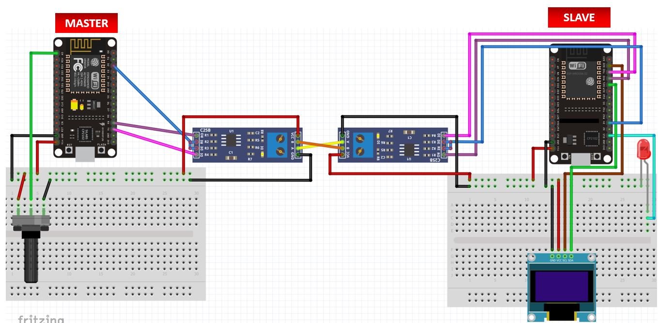

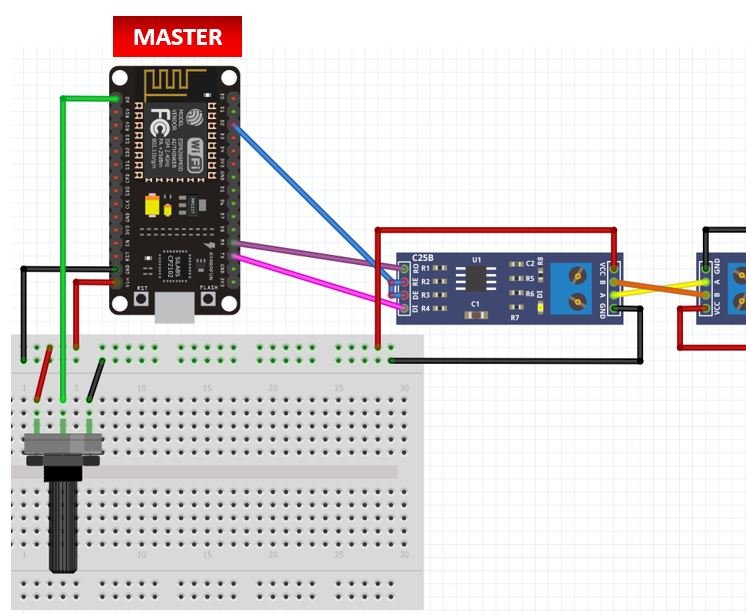
ESP8266 NodeMCU (Master) Connections
Firstly, we will explain the connections between the Master ESP8266. The master ESP8266 is connected with a potentiometer and a RS485 module. Out of the eight pins of the RS485 module we have connected 6 pins with the ESP8266 board.
Below you can view the connections between the NodeMCU and the transceiver module.
| ESP8266 | RS485 Module |
| Vin | VCC |
| GND | GND |
| RX | RO |
| D2 (GPIO4) | RE & DE |
| TX | DI |
Connect the VCC pin of the RS485 module with Vin pin of ESP8266. Additionally connect both the grounds together. The RO pin will be connected to the serial RX pin of ESP8266. Likewise, the DI pin will be connected with the serial TX pin of ESP8266. The RE and DE pins will be connected together with any GPIO pin of the board. We have used GPIO4 to connect these two pins.
The rest of the two pins of the RS485 module: B and A are connected with the other RS485 module’s B and A pins respectively that is connected with the ESP32 slave.
We have connected the potentiometer with the Analog pin A0 of our ESP8266 board. One terminal of the potentiometer is powered by Vin (red),the centre terminal is connected to A0 and the last one is grounded (black).
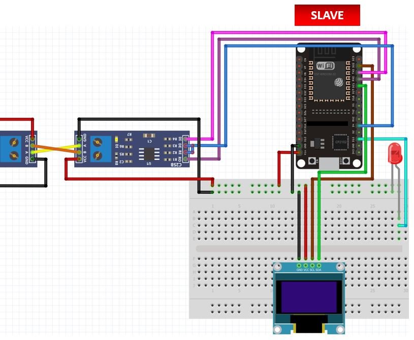
ESP32 (Slave) Connections
Next, we will explain the connections of the ESP32 slave with the RS-485 module, LED and the OLED display. The connections of the ESP32 board with the RS485 module are the same as NodeMCU. Just make sure to connect B and A of RS485 module (slave side) with B and A pins of RS485 module (master side) correctly.
Next, the OLED has four pins that we will connect with the ESP32 board. We will connect the VCC terminal of the OLED display with Vin which will be in common with the ESP32 board. SCL of the display will be connected with the default SCL pin of the ESP32 board that is GPIO22. SDA of the display will be connected with the default SDA of the ESP32 board that is GPIO21. Additionally the ground pins will be connected in common.
| Arduino UNO | OLED |
| GND | GND |
| Vin | VCC |
| GPIO22 | SCL |
| GPIO21 | SDA |
Moreover, we have connected the LED’s anode with GPIO15 (PWM enabled) and cathode with common ground. You can use any other PWM pin of the ESP32 board to connect with the LED as well.
Installing OLED Libraries in Arduino IDE
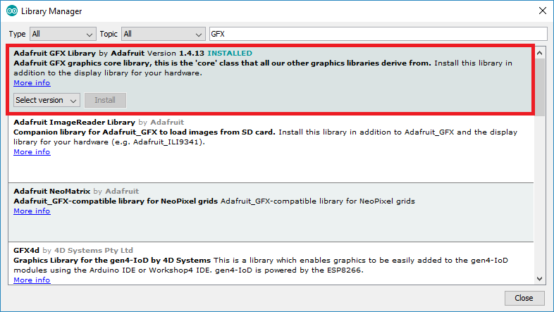
To use the OLED display in our project, we have to install the Adafruit SSD 1306 library and Adafruit GFX library in Arduino IDE. Follow the steps below to successfully install them.
Open Arduino IDE and click on Sketch > Library > Manage Libraries. Type ‘SSD1306’ in the search tab and install the Adafruit SSD1306 OLED library.

We will also require the Adafruit GFX library which is a dependency for SSD1306. Type ‘Adafruit GFX’ in the search tab and install it as well.
Arduino Sketch for ESP8266 Master
Open your Arduino IDE and go to File > New. A new file will open. Copy the code given below in that file and save it.
This sketch is for the ESP8266 that acts as the master. It will transfer ADC values through the RS485 module to the Slave.
int Enable_pin = 4;
int Analog_pin = A0;
int ADC_Value =0 ;

void setup()
{
  Serial.begin(115200);
  pinMode(Enable_pin, OUTPUT);
  pinMode(Analog_pin,INPUT);
  delay(10);
  digitalWrite(Enable_pin, HIGH);
}
void loop()
{
    int ADC_Value = analogRead(Analog_pin);
    Serial.println(ADC_Value);          //Serial Write ADC_Value to RS-485 Bus
    delay(100);
}
How the Code Works?
We will first define the ESP8266 GPIO pin that we have connected with DE and RE pins of the module. We have labelled it as the ‘Enable_pin’ and set the value 4 to it. This is the ESP8266 GPIO pin that we are using.
int Enable_pin = 4;Secondly, we will define two more variables. One will hold the ADC pin A0 that we will connect with the potentiometer. The second one will be called ‘ADC_value’ and will save the ADC values. Initially we have set the value to zero. The values will vary from 0-1023.
int Analog_pin = A0;
int ADC_Value = 0 ;
Inside the setup() function, we will open the serial communication at a baud rate of 115200. Then we will configure the enable pin as an output pin and the Analog pin connected with the potentiometer as an input pin. This will be achieved by using the pinMode() function and passing the pin as the first parameter and INPUT/OUTPUT as the second parameter.
Moreover, we will set the Enable_pin state to HIGH. This will make sure that DE and RE pins are both set to HIGH to enable the driver.
void setup()
{
  Serial.begin(115200);
  pinMode(Enable_pin, OUTPUT);
  pinMode(Analog_pin, INPUT);
  delay(10);
  digitalWrite(Enable_pin, HIGH);
}
Inside the loop() function, we will find out the ADC value according to the varying voltage using analogRead() after every 0.1 second. We will pass the ADC pin connected to the potentiometer as an argument inside it. This will be stored in the integer variable we defined previously ‘ADC_value.’ This will be sent to the RS-485 bus serially.
void loop()
{
  int ADC_Value = analogRead(Analog_pin);
  Serial.println(ADC_Value);          //Serial Write ADC_Value to RS-485 Bus
  delay(100);
}
Arduino Sketch for ESP32 Slave
Open your Arduino IDE and go to File > New. A new file will open. Copy the code given below in that file and save it.
This sketch is for the ESP32 that acts as the slave. It will receive the ADC values through the RS485 module serially from the ESP8266 master and control the LED brightness and OLED display accordingly.
#include <Adafruit_GFX.h>
#include <Adafruit_SSD1306.h>

int Enable_pin = 4;
int led_pin = 15;

const int frequency = 5000;
const int led_channel = 0;
const int resolution = 8;

Adafruit_SSD1306 display = Adafruit_SSD1306(128, 64, &Wire, -1);

void setup()
{
  Serial.begin(115200);
  pinMode(led_pin, OUTPUT);
  pinMode(Enable_pin, OUTPUT);
  digitalWrite(Enable_pin, LOW);        //  (LOW to receive value from Master)
  display.begin(SSD1306_SWITCHCAPVCC, 0x3C);
  display.display();
  delay(100);
  display.clearDisplay();
  display.display();
  display.setTextColor(WHITE);

}

void loop()

{
  while (Serial.available())
  {
    display.clearDisplay();
    int PWM_master = Serial.parseInt();
    int duty_cycle = map(PWM_master, 0, 1023, 0, 255);
    Serial.println(duty_cycle);


    ledcSetup(led_channel, frequency, resolution);
    ledcAttachPin(led_pin, led_channel);
    ledcWrite(led_channel, duty_cycle);

    display.setCursor(0, 0);
    display.setTextSize(2);
    display.print("MASTER PWM");

    display.setCursor(50, 30);
    display.setTextSize(4);
    display.print(duty_cycle);

    display.display();
    delay(100);

  }
}
How the Code Works?
Firstly, we will include the OLED libraries that we previously installed for the proper functionality of the OLED display.
#include <Adafruit_GFX.h>
#include <Adafruit_SSD1306.h>
Then we will create an integer variable for the ESP32 GPIO pin that we have connected with DE and RE pins of the module. We have labelled it as the ‘Enable_pin’ and set the value 4 to it. This is the ESP32 GPIO pin that we are using.
int Enable_pin = 4;We will define the ESP32 PWM pin that we have connected with the LED’s anode.
int led_pin = 15;
Next we will define the PWM parameters for ESP32. To do that first we will define the frequency of the signal. We have set it to 5000 Hz. Next, we will define the PWM channel. There are a total of sixteen PWM channels in ESP32. You can use any channel from 0-15. We have set the PWM channel to 0. Additionally, we have set the PWM resolution to 8 bits as it is the optimal resolution to obtain the maximum frequency. Although you can use resolution between 1-16 bits. As we are using 8-bit resolution, thus the duty cycle value will vary between 0-255. Duty cycle defines the width of the signal or ON time of the signal.
const int frequency = 5000;
const int led_channel = 0;
const int resolution = 8;
Now, we will create an object named display which will be handling the OLED display and specifying the width, height, I2C instance (&Wire), and -1 as parameters inside it.’ -1′ specifies that the OLED display which we are using does not have a RESET pin. If you are using the RESET pin then specify the GPIO through which you are connecting it with your development board.
Adafruit_SSD1306 display = Adafruit_SSD1306(128, 64, &Wire, -1);setup()
Inside the setup() function, we will open the serial communication at a baud rate of 115200. Then we will configure both the enable pin and the LED pin defined previously as output pins. This will be achieved by using the pinMode() function and passing the pin as the first parameter and INPUT/OUTPUT as the second parameter.
Moreover, we will set the Enable_pin state to LOW. This will make sure that DE and RE pins are both set to LOW to enable the receiver.
  Serial.begin(115200);
  pinMode(led_pin, OUTPUT);
  pinMode(Enable_pin, OUTPUT);
  digitalWrite(Enable_pin, LOW);        //  (LOW to receive value from Master)
We will initialize the OLED display by using display.begin(). Make sure you specify the correct address of your display. In our case, it is 0X3C.
Then, we will clear the buffer by using clearDisplay() on the Adafruit_SSD1306 object. Additionally, we will set the colour of the text as white.
  display.begin(SSD1306_SWITCHCAPVCC, 0x3C);
  display.display();
  delay(100);
  display.clearDisplay();
  display.display();
  display.setTextColor(WHITE);
loop()
Inside the loop() function, we will check if any data is available at the serial port. While the data is available, we will first clear the buffer of the display. Then we will map the ADC values received from ESP8266 from 0-1023 to values from 0-255. This will be stored in the integer variable ‘duty_cycle.’ The value will also get printed on our serial monitor.
  while (Serial.available())
  {
    display.clearDisplay();
    int PWM_master = Serial.parseInt();
    int duty_cycle = map(PWM_master, 0, 1023, 0, 255);
    Serial.println(duty_cycle);
We will use the following functions to configure PWM in ESP32. First by using ledcSetup(), we will initialize the PWM parameters. This function takes in three parameters. The channel number, frequency, and the resolution of PWM channel. Secondly we will use ledcAttach() to attach the led pin to the channel. Lastly, by using ledcWrite() we will generate the PWM with the duty cycle value. The value of duty cycle can vary between 0 and 255. That means, when the duty cycle value is 0, the LED will not glow at all and similarly when it is 255, LED will glow with full brightness.
  ledcSetup(led_channel, frequency, resolution);
  ledcAttachPin(led_pin, led_channel);
  ledcWrite(led_channel, duty_cycle);
The following section of code displays this PWM value sent by the master that was previously converted to 0-255, on the OLED display.
    display.setCursor(0, 0);
    display.setTextSize(2);
    display.print("MASTER PWM");

    display.setCursor(50, 30);
    display.setTextSize(4);
    display.print(duty_cycle);

    display.display();
    delay(100);
Demonstration
To see the demonstration of this project, upload the master and slave code to the respective ESP boards. But, before uploading code, make sure to select the Arduino from Tools > Board and also select the correct COM port to which the board is connected from Tools > Port.
For ESP8266:

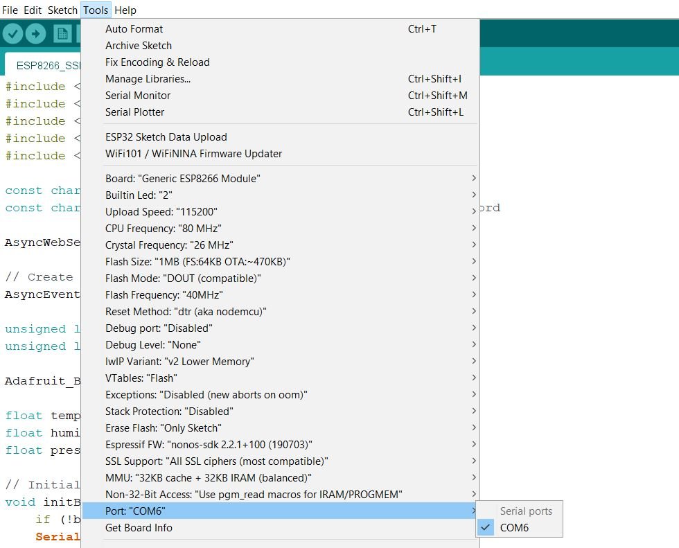
For ESP32:


Once the code is uploaded to the respective boards, turn the knob of the potentiometer and the brightness of the LED will vary. Increasing input values from the potentiometer act as increasing duty cycle hence the brightness of the LED increases. The OLED will display the current PWM values in the range 0-255 acquired from the master ESP8266 board as well.
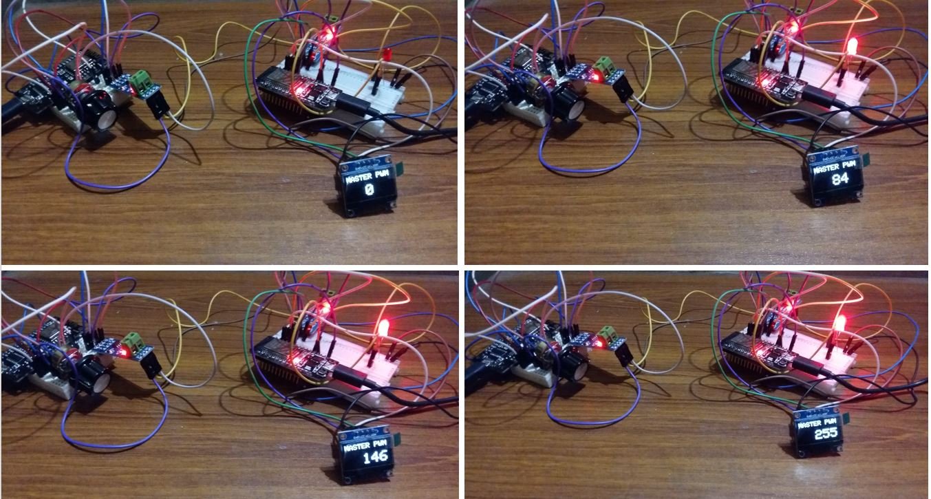
Video demo:
Thank you for very informative and well-organized lessons.
I was searching for an example of a half-duplex rs485 sketch.
Here, i could not understand why you tied the do and ro pins. i garher that you did this because you are only doing one-way communications. but then, only the do pin need be enabled on the master and the ro on the slave.
You can tie them together, because one of the Enable pins is inverted, as seen in the table at the top, with pins described. Having them both on H or L at the same time, you either enable receive or transmit mode on it.
You’d only benefit from having them separated if you would want to disable both, Rx and Tx entirely, which is not necessary in this and most cases.
I enjoyed reading your great article.
By the way, since the max485 outputs a 5V logic level, could it damage the esp MCU using 3.3V logic?
Using max3485 or max1348 seems appropriate.
Did you ever find an answer to this?
Hi, seems MAX3485 is ok but next problem: My Max3485 board has no Enable Pin, only TX, RX, Vcc, GND . What have i to do in this case (ESP8266)?
Very well done. Crisp and clear.
Thank you 🙏🏼
my project is two esp32 and two rs485 module is any libary to be installed for rs485