A bridgeless boost rectifier is a power electronic converter that converts AC voltages into DC voltages using only one inductor and capacitor. It combines the functionalities of a buck converter and a boost converter into a single-stage AC-to-DC converter. This converter is ideal for low voltage but high current energy harvesting applications, as it helps reduce the size of the overall power electronic circuit.
Circuit Overview
The bridgeless boost rectifier combines the buck and boost converter into a single circuit for converting the positive and negative half cycles of AC voltages into DC voltages. It utilizes only one inductor and capacitor to reduce the size of the power electronic converter.
Creating a MATLAB Simulink Model
To design and simulate the bridgeless boost rectifier for low-voltage energy harvesting applications, you can create a MATLAB Simulink model. Start by opening MATLAB and accessing the Simulink library browser. From there, you can search for specific power electronic component blocks and drag them onto the new model page. Components like the PWM generator, oscilloscope, inductor, capacitor, and others can be added to build the desired circuit. By following these steps, you can easily model and simulate the bridgeless boost rectifier for low-voltage energy harvesting in MATLAB Simulink.
To create a new model in MATLAB, follow these steps:
- Open MATLAB and click on the MATLAB Simulink library.
- This will open the Simulink library browser.
- Proceed to create a new circuit model in MATLAB.
Figure 1 MATLAB Simulink Library Browser
This MATLAB Simulink library browser contains all the user-related component blocks. To search for a specific component block, simply write the correct name of that component in the search menu bar. This will open the browser with all the related blocks for that component. When a user wants to create a new circuit, they can click on the “New Model” option in the menu bar. This will open a new page, as shown in Figure 2.
Figure 2 Figure 2 MATLAB Simulink New Model
Power Electronics Circuits in Simulink
In this new model page, the user can easily create any new circuit by finding the desired component blocks. For example, if the user wants to create a power electronics circuit, they can search for “power electronics” in the search menu bar. This will open a new page, as shown in Figure 3.
This page has all the power electronic components blocks as per the user’s requirements. Now the user can move these component blocks to a new model page either by dragging or by right-clicking on every block and then clicking on the option to add the block to a new model. The block will automatically shift to the new model page. Similarly, the user can easily search and drag all these other component blocks such as PWM generator, Oscilloscope, inductor, and capacitor, etc. By following these instructions, the user can easily create any new circuit or model in MATLAB Simulink. Similarly, to create a bridgeless boost rectifier for low voltage energy harvesting applications, the user will first create the circuit according to the block diagram of the bridgeless boost rectifier for low voltage energy harvesting applications shown in Figure 4.
Working
The design of this bridgeless boost rectifier is aimed at low voltage energy harvesting applications in power electronic converters. It operates in four modes. In mode one, both switches Q1 and Q2 simultaneously turn on. When both switches are turned on, they charge the inductor and reverse bias both diodes. In mode two, switch Q1 turns on while Q2 turns off, and diode D2 becomes forward biased. The inductor discharges and provides voltage to the output load. This process occurs during the positive half cycle of the AC voltage. Similarly, during the negative half cycle, the same process occurs, but in mode two, Q2 turns on and Q1 turns off. A function generator controls the pulse width modulation (PWM) using switches Q1 and Q2.
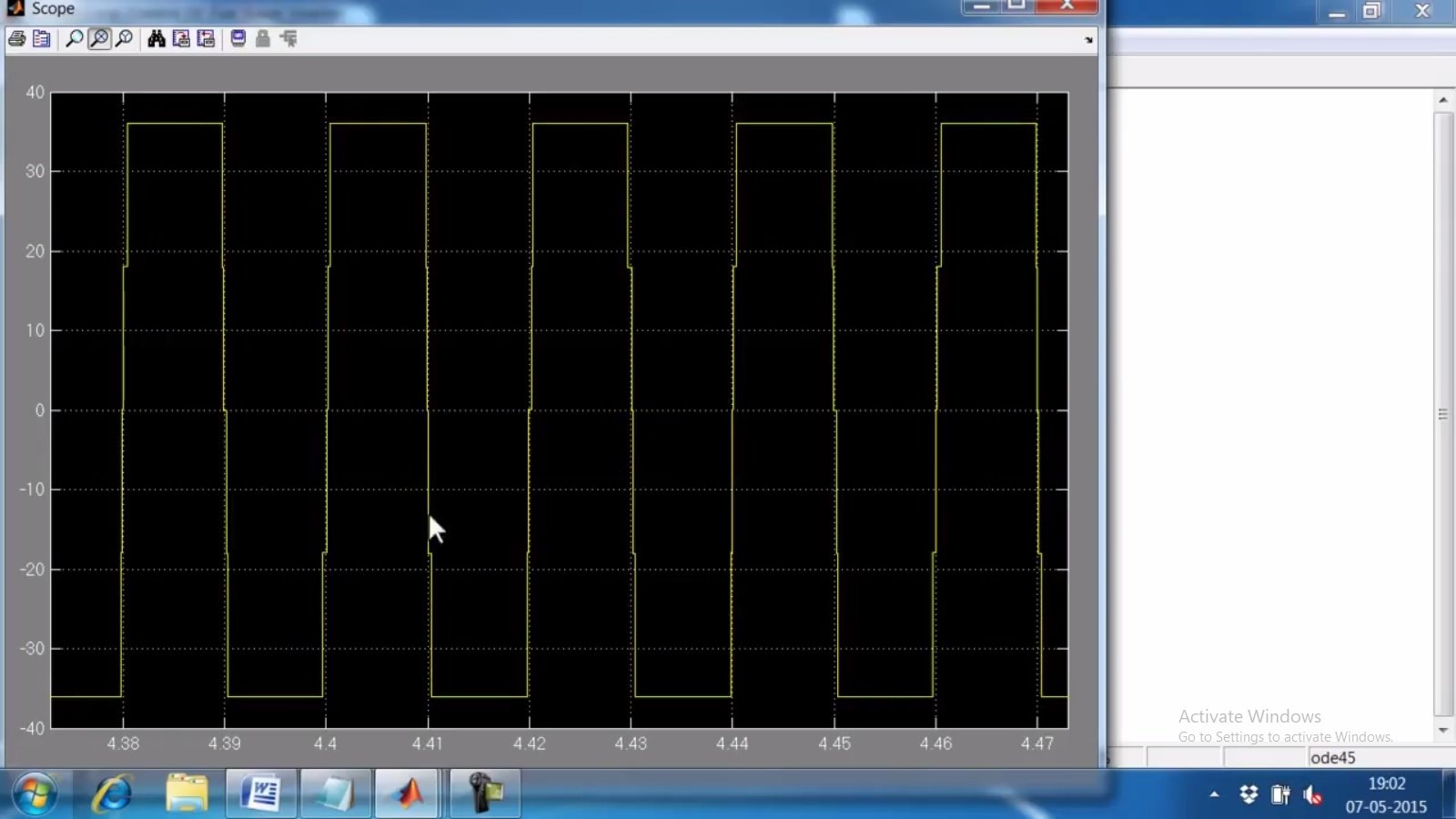
Simulation and Simulink Circuit Diagram
Conclusion
In conclusion, engineers use the bridgeless boost rectifier as an efficient power electronic converter in low voltage but high current energy harvesting applications. The bridgeless boost rectifier combines the functionality of a buck and boost converter into a single-stage AC-to-DC converter, simplifying the circuit and reducing its overall size. Designing and simulating the bridgeless boost rectifier can be done using MATLAB Simulink, allowing users to easily design the circuit by adding power electronic component blocks. The bridgeless boost rectifier operates in four modes, converting the positive and negative half cycles of AC voltages into DC voltages. Simulation and analysis can evaluate the performance and functionality of the rectifier. Overall, the bridgeless boost rectifier offers an effective solution for power electronic converters in low-voltage energy harvesting applications.
Related content:
- Simulation and Design of Three Phase Rectifier in Simulink MATLAB
- DC Motor Implementation in Simulink MATLAB
- Design Three Phase Inverter using Simulink MATLAB
- FIR Filter Design in Simulink
- Implementation of Controlled Rectifiers in Simulink MATLAB
- Full Wave Rectifier Simulation in Simulink: Tutorial 10
- How to Use Lags and Delay in Simulink: Tutorial 9


Hola Bilal
Fabricamos rectificadores de alta frecuencia hasta 2500w, con entrada monofasica y trifasica en modo de tres módulos monofasicos
Usamos puente H con mosfet
Driveamos con 2110
Nos faltaría contar con un PFC que permita controlar distorsión de corrinete y armonicos de 3 / 5 y 7° armónicas
Podríamos ver si tenes algo o bien me informas sobre el tema
Abrazo
Oscar