In this tutorial, we will explain the workings and implementation of a three phase rectifier. As we have implemented a single phase rectifier in previous tutorials, now it will be really easy to understand the workings of a three phase rectifier. At the start, we provide a brief and concise introduction to rectifiers and three phase rectifiers, along with their types. After that, we discuss the proper implementation of three phase rectifiers on MATLAB’s Simulink with explanation, along with the working of each step, the purpose of each block, and the parameter settings of each block.
Introduction to Rectifiers and Three Phase Rectifiers
In electrical and electronics engineering, we consider a rectifier to be a device that can convert an input AC voltage to a DC voltage. In most households, the main power supply is three phase Alternating Current (AC), but most of our devices, like laptops and mobile phones, use Direct voltage (DC voltage) for their charging. Hence, nowadays every house requires a three phase rectifier, and it has become very common. Now let’s talk about different types of rectifiers.
Types of Rectifiers
Depending on the output DC voltage:
- Half wave rectifier
- Full wave rectifier
Depending on the input phase voltage:
- Single phase rectifier
- Three phase rectifier
We have already discussed the former two types of rectifiers in a previous tutorial; now we will discuss the later two types.
Single phase rectifier
Rectifiers whose input voltages are single phase AC voltages around 220 V are known as single phase rectifiers. The output of such a circuit will be a high-pulsating DC voltage. We can see a waveform of single phase AC voltage in the figure below.

Three phase rectifier
Those rectifiers whose input is a three phase AC voltage around 480 V are known as three phase rectifiers. The output of three phase rectifiers is a low-pulsating DC. We can see a three phase AC voltage in the figure below.

Three Phase Rectifier Simulation in Simulink MATLAB
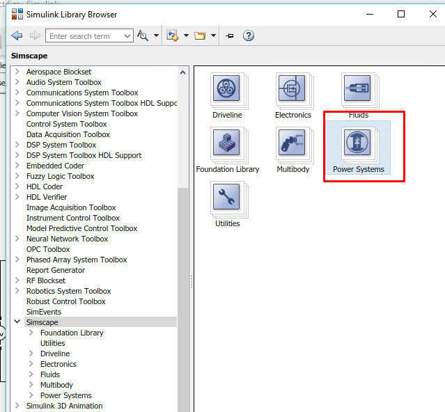
Let’s now commence our discussion of implementing the three phase inverter in MATLAB’s Simulink. Open MATLAB, then open Simulink, and create a blank model as we have been doing previously and save it for future use. At First, we open the library browser and go to the “Simscape” section in the library browser. Refer to the figure below.

Then in this block, select the power system block, as we can see in the figure below.
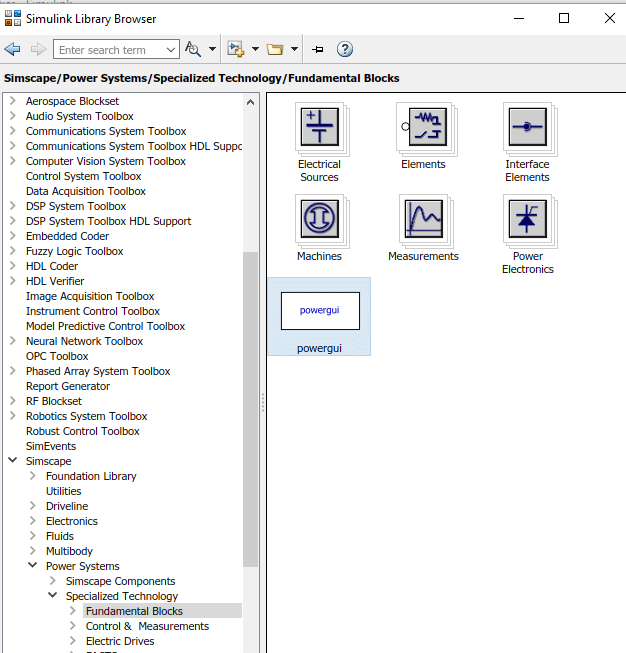
In the power system block, select the special technology block as shown in the figure below.

Fundamental Blocks
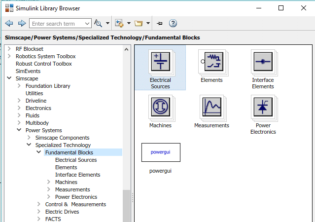
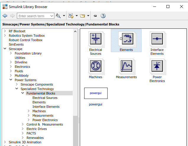
After that, select “Fundamental Blocks” in the Specialized Technology subsection, where almost all the blocks we will need in this tutorial reside. Refer to the figure below to see the fundamental blocks.

Inside that section, there will be a block with the name “powergui”. Select this block and add it to the model we have created before, as shown in the figure below.
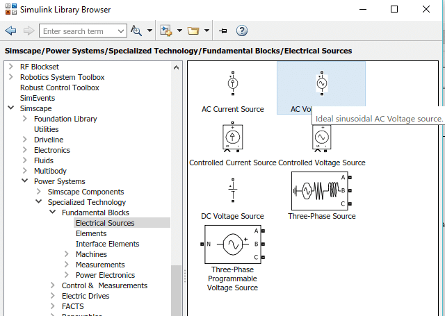
The function and use of this block are discussed in many of the previous tutorials. After that, in the fundamental block section, we will select the Electrical Sources block, as we can see in the figure below.
This block contains all the sources needed for power systems. Inside this block, select the AC voltage source and place three such sources on the model. Refer to the figure below.
Power Electronics
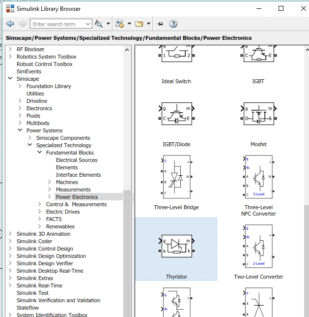
We need three sources because we want to work with three phase AC sources. Now go back to the fundamental block section and select the power electronic section, as shown in the figure below.

In this section, select the thyristor block and add six such blocks to the model, as shown in the figure below.
We need thyristors in place of diodes when we are working with a 3 phase AC source. Now in the library browser, go to the Simulink section and then select the sources block. Refer to the figure below.
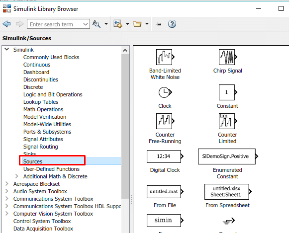
Pulse Generator
So now, from this section, select the block named pulse generator and add it to the model as shown in the figure below.

This pulse generator will be used with a pair of thyristors to turn it on and off. Hence, we will need three pulse generators (each for one pair of thyristors). Again, go to Simscape’s fundamental blocks section and select the Elements section, as we can see in the figure below.
In this section, we will need a load for the testing of our 3 phase rectifier. From this section, select the series RLC branch and add it to the model. Refer to the figure below.

Measurement Block
Also, for the measurement of voltage, go back to the fundamental blocks section and select the measurement block where all the blocks we need for measurement in power electronics or power systems are present. Refer to the figure below.

In this section, we will need a block for the measurement of voltage; hence, select the block named Voltage Measurement as shown in the figure below.

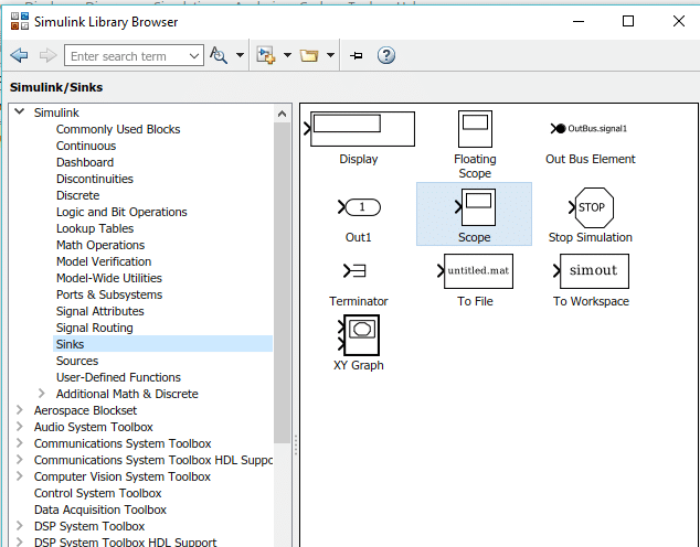
Also, we need an oscilloscope to see if the output is pure DC or not. Hence, go to the Simulink section of the library browser and select the section with the name Sinks. From this section, select the block named scope and add it to the model as shown in the figure below.
AC Voltage Parameters
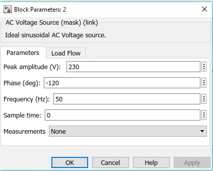
Connect the 6 thyristors in the same order as we did in the case of the three phase inverter tutorial. After this, connect three AC voltage sources to the three junctions between each pair of thyristors. Set the voltage of the source to 230V and the phase angle of the first block to 0, the second block to 120, and the third block to 240 (-120). The block parameter of the last source is shown in the figure below.
So, now we need three pulse generators to connect to each pair of thyristors, as shown in the figure below.

Hence, we connect 1st pulse generator to the thyristor pair (1, 5), 2nd to the thyristor pair (2, 6), and 3rd to the thyristor pair (3, 4), as shown in the complete block diagram. But first we look at the pulse generator block parameters; after that, we will set the phase of the 1st pulse generator to 30, the 2nd to 150, and the 3rd to 270. As we can see in the figure below.

Simulink Model
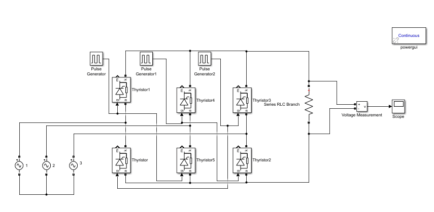
Finally, our block diagram is complete, and we can see the 3 phase rectifier in the figure below.
Simulation
At last, we run the model and double-click on the scope to see the output of the 3 phase rectifier, which should be pulsating DC as shown in the figure below.

The output of the 3 phase rectifier (as expected) is a pulsating DC. However, the ripples are way more frequent in a 3 phase rectifier as compared to a single phase rectifier. We can remove the ripples in the rectifier by using RC filters, and the output will then look like the one shown in the figure below.

Conclusion
In conclusion, this tutorial provides an in-depth overview of designing and simulating a three phase rectifier using Simulink. It covers step-by-step procedures along with explanations of an example to help us better understand the concept. You can utilize this to design more advanced and complex rectifier circuits and simulate them. Hopefully, this tutorial was helpful in expanding your knowledge of Simulink.
You may also like to read:
- BeagleBone Black Pinout, Pin Configuration and Features
- ATmega16 Microcontroller
- ESP32 SmartConfig Wi-Fi Provisioning with SmartPhone App
- SIM900A GSM Module
- ESP8266 NodeMCU MQTT Publish Subscribe BME280 Readings with Arduino IDE
- Download and Install STM32CubeIDE – Getting Started Guide
This concludes today’s article. If you face any issues or difficulties, let us know in the comment section below.
Can i get capaciotr.filter circuit with simulinkmodel
can i get passive filter design in Matlab simulink
Please explain why the pulse width is 50
Its really the most mind-blowing work I have ever seen on a microcontroller website