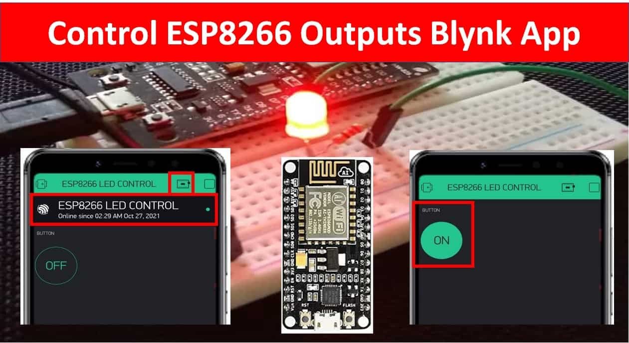
In this user guide, we will control the output of ESP8266 NodeMCU using the Blynk app and Arduino IDE. Firstly, we will set up the Blynk app library in Arduino IDE. After that, we will see how to create the LED ON/OFF button in Blynk app. Lastly, we will see an example sketch for ESP8266 NodeMCU to control LED from the Blynk app.
Previously, we controlled the ESP32 and ESP8266 module’s outputs through applications such as Telegram and Google Firebase. You can view the tutorials by accessing the links below:
Telegram ESP32 and ESP8266: Control GPIOs and LEDs using Arduino IDE
Google Firebase: Control ESP32 Outputs with Arduino IDE
This time we will show you another useful application through which we will be able to control any output connected with the ESP8266’s GPIO pins. Blynk is a free-to-use app where the user can build software to control microcontrollers such as Raspberry Pi, Arduino, and ESP8266 NodeMCU, etc. For the user, it becomes extremely interactive and easy to use this application to build IoT projects from anywhere over the internet. Only the Blynk application and a steady internet connection in your device (smartphone, laptop, tablet, etc.) are a requirement.
- We have a similar guide for ESP32 as well:
Control ESP32 Outputs using Blynk App and Arduino IDE
For this article, we will keep it simple and control an LED connected to an output GPIO of our ESP8266 module through the app in Arduino IDE. The LED will be toggled through two-way communication between the ESP8266 board and the Blynk project which you will create through the application. After that controlling any other ESP8266 module’s output will be relatively easy to follow. We can also control the buzzer, relay, motors, etc.
This article is divided into these sub-topics:
- Introduction of Blynk app
- Installing the Blynk app and creating our project
- Setting up Arduino IDE
- Controlling LED using ESP8266, Arduino IDE and Blynk application.
Blynk Application Introduction
Blynk is a highly accessible smartphone-based application available for both Android and iOS operating systems. It provides an interactive dashboard where the user can build their own IoT projects by placing components. This will as a result create a mobile app through which the user will be able to control microcontrollers connected through WIFI. You can control LEDs, relays, electric motors and many more. No internal programming is required to build your project in Blynk. You only need to drag and place your electronic components and it is as easy as that. Thus, building your IoT projects through Blynk is extremely easy and requires very little effort.
ESP8266 NodeMCU Control LED with Blynk Project Overview
We will control a single LED output through the Blynk mobile application. Our aim is to control outputs so we will use an LED for simplicity and ease of use. We will require the following components for this project.
Required Components
- ESP8266 development board
- One 5mm LED
- One 220ohm resistor
- Breadboard
- Connecting Wires
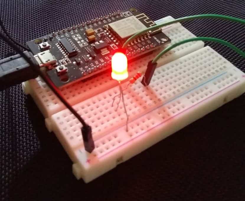
Follow the schematic diagram below to assemble your circuit.
Schematic Diagram
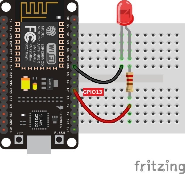
We have connected the anode pin of the LED with GPIO13 through the 220-ohm resistor. Later on, in the program code, we will configure this GPIO pin as an output pin. The cathode pin is grounded.
Setting up Blynk Application
Installing and Getting Ready
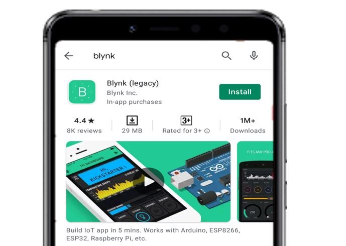
We will use an Android smartphone for this project. So go to Google Play or Apple Store (if using an iPhone).

Search for ‘Blynk’ and install the application.
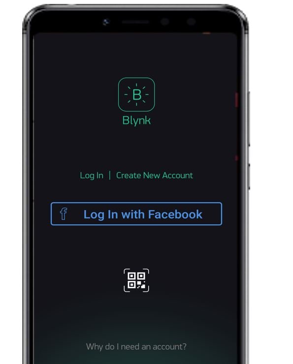
You will have to create an account to proceed further. You can also log in with your Facebook account if you possess that.
Creating Project
After you have successfully signed in the following window will appear. Click ‘New Project.’

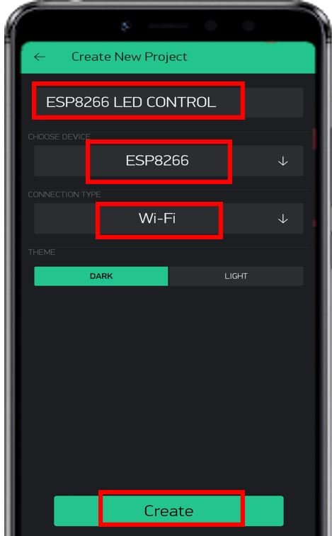
Now specify the name of your project, device and connection type. After that press the ‘Create’ button.
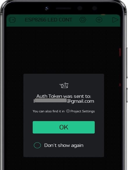
You will receive a notification regarding your Authorization token. This can be accessed from the email account you signed in with and also through Project Settings.
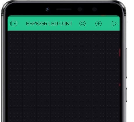
Now the Blynk canvas will open as shown below:
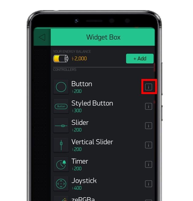
Press on the screen. The widget box will appear. Now we will build our project. Firstly, we will press the ‘Button’ widget. You can view information regarding it by pressing the icon present in the far right as highlighted below.
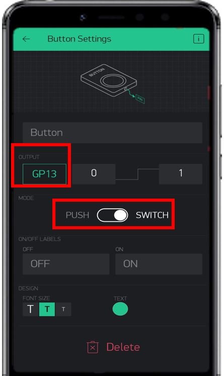
Press the button widget again on the canvas to change its parameters. In the output section, choose the GPIO pin through which your LED will be connected to the ESP8266 module. We have used GPIO13. You can use any other suitable output GPIO pin. Also, change the mode of the button to a ‘SWITCH’.
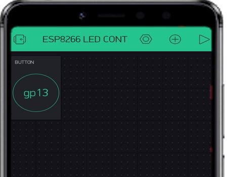
After you alter the settings of the button the canvas will look something like this:
Icons
At the top, you will find three icons. These are for Project settings, editing and play button.
Inside the play button, you can also find the stop button.
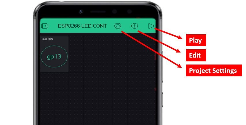
The Project Settings show you the settings you applied for your particular project and a link to the authorization key. The edit button takes you to the widget box. Lastly, the play button lets you connect your project with your microcontroller. Once you press this button you no longer will be able to add new widgets to your project unless you use the STOP button first.
As we are building a fairly simple project thus, we do not need any other widgets besides the button. Our Blynk project is ready. Let us proceed with the Arduino IDE setting.
Setting up Arduino IDE for Blynk App
We will use Arduino IDE to program our ESP8266 development board. Thus, you should have the latest version of Arduino IDE. Additionally, you also need to install the ESP8266 plugin. If your IDE does not have the plugin installed you can visit the link below:
Installing ESP8266 library in Arduino IDE
Installing Blynk Library
To use the Blynk app with our ESP8266 board, we would have to install its library.
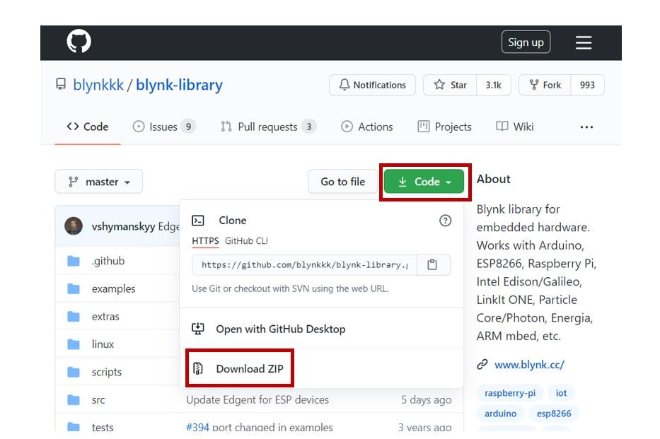
To download the library, click here. Click on ‘Code’ and then ‘Download Zip’.
You have to go to Sketch > Include Library > Add .zip Library inside the IDE to add the library as well. After installation of the library, restart your IDE.
Arduino Sketch (Connecting ESP8266 with Blynk)
Open your Arduino IDE and go to File > New to open a new file. Copy the code given below in that file. You need to enter your network credentials. Additionally, you also have to provide your Authorization key which you obtained from the Blynk app.
#define BLYNK_PRINT Serial
#include <ESP8266WiFi.h>
#include <WiFiClient.h>
#include <BlynkSimpleEsp8266.h>

int led_gpio = 13;

#define Authorization_key "H4x28k5X4b9IBnmbP1n5iA51BZ******"
#define SSID "Your_SSID"       // replace with your SSID
#define Password "Your_Password"           //replace with your password

void setup() {
  pinMode(led_gpio, OUTPUT);
  Serial.begin(115200);
  delay(10);
  WiFi.begin(SSID, Password);
  while (WiFi.status() != WL_CONNECTED) {
  delay(500);
  Serial.print(".");
  }
  Blynk.begin(Authorization_key,SSID,Password);
}
void loop(){
    Blynk.run();
}
How the Code Works?
Including Libraries
Firstly, we will include the necessary libraries required for this project. ESP8266WiFi.h will help in establishing the connection between the ESP8266 module to a wireless network. We will also include the libraries, for the Blynk application functionality.
#define BLYNK_PRINT Serial
#include <ESP8266WiFi.h>
#include <WiFiClient.h>
#include <BlynkSimpleEsp8266.h>
Output Variable
Then, we will define the variable of data type int called ‘led_gpio’. It will save the GPIO pin through which we will connect our LED. We are using GPIO13 in our case. Make sure to enter the same GPIO pin in the program code which you saved when creating the button in the Blynk app. Thus, we will control this pin through the app.
int led_gpio = 13;Defining Authorization key
Thirdly, we will define the authorization key which was emailed to us through Blynk in our account through which we logged in it. Keep this key safe with you for security concerns.
#define Authorization_key "H4x28k5X4b9IBnmbP1n5iA51BZ******" Defining Network credentials
Next, we will define the network credentials. One for the SSID and the other for the password. These will be our network credentials which will be used to connect to our wireless network. Replace both of them with your credentials to ensure a successful connection.
#define SSID "Write_your_SSID_here"
#define Password "Write_your_password_here"
Setup() function
Inside the setup() function, we will open a serial connection at a baud rate of 115200.
Serial.begin(115200);By using the pinMode() function, the ‘led_gpio’ variable (GPIO13) will be passed as a parameter inside the function. This will configure the pin as an output.
pinMode(led_gpio, OUTPUT); The following section of code will connect our ESP8266 board with the local network whose network credentials we already specified above. We will use the WiFi.begin() function. The arguments will be the SSID and the password which we defined earlier in the code.
WiFi.begin(SSID, Password);
  while (WiFi.status() != WL_CONNECTED) {
  delay(500);
  Serial.print(".");
  }
Now, we will connect our ESP8266 module with the Blynk app by using the Blynk.begin() function. It takes in three parameters. The first is the authorization key. The second is the SSID and the third parameter is the password of the WIFI. All three of these were defined earlier on in the program code. Through correct credentials, a successful connection will be made.
Blynk.begin(Authorization_key,SSID,Password);loop() function
Inside the loop function, we will use the Blynk.run() command to keep the connection running.
Blynk.run();Demonstration
Choose the correct board and COM port before uploading your code to the board.
Go to Tools > Board and select NodeMCU 1.0

Next, go to Tools > Port and select the appropriate port through which your board is connected.
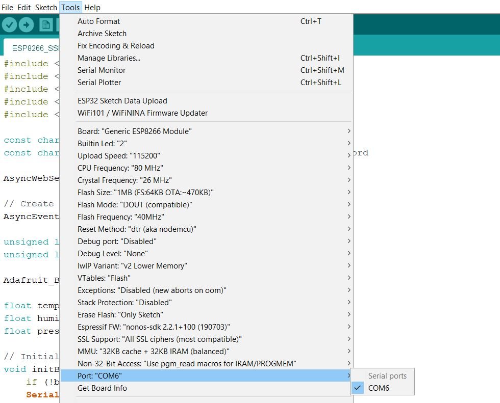
Click on the upload button to upload the code to your ESP8266 development board.
After you have uploaded your code to the development board, press its RST button.

In your Arduino IDE, open up the serial monitor and you will be able to see the status of your WIFI connection. You will receive different messages as shown below.

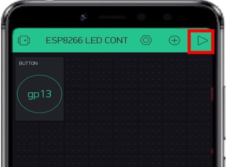
When you receive the ‘ready’ message on the serial monitor, open your Blynk application. Open the project you created and press the ‘play’ button.
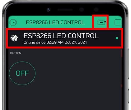
Click the microcontroller icon at the top. You will receive a notification about the connection being established with your ESP8266 board.
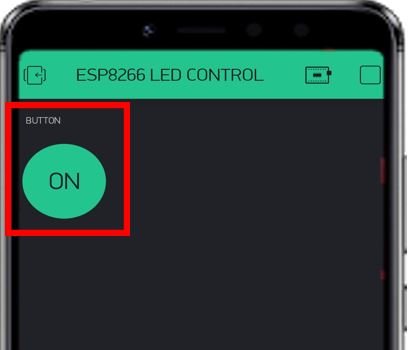
Now, touch the Button widget to toggle the LED. By pressing ON/OFF, simultaneously the LED connected to GPIO13 will turn ON/OFF as well. To disrupt the connection, press the stop button.
Conclusion
In conclusion, we were able to control our ESP8266 module’s output by creating a mobile app in Blynk. We controlled an LED connected to a pin configured as an output. Similarly, you can use any other output GPIOs easily and control it through the app.
You may like to read:
- ESP8266 Send Emails (Plain text, HTML, and Attachments) through SMTP Server
- ESP8266 NodeMCU HTTP POST using Arduino IDE (ThingSpeak and IFTTT)
- IoT Based Analog and Digital Clock using OLED and ESP32/ESP8266
- ESP8266 NodeMCU PWM Slider Web Server – Control LED Brightness
- ESP-MESH Getting Started using painlessMesh Library and ESP32/ESP8266
- ESP8266 IoT Motion Detection Web Server with Email Alert
Can i get the full code for controlling LEDs through blynk app and nodemcu esp8266?