STM32CubeIDE is an Integrated Development Environment (IDE) developed by STMicroelectronics that provides a comprehensive and user-friendly platform for developing and debugging STM32 microcontroller applications. It combines code editing, compilation, debugging, and hardware configuration tools into a single application, making it an ideal solution for embedded systems developers. Built on the Eclipse/CDT framework, STM32CubeIDE integrates STM32CubeMX for peripheral configuration and code generation, as well as GDB-based debugging. If you are new to STM32CubeIDE, you may be wondering how to get started with downloading and installing this software. In this article, we will provide a step-by-step guide to help you download, install, and create your first project in STM32CubeIDE. Whether you are a beginner or an experienced developer, this guide will help you get up and running quickly.
Downloading STM32CubeIDE
In this section, we will show you how to download STM32CubeIDE for Windows, Linux, and macOS.
Go to the following link:
Click the ‘Get latest’ button according to your operating system. In this tutorial, we are using Windows.

A registration form will open up. You will have to create an account by providing the required information and then clicking the ‘Download’ button. If you already have an account on my.st.com, you can use that to log in as well.
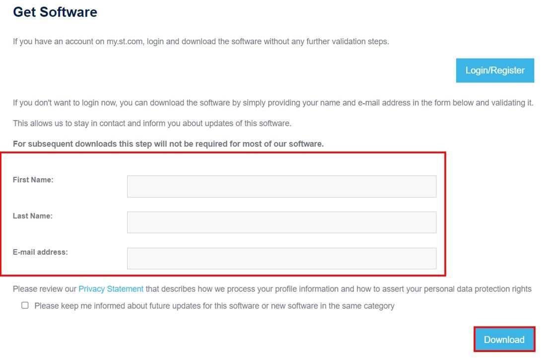
After specifying your personal information and clicking the download button, your registration will be complete. A validation link will be sent to the email address you used for registration. Once you validate your email address, the download will automatically start. The email will be sent by STMicroelectronics.
Installing STM32CubeIDE
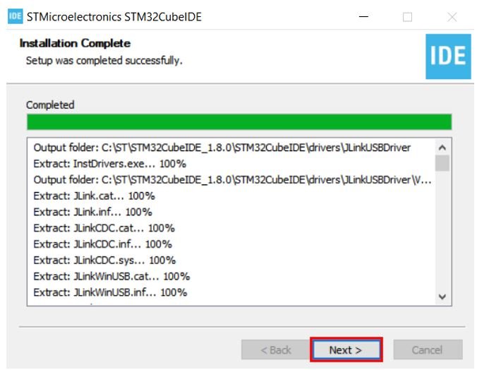
Once the download is complete, extract the .zip file and run the installer. You will be prompted to accept the license agreement. After accepting the agreement and choosing the desired installation location, the installation process will begin. It may take several minutes for STM32CubeIDE to install completely, depending on your system.
After the installation is complete, click ‘Next’.
When the installation is finished, click ‘Finish’ to close the setup wizard. A shortcut to STM32CubeIDE will now be created on your desktop.

Getting Started with STM32CubeIDE
In this section, we will get started with STM32CubeIDE by creating our first project. For demonstration purposes, we will learn how to use GPIO pins of the STM32 Blue Pill as digital output pins and configure them in STM32CubeIDE.
We will create an LED blinking example using the STM32 Blue Pill. This board has an onboard LED connected to GPIO pin PC13.
Let’s see how to write your first program for the STM32 Blue Pill in STM32CubeIDE.
Write Your First STM32 Program in STM32CubeIDE
Now that we have installed the STM32CubeIDE application, let us learn how to use it to program our STM32 boards.
Open the application. You will be asked to specify the directory for the workspace. You can specify the directory and also tick the checkbox below to set it as the default workspace. Next, click ‘Launch’ to start the application.

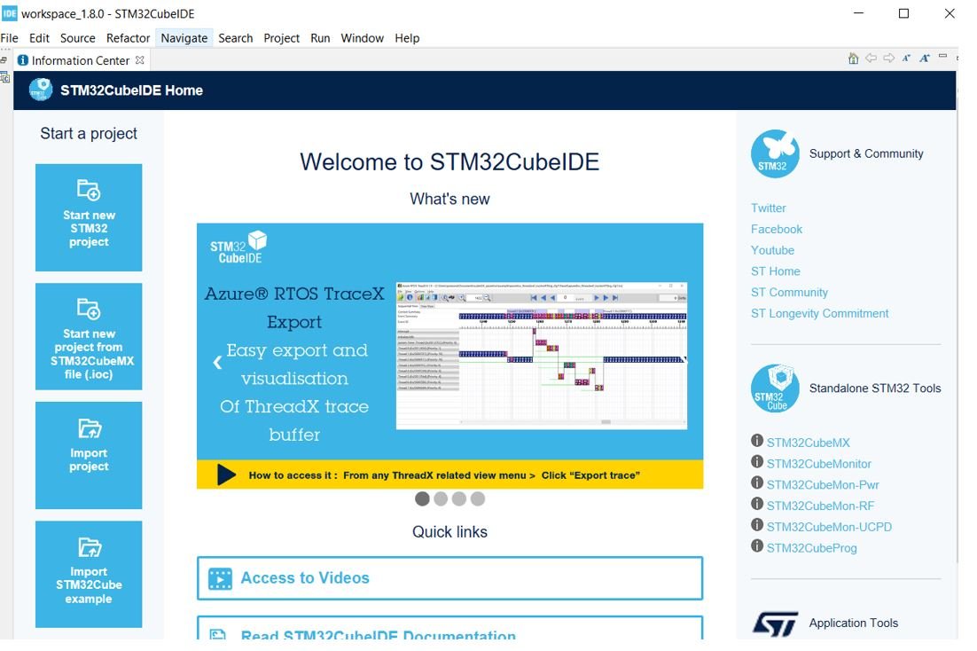
The STM32CubeIDE workspace will open.
Creating a Project in STM32CubeIDE
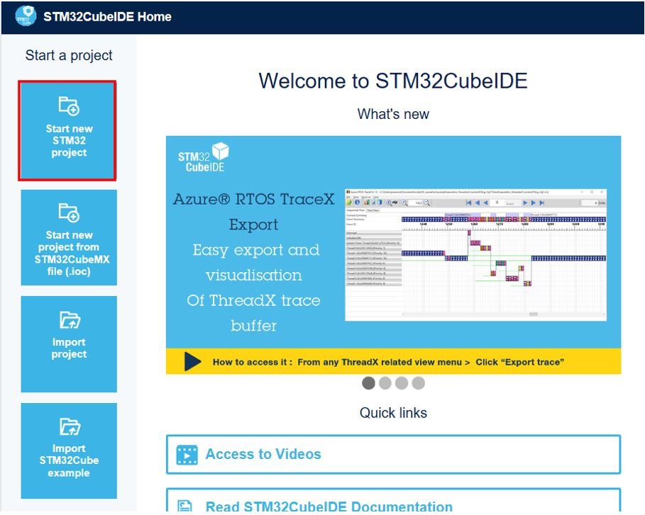
Now click ‘Start new STM32 project’.
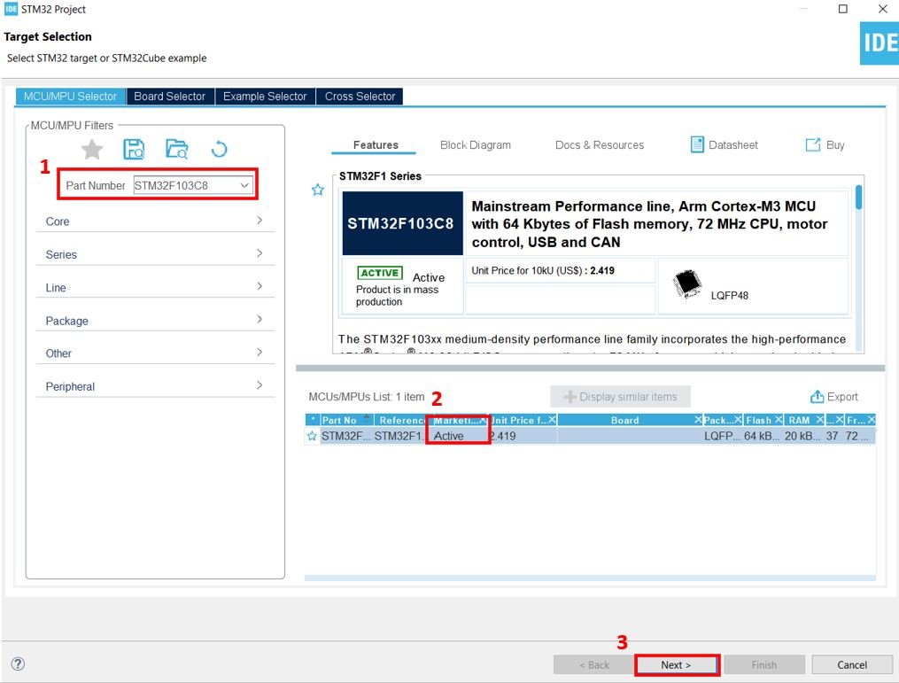
The Target Selection window will open.

Select your device from the ‘Part Number’ field. We are working with ‘STM32F103C8’. Then click any column entry and click the ‘Next’ button to proceed further.
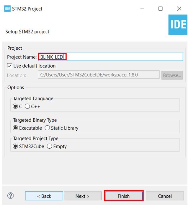
Give your project a name. Since we are going to blink the onboard LED of our STM32 board, we have named our project ‘BLINK_LED.’ Then click ‘Finish.’
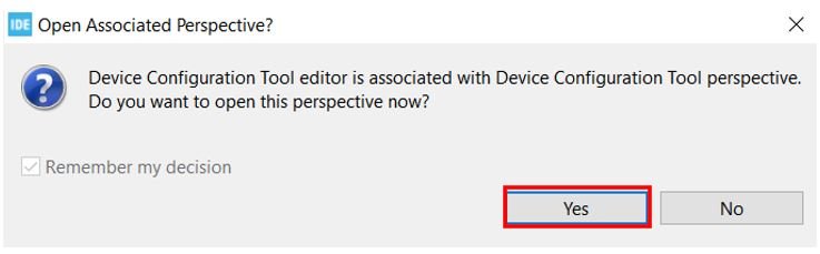
You will be asked to open the associated perspective. Click ‘Yes’.
Device Configuration Tool
The Device Configuration Tool window will now open. This is where you can set pin-specific functions for your microcontroller.
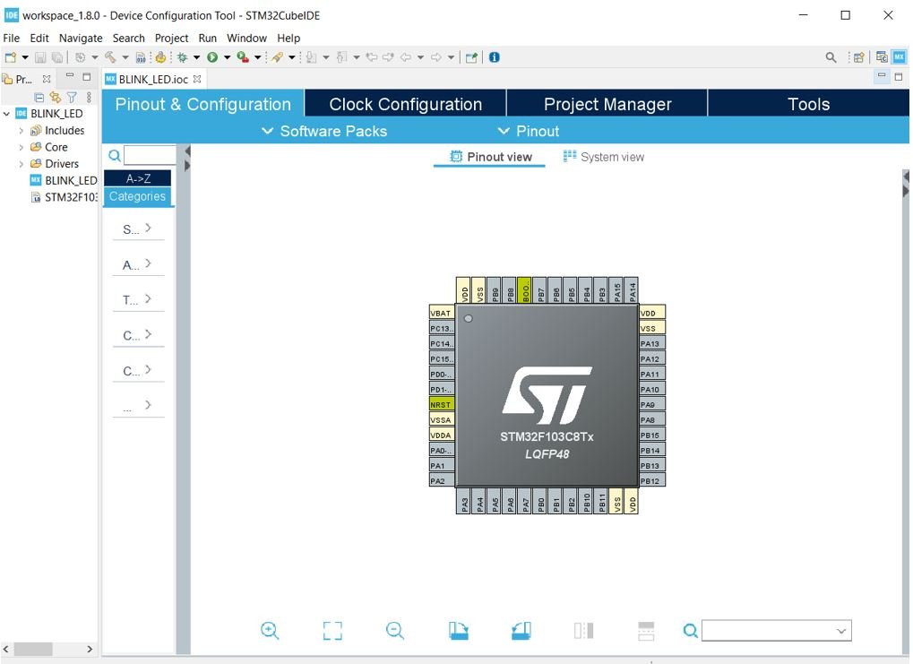
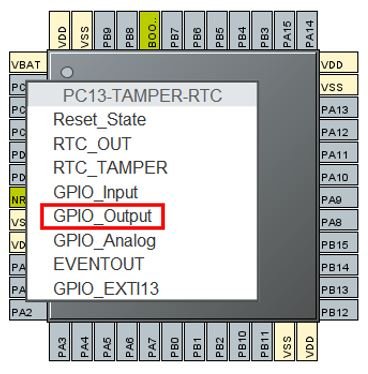
The STM32 Blue Pill has an onboard LED connected to PC13. Click on the PC13 pin in the Device Configuration Tool.

A list of functions associated with the pin will appear. Select ‘GPIO_Output’ to set this pin as a digital output.
This is how the configuration will look. You can see that GPIO_Output has been assigned to PC13.
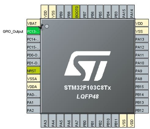
Additionally, there are more configuration options available for each pin. Go to System Core > GPIO > PC13 to open the pin configuration panel. Here, we have given the pin a user label of ‘LED.’ You can see in the Device Configuration Tool that PC13 now has the label ‘LED.’
Apart from the label, there are several other options to choose from, including GPIO output level, mode, pull-up/pull-down state, and maximum output speed.

Now save the file by pressing Ctrl + S. The following window will appear. Click ‘Yes.’ This will generate the initialization code based on your pin configuration.

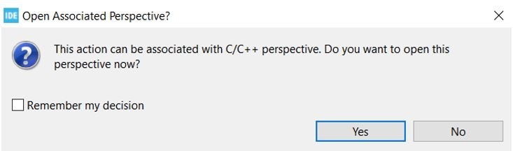
Another window will appear asking if you want to open the C/C++ perspective. Click ‘Yes.’
Code
The code editor will now open. On the right side, you can view the Outline of the code. This appeared because we opened the code with the C/C++ perspective.
In the center, you can view the main.c file, and on the left, you can view the Project Explorer.
If you want to go back to the Device Configuration Tool, click the BLINK_LED.ioc tab.

STM32 Blue Pill LED Blinking Code
Now let us modify the main.c file for our BLINK_LED project. Our goal is to blink the onboard LED continuously with a delay between each toggle.
First, inside the main() function, go to the while(1) loop and insert the following lines of code. These will make the onboard LED blink indefinitely.
  while (1)
  {
    HAL_GPIO_WritePin(LED_GPIO_Port, LED_Pin, GPIO_PIN_RESET);
    delay(500000);
    HAL_GPIO_WritePin(LED_GPIO_Port, LED_Pin, GPIO_PIN_SET);
    delay(500000);
  }
The HAL_GPIO_WritePin() function takes three parameters: the GPIO port, the GPIO pin, and the pin state. This function sets the specified pin either HIGH or LOW.
Notice that we labeled the onboard LED as ‘LED.’ Therefore, we use LED_GPIO_Port and LED_Pin as the first two parameters. If you used a different label, replace ‘LED’ with your own pin label in the code.
When the third parameter is set to GPIO_PIN_RESET, it drives the pin LOW (turning the LED on, since the onboard LED is active-low). When the third parameter is set to GPIO_PIN_SET, it drives the pin HIGH (turning the LED off).
Between these two function calls, we use a custom delay() function to create a visible blinking effect. Since this is not a built-in function, we need to define it ourselves. Insert the following definition of the delay() function after Error_Handler().
void delay (int x)
{
  volatile int i,j;
  for (i=0 ; i < x ; i++)
  {
     j++;
  }
  return;
}
Additionally, add the function prototype of delay() along with the other private function prototypes as shown below:
/* Private function prototypes -----------------------------------------------*/
void SystemClock_Config(void);
static void MX_GPIO_Init(void);
void delay (int x);
Save the main.c file after making these modifications. Now we are ready to build our project.
Note: Alternatively, you can use the built-in HAL_Delay() function (which accepts milliseconds) instead of creating a custom delay function. For example, HAL_Delay(500) will create a 500-millisecond delay.
Building the Project in STM32CubeIDE
To build the BLINK_LED project, press Ctrl + B or go to Project > Build All.

The project will start building. After a few moments, the build will complete successfully if there are no errors in your code.

Connecting the ST-Link Programmer with STM32
Now that we have successfully built the BLINK_LED project, let us upload the code to our STM32 board. To do this, we need to connect the Blue Pill STM32 to an ST-Link programmer. We will be using the ST-Link V2.

The ST-Link V2 provides a Serial Wire Debug (SWD) interface between your computer and the STM32 board. It has 10 pins, but we only need four of them: Pin 2 (SWDIO), Pin 6 (SWCLK), Pin 4 (GND), and Pin 8 (3.3V). SWDIO is the data input/output pin and SWCLK is the clock pin. Refer to the pin configuration printed on the ST-Link V2 to identify each pin.
Follow the table below to connect both devices correctly.
| STM32 Blue Pill | ST-LINK V2 |
|---|---|
| VCC 3.3V pin | Pin 8 (3.3V) |
| SWDIO pin | Pin 2 (SWDIO) |
| SWCLK pin | Pin 6 (SWCLK) |
| GND pin | Pin 4 (GND) |

Additionally, move the BOOT0 jumper to the '1' position (to the right) to put the microcontroller into programming mode.

Now connect the ST-Link V2 to your computer via the USB port. Both devices will power on.

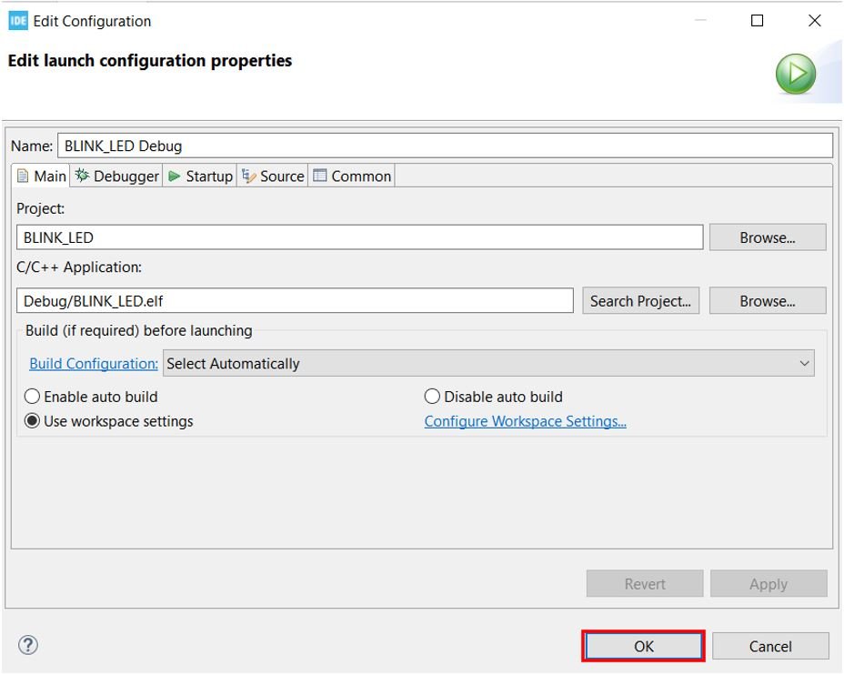
Next, press the RUN button in the IDE. The 'Edit Configuration' window will open. Click 'OK'.
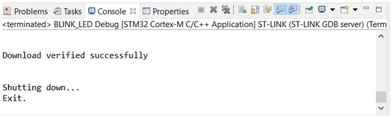
After a few moments, the code will be successfully flashed to the STM32 board. You can verify this by checking the Console terminal for a success message.
If the LED does not start blinking immediately, press the RESET button on your STM32 board.
Finally, to bring the Blue Pill back to normal run mode, move the BOOT0 jumper back to its original position (to the left, '0' position). After doing that, press the RESET button on the board. The onboard LED will start blinking immediately.
Troubleshooting Tips
If you encounter issues during the setup or programming process, here are some common solutions:
ST-Link not detected: Make sure the ST-Link V2 drivers are installed on your computer. You can download the ST-Link USB drivers from the STMicroelectronics website. On Windows, you may also need to install the drivers manually from the STM32CubeIDE installation folder under the 'drivers' directory.
Build errors: Double-check that the delay() function definition and prototype are placed in the correct locations within the main.c file. The function prototype should be placed with the other private function prototypes, and the definition should be placed after the Error_Handler() function.
Code not running after upload: Ensure that you have moved the BOOT0 jumper back to its original position and pressed the RESET button after uploading the code.
LED stays on or off: The onboard LED on the STM32 Blue Pill is active-low, meaning it turns on when the pin is driven LOW (GPIO_PIN_RESET) and turns off when driven HIGH (GPIO_PIN_SET). Verify that your code uses the correct logic.