In this tutorial, we will learn to use or interface HC-SR04 ultrasonic sensor with STM32 Nucleo and program it using STM32CubeIDE and HAL libraries. At first, we will take a look at the ultrasonic sensor, then interface it with our STM32 Nucleo and program it for contactless distance measurement using STM32CubeIDE. For demonstration, we will connect an SSD1306 OLED with the STM32 Nucleo to view the distance measurements on the OLED.
As discussed earlier, we will be using STM32CubeIDE, therefore, you should have the latest version installed on your system. You can follow this guide to install it:
HC-SR04 Ultrasonic Sensor Introduction
The HC-SR04 ultrasonic sensor uses sonar energy to measure distance to an object ranging from 2-400 cm with an accuracy of 0.3cm. It consists of both the transmitter and the receiver modules. The transmitter module is used to convert the electrical signal into a 40KHz burst of 8 sonar wave pulses. On the other hand, the ultrasonic receiver circuit listens to the ultrasonic waves produced by the transmitter circuit.
To interface the HC-SR04 ultrasonic sensor with STM32 Nucleo, we should know the functionality of each pin of the ultrasonic sensor. By knowing the functionality of the input and output pins, we will be able to identify which pins of Nucleo should be used to interface with HC-SR04.
HC-SR04 Pinout
The figure given below shows the pin configuration of an ultrasonic sensor. It consists of four pins namely; VCC, Ground, Trigger, and Echo pin.
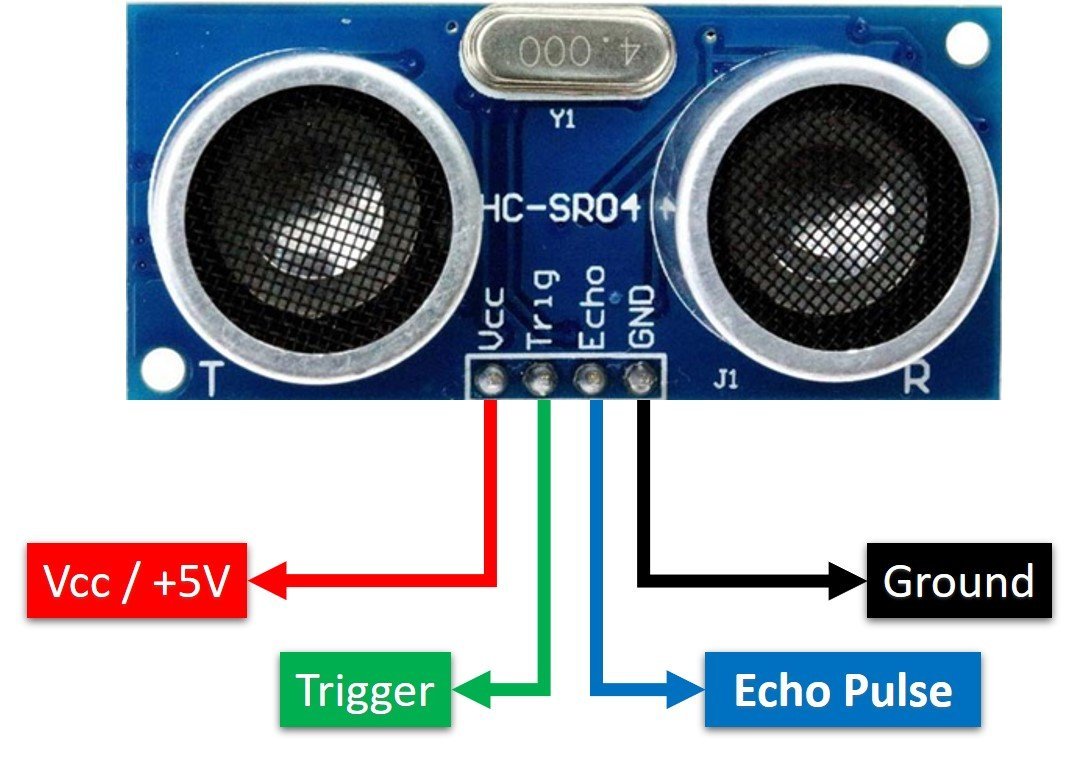
Vcc and Ground are used to power sensor. We should supply 5 volts to the Vcc pin and connect the GND pin with the ground terminal of the power supply.
Trigger: It is an input pin. A trigger pin is used to initiate the ultrasonic sensor to start distance measurement or distance ranging. When users want to get distance measurements from the sensor, we apply a 10µs pulse to this pin.
Echo: This is a pulse output pin. The echo pin produces a pulse as an output. The width of pulse or on-time of the pulse depends on the distance between the ultrasonic sensor and the obstacle which is placed in front of the HC-SR04 sensor. In idle conditions, this pin remains at an active low level.
Further details on ultrasonic sensor working are provided in the next section.
Working of HC-SR04 Sensor
HC-SR04 ultrasonic sensor measures distance by using inaudible ultrasonic sound waves of 40KHz frequency. Like sound waves, ultrasonic waves travel through the air and if there is any obstacle in front of them, they reflect according to their angle of incidence. Moreover, if an object is placed parallel to an ultrasonic transmitter, ultrasonic waves reflect exactly at an angle of 180 degrees. Therefore, for distance measurement with HC-SR05 sensor, we place the object under test, exactly in a parallel position with an ultrasonic sensor as shown in the figure below.
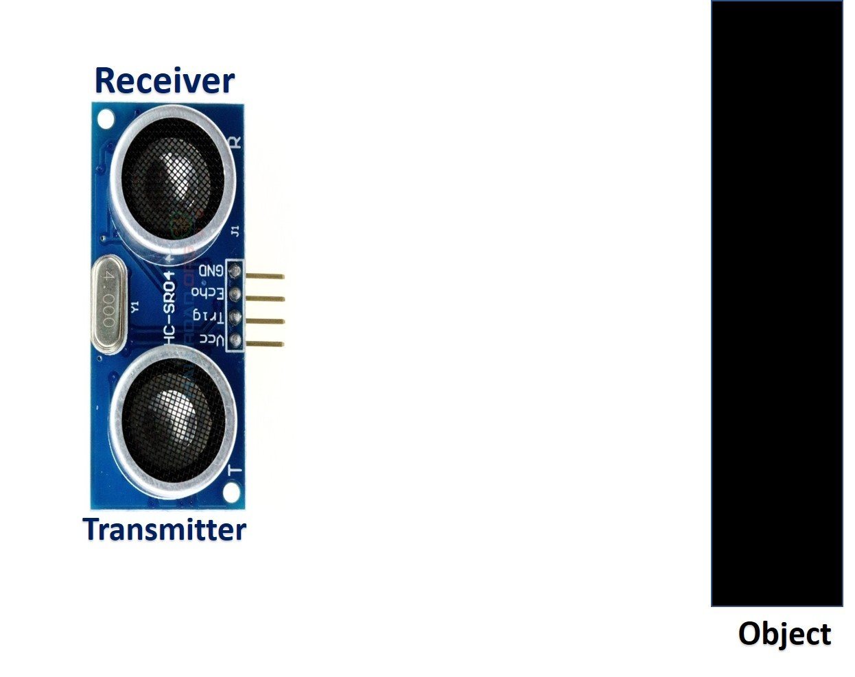
HC-SR05 ultrasonic sensor consists of two basic modules such as ultrasonic transmitter and ultrasonic receiver module. The transmitter circuit converts an electrical signal into a 40KHz burst of 8 sonar wave pulses. The input electrical signal to the transmitter circuit is 10µs pulse input to the trigger pin of the HC-SR04 sensor. As we mentioned earlier, we apply this trigger input signal through STM32 Nucleo. On the other hand, the ultrasonic receiver circuit listens to these ultrasonic waves which are produced by the transmitter circuit.
Measure HC-SR04 Echo Pulse Time with STM32 Nucleo
- To start ranging with HC-SR04, first, we apply 10µs pulse to the trigger pin of the HC-SR04 sensor from STM32 Nucleo digital output pin.
- As soon as the 10µs input trigger signal becomes active low, the transmitter circuit produces a burst of 8 ultrasonic sonar pulses. At the same time, the echo pin also makes a transition from a logic low level to a logic high level.
- Using the HAL libraries, we save the TIM Counter Register value (val1) on runtime when the echo pin goes high.
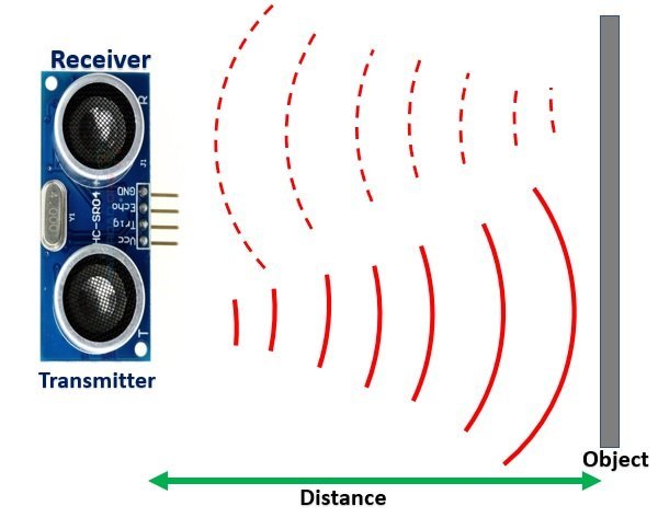
- These waves travel through the air and if there is any object placed in parallel to the sensor, these waves reflect back after a collision with the object.
- As soon as the ultrasonic waves received by the receiver circuit after striking with an object, the echo pin goes low. At that point the TIM Counter Register value (val2) on runtime is saved as well.
- Both these values will be used to determine the distance to an object.
In short, by measuring the on-time of the echo output pulse signal, we can measure the distance. The following figure illustrates the echo output signal with respect input trigger signal and 8 sonar pulses.
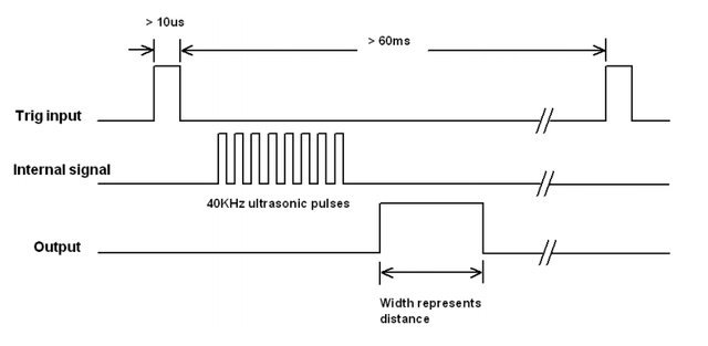
The duration for which the echo output signal remains high depends on the distance between the ultrasonic sensor and the object which we place in front of the sensor. Higher is the distance, the higher the time sonar waves will take to reach back to the ultrasonic receiver circuit. Because ultrasonic waves travel through the air with the speed of sound and speed remains constant.
Interface HC-SR04 Ultrasonic sensor with STM32 Nucleo and OLED
We will need the following components for this project.
- STM32 Nucleo board
- HC-SR04
- SSD1306 OLED
- Breadboard
- Connecting Wires
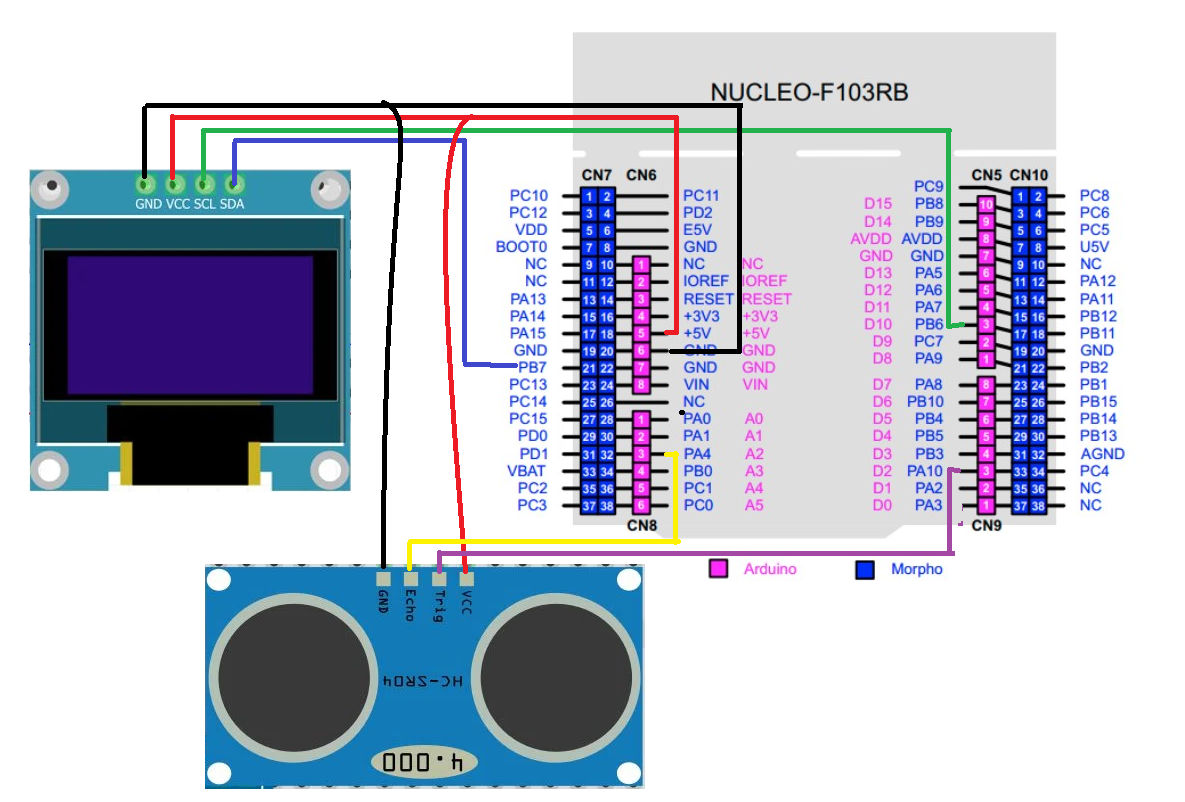
The connections between the ultrasonic sensor and Nucleo can be seen below.
| HC-SR04 Sensor | STM32 Nucleo |
|---|---|
| VCC | 5V |
| Trigger | PA10 |
| Echo | PA4 |
| GND | GND |
The connections between the OLED and Nucleo can be seen below.
| STM32 Nucleo | SSD1306 OLED Display |
|---|---|
| 5V | VCC |
| PB7 | SDA |
| PB6 | SCL |
| GND | GND |
Connect the HC-SR04 sensor and OLED with STM32 Nucleo as shown in the schematic diagram below. We are using the same connections as specified in the tables above.

Ultrasonic Sensor and OLED with STM32 Nucleo Program
We will use STM32CubeIDE to program our STM32 board. Open the IDE and head over to a new project.
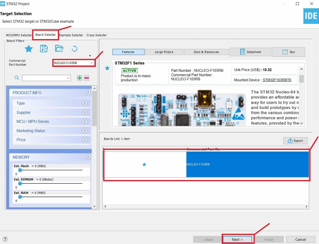
Then for the target selection, specify the STM32 Nucleo board number. After that click on any column as shown in the picture below. Then click the ‘Next’ button.
Specify the name of your project then click ‘Finish’ to complete the setup of your project.
Now go to System Core > RCC then select ‘Crystal/Ceramic Resonator’ in from the High Speed Clock feature.

Now we have enabled the RCC external clock source.
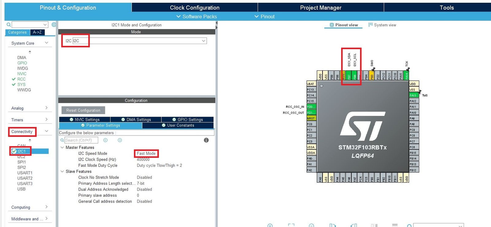
Now head over to Connectivity > I2C1. Select the I2C mode as ‘I2C.’ Then go to ‘Parameter Settings’ and set the I2C speed mode as ‘Fast Mode.’ This is necessary for the SSD1306 OLED.
Now head over to Timers > TIM1 and select the Clock Source as ‘Internal Clock.’ Then click the Parameter Settings and set the Prescaler as 71.

Moreover, configure PA10 as GPIO_Output and PA4 as GPIO_Input. These pins will be connected with the Trigger and Echo pins of the HC-SR04 sensor respectively.

Clock Configuration
Next, go to the Clock Configuration found at the top. This will open the following window. Here we will select the clock frequency.
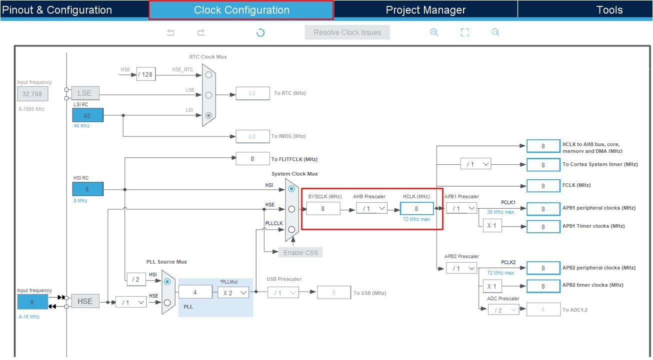
You can specify your system clock. We will set it as 72 MHz. These are the configurations we have set:

Now we will save our file. Press Ctrl + S. The following window will appear. Click ‘Yes.’ This will generate a template code for you.

Another window will appear that will ask if you want to open the perspective. Click ‘Yes.’

STM32 OLED Library
As we are working with an SSD1306 OLED with our STM32 Nucleo, we will require the ssd1306.h and fonts.h libraries. These libraries will be used to access different functions that will enable us to display texts and numbers on the OLED in various ways.
ssd1306.h
Go to Core > Inc and create a new file called ‘ssd1306.h‘ Copy the following code from this link and save it to this file.
In ssd1306.h file, remove #include “i2c.h” (line 49) and add extern I2C_HandleTypeDef hi2c1;
fonts.h
Go to Core > Inc and create a new file called ‘fonts.h‘ Copy the following code from this link and save it to this file.
ssd1306.c
Similarly, head over to Core > Src and create a new file called ‘ssd1306.c‘ Copy the following code from this link and save it to this file.
fonts.c
Head over to Core > Src and create a new file called ‘fonts.c‘ Copy the following code from this link and save it to this file.
STM32 Nucleo Ultrasonic Sensor with OLED Code
Now let us look at our main.c file that was generated. Inside the main.c file, make sure the following code is part of your script by including the lines of code given below.
#include "main.h"

#include "fonts.h"
#include "ssd1306.h"
#include "stdio.h"

I2C_HandleTypeDef hi2c1;

TIM_HandleTypeDef htim1;

#define TRIG_PIN GPIO_PIN_10
#define TRIG_PORT GPIOA
#define ECHO_PIN GPIO_PIN_4
#define ECHO_PORT GPIOA

uint32_t pMillis;
uint32_t val1 = 0;
uint32_t val2 = 0;
uint16_t distance  = 0;
char string[15];

void SystemClock_Config(void);
static void MX_GPIO_Init(void);
static void MX_I2C1_Init(void);
static void MX_TIM1_Init(void);

int main(void)
{

  /* Reset of all peripherals, Initializes the Flash interface and the Systick. */
  HAL_Init();

  /* Configure the system clock */
  SystemClock_Config();

  /* Initialize all configured peripherals */
  MX_GPIO_Init();
  MX_I2C1_Init();
  MX_TIM1_Init();

  HAL_TIM_Base_Start(&htim1);
  HAL_GPIO_WritePin(TRIG_PORT, TRIG_PIN, GPIO_PIN_RESET);
  SSD1306_Init();

  while (1)
  {
	  HAL_GPIO_WritePin(TRIG_PORT, TRIG_PIN, GPIO_PIN_SET);
	  __HAL_TIM_SET_COUNTER(&htim1, 0);
	   while (__HAL_TIM_GET_COUNTER (&htim1) < 10);  // wait for 10 us
	   HAL_GPIO_WritePin(TRIG_PORT, TRIG_PIN, GPIO_PIN_RESET);

	   pMillis = HAL_GetTick();
	   while (!(HAL_GPIO_ReadPin (ECHO_PORT, ECHO_PIN)) && pMillis + 10 >  HAL_GetTick());
	   val1 = __HAL_TIM_GET_COUNTER (&htim1);

	   pMillis = HAL_GetTick();
	   while ((HAL_GPIO_ReadPin (ECHO_PORT, ECHO_PIN)) && pMillis + 50 > HAL_GetTick());
	   val2 = __HAL_TIM_GET_COUNTER (&htim1);

	   distance = (val2-val1)* 0.034/2;

	   SSD1306_GotoXY (20, 0);
	   SSD1306_Puts ("Distance", &Font_11x18, 1);
	   sprintf(string,"%d    ", distance);
	   SSD1306_GotoXY (55, 30);
	   SSD1306_Puts (string, &Font_16x26, 1);
	   SSD1306_UpdateScreen();
	   HAL_Delay(50);
  }

}
How Code Works?
We start off by including fonts.h and ssd1306.h libraries for the OLED functionality.
#include "fonts.h"
#include "ssd1306.h"
#include "stdio.h"
Next, we define the GPIO pins that will be used to connect with the trigger and echo pins of the ultrasonic sensor. We have configured GPIO pins 3 and 4 to connect with Trigger and Echo pins respectively. Moreover, the selected port is GPIOA for both of these pins. We setup PA3 as GPIO_Output and PA4 as GPIO_Input in the configuration.
#define TRIG_PIN GPIO_PIN_10
#define TRIG_PORT GPIOA
#define ECHO_PIN GPIO_PIN_4
#define ECHO_PORT GPIOA
Create some variables that will be used later on in the code to store values.
uint32_t pMillis;
uint32_t val1 = 0;
uint32_t val2 = 0;
uint16_t distance  = 0;
char string[15];
main()
Inside the main function, first all the peripherals are initialized, system clock is configured and all the configured peripherals are initialized.
  HAL_Init();
  SystemClock_Config();
  MX_GPIO_Init();
  MX_I2C1_Init();
  MX_TIM1_Init();
After that we call HAL_TIM_Base_Start() to start the TIM base generation. This function takes in a single parameter which is the TIM_HandleTypeDef structure that holds the configuration parameters for TIM module.
HAL_TIM_Base_Start(&htim1);Set the trigger GPIO pin to a LOW state by calling HAL_GPIO_WritePin. This function takes in three parameters which are the selected GPIO peripheral, GPIO port bit and the pin state respectively.
HAL_GPIO_WritePin(TRIG_PORT, TRIG_PIN, GPIO_PIN_RESET);Next, we initialize the OLED. We use the SSD1306_Init() function for initialization.
SSD1306_Init();Inside the infinite while loop, we first set the trigger pin to a HIGH state through HAL_GPIO_WritePin() function. After that we set the timer counter register value on runtime as ‘0.’ It continues to run while the timer counter register value which is the single parameter of this function, remains less than the 10us. After the 10us are over, the trigger pin is set to a LOW state. Next we wait for the echo pin to go to a high state and capture the TIM Counter Register value and save it in the variable ‘val1.’
	  HAL_GPIO_WritePin(TRIG_PORT, TRIG_PIN, GPIO_PIN_SET);
	  __HAL_TIM_SET_COUNTER(&htim1, 0);
	   while (__HAL_TIM_GET_COUNTER (&htim1) < 10);
	   HAL_GPIO_WritePin(TRIG_PORT, TRIG_PIN, GPIO_PIN_RESET);

	   pMillis = HAL_GetTick();
	   while (!(HAL_GPIO_ReadPin (ECHO_PORT, ECHO_PIN)) && pMillis + 10 >  HAL_GetTick());
	   val1 = __HAL_TIM_GET_COUNTER (&htim1);
Similarly, when the echo pin goes to a low state, we capture the TIM Counter Register value and save it in the variable ‘val2.’
   pMillis = HAL_GetTick();
   while ((HAL_GPIO_ReadPin (ECHO_PORT, ECHO_PIN)) && pMillis + 50 > HAL_GetTick());
    val2 = __HAL_TIM_GET_COUNTER (&htim1);
The distance in centimeters is calculated through the following formula by subtracting val2 from val1 and multiplying it with 0.034/2.
distance = (val2-val1)* 0.034/2;Display on OLED
After calculating the distance of an object placed in front of the sensor, we display the value on the OLED. Set the x and the y axis position from where the text should start using SSD1306_gotoXY() function. After setting the starting x-axis and y-axis positions, we will write the text on the OLED using the function SSD1306_Puts(). This function takes in three parameters which is the string to be displayed, the font name and the color of the text. We display the text ‘Distance’ at (20,0) in Font_11x18 with white color and the distance value at (55,30) in Font_16x26 and white color. The distance reading is updated after every 50ms.
	   SSD1306_GotoXY (20, 0);
	   SSD1306_Puts ("Distance", &Font_11x18, 1);
	   sprintf(string,"%d    ", distance);
	   SSD1306_GotoXY (55, 30);
	   SSD1306_Puts (string, &Font_16x26, 1);
	   SSD1306_UpdateScreen();
	   HAL_Delay(50);
main.c file
This is how a complete main.c file will be after modification.
/* USER CODE BEGIN Header */
/**
  ******************************************************************************
  * @file           : main.c
  * @brief          : Main program body
  ******************************************************************************
  * @attention
  *
  * Copyright (c) 2024 STMicroelectronics.
  * All rights reserved.
  *
  * This software is licensed under terms that can be found in the LICENSE file
  * in the root directory of this software component.
  * If no LICENSE file comes with this software, it is provided AS-IS.
  *
  ******************************************************************************
  */
/* USER CODE END Header */
/* Includes ------------------------------------------------------------------*/
#include "main.h"

/* Private includes ----------------------------------------------------------*/
/* USER CODE BEGIN Includes */
extern I2C_HandleTypeDef hi2c1;
#include "fonts.h"
#include "ssd1306.h"
#include <stdio.h>
/* USER CODE END Includes */

/* Private typedef -----------------------------------------------------------*/
/* USER CODE BEGIN PTD */


#define TRIG_PIN GPIO_PIN_10
#define TRIG_PORT GPIOA
#define ECHO_PIN GPIO_PIN_4
#define ECHO_PORT GPIOA

/* USER CODE END PTD */

/* Private define ------------------------------------------------------------*/
/* USER CODE BEGIN PD */

/* USER CODE END PD */

/* Private macro -------------------------------------------------------------*/
/* USER CODE BEGIN PM */

/* USER CODE END PM */

/* Private variables ---------------------------------------------------------*/
I2C_HandleTypeDef hi2c1;

TIM_HandleTypeDef htim1;

/* USER CODE BEGIN PV */
uint32_t pMillis;
uint32_t val1 = 0;
uint32_t val2 = 0;
uint16_t distance  = 0;
char string[15];
/* USER CODE END PV */

/* Private function prototypes -----------------------------------------------*/
void SystemClock_Config(void);
static void MX_GPIO_Init(void);
static void MX_I2C1_Init(void);
static void MX_TIM1_Init(void);
/* USER CODE BEGIN PFP */

/* USER CODE END PFP */

/* Private user code ---------------------------------------------------------*/
/* USER CODE BEGIN 0 */

/* USER CODE END 0 */

/**
  * @brief  The application entry point.
  * @retval int
  */
int main(void)
{
  /* USER CODE BEGIN 1 */

  /* USER CODE END 1 */

  /* MCU Configuration--------------------------------------------------------*/

  /* Reset of all peripherals, Initializes the Flash interface and the Systick. */
  HAL_Init();

  /* USER CODE BEGIN Init */

  /* USER CODE END Init */

  /* Configure the system clock */
  SystemClock_Config();

  /* USER CODE BEGIN SysInit */

  /* USER CODE END SysInit */

  /* Initialize all configured peripherals */
  MX_GPIO_Init();
  MX_I2C1_Init();
  MX_TIM1_Init();
  /* USER CODE BEGIN 2 */
  HAL_TIM_Base_Start(&htim1);
    HAL_GPIO_WritePin(TRIG_PORT, TRIG_PIN, GPIO_PIN_RESET);
  uint8_t res = SSD1306_Init();

  /* USER CODE END 2 */

  /* Infinite loop */
  /* USER CODE BEGIN WHILE */
  while (1)
  {
	  HAL_GPIO_WritePin(TRIG_PORT, TRIG_PIN, GPIO_PIN_SET);
	 	  __HAL_TIM_SET_COUNTER(&htim1, 0);
	 	   while (__HAL_TIM_GET_COUNTER (&htim1) < 10);  // wait for 10 us
	 	   HAL_GPIO_WritePin(TRIG_PORT, TRIG_PIN, GPIO_PIN_RESET);

	 	   pMillis = HAL_GetTick();
	 	   while (!(HAL_GPIO_ReadPin (ECHO_PORT, ECHO_PIN)) && pMillis + 10 >  HAL_GetTick());
	 	   val1 = __HAL_TIM_GET_COUNTER (&htim1);

	 	   pMillis = HAL_GetTick();
	 	   while ((HAL_GPIO_ReadPin (ECHO_PORT, ECHO_PIN)) && pMillis + 50 > HAL_GetTick());
	 	   val2 = __HAL_TIM_GET_COUNTER (&htim1);

	 	   distance = (val2-val1)* 0.034/2;

	 	   SSD1306_GotoXY (20, 0);
	 	   SSD1306_Puts ("Distance", &Font_11x18, 1);
	 	   sprintf(string,"%d    ", distance);
	 	   SSD1306_GotoXY (55, 30);
	 	   SSD1306_Puts (string, &Font_16x26, 1);
	 	   SSD1306_UpdateScreen();
	 	   HAL_Delay(50);
    /* USER CODE END WHILE */

    /* USER CODE BEGIN 3 */
  }
  /* USER CODE END 3 */
}

/**
  * @brief System Clock Configuration
  * @retval None
  */
void SystemClock_Config(void)
{
  RCC_OscInitTypeDef RCC_OscInitStruct = {0};
  RCC_ClkInitTypeDef RCC_ClkInitStruct = {0};

  /** Initializes the RCC Oscillators according to the specified parameters
  * in the RCC_OscInitTypeDef structure.
  */
  RCC_OscInitStruct.OscillatorType = RCC_OSCILLATORTYPE_HSE;
  RCC_OscInitStruct.HSEState = RCC_HSE_ON;
  RCC_OscInitStruct.HSEPredivValue = RCC_HSE_PREDIV_DIV1;
  RCC_OscInitStruct.HSIState = RCC_HSI_ON;
  RCC_OscInitStruct.PLL.PLLState = RCC_PLL_ON;
  RCC_OscInitStruct.PLL.PLLSource = RCC_PLLSOURCE_HSE;
  RCC_OscInitStruct.PLL.PLLMUL = RCC_PLL_MUL9;
  if (HAL_RCC_OscConfig(&RCC_OscInitStruct) != HAL_OK)
  {
    Error_Handler();
  }

  /** Initializes the CPU, AHB and APB buses clocks
  */
  RCC_ClkInitStruct.ClockType = RCC_CLOCKTYPE_HCLK|RCC_CLOCKTYPE_SYSCLK
                              |RCC_CLOCKTYPE_PCLK1|RCC_CLOCKTYPE_PCLK2;
  RCC_ClkInitStruct.SYSCLKSource = RCC_SYSCLKSOURCE_PLLCLK;
  RCC_ClkInitStruct.AHBCLKDivider = RCC_SYSCLK_DIV1;
  RCC_ClkInitStruct.APB1CLKDivider = RCC_HCLK_DIV2;
  RCC_ClkInitStruct.APB2CLKDivider = RCC_HCLK_DIV1;

  if (HAL_RCC_ClockConfig(&RCC_ClkInitStruct, FLASH_LATENCY_2) != HAL_OK)
  {
    Error_Handler();
  }
}

/**
  * @brief I2C1 Initialization Function
  * @param None
  * @retval None
  */
static void MX_I2C1_Init(void)
{

  /* USER CODE BEGIN I2C1_Init 0 */

  /* USER CODE END I2C1_Init 0 */

  /* USER CODE BEGIN I2C1_Init 1 */

  /* USER CODE END I2C1_Init 1 */
  hi2c1.Instance = I2C1;
  hi2c1.Init.ClockSpeed = 400000;
  hi2c1.Init.DutyCycle = I2C_DUTYCYCLE_2;
  hi2c1.Init.OwnAddress1 = 0;
  hi2c1.Init.AddressingMode = I2C_ADDRESSINGMODE_7BIT;
  hi2c1.Init.DualAddressMode = I2C_DUALADDRESS_DISABLE;
  hi2c1.Init.OwnAddress2 = 0;
  hi2c1.Init.GeneralCallMode = I2C_GENERALCALL_DISABLE;
  hi2c1.Init.NoStretchMode = I2C_NOSTRETCH_DISABLE;
  if (HAL_I2C_Init(&hi2c1) != HAL_OK)
  {
    Error_Handler();
  }
  /* USER CODE BEGIN I2C1_Init 2 */

  /* USER CODE END I2C1_Init 2 */

}

/**
  * @brief TIM1 Initialization Function
  * @param None
  * @retval None
  */
static void MX_TIM1_Init(void)
{

  /* USER CODE BEGIN TIM1_Init 0 */

  /* USER CODE END TIM1_Init 0 */

  TIM_ClockConfigTypeDef sClockSourceConfig = {0};
  TIM_MasterConfigTypeDef sMasterConfig = {0};

  /* USER CODE BEGIN TIM1_Init 1 */

  /* USER CODE END TIM1_Init 1 */
  htim1.Instance = TIM1;
  htim1.Init.Prescaler = 71;
  htim1.Init.CounterMode = TIM_COUNTERMODE_UP;
  htim1.Init.Period = 65535;
  htim1.Init.ClockDivision = TIM_CLOCKDIVISION_DIV1;
  htim1.Init.RepetitionCounter = 0;
  htim1.Init.AutoReloadPreload = TIM_AUTORELOAD_PRELOAD_DISABLE;
  if (HAL_TIM_Base_Init(&htim1) != HAL_OK)
  {
    Error_Handler();
  }
  sClockSourceConfig.ClockSource = TIM_CLOCKSOURCE_INTERNAL;
  if (HAL_TIM_ConfigClockSource(&htim1, &sClockSourceConfig) != HAL_OK)
  {
    Error_Handler();
  }
  sMasterConfig.MasterOutputTrigger = TIM_TRGO_RESET;
  sMasterConfig.MasterSlaveMode = TIM_MASTERSLAVEMODE_DISABLE;
  if (HAL_TIMEx_MasterConfigSynchronization(&htim1, &sMasterConfig) != HAL_OK)
  {
    Error_Handler();
  }
  /* USER CODE BEGIN TIM1_Init 2 */

  /* USER CODE END TIM1_Init 2 */

}

/**
  * @brief GPIO Initialization Function
  * @param None
  * @retval None
  */
static void MX_GPIO_Init(void)
{
  GPIO_InitTypeDef GPIO_InitStruct = {0};
/* USER CODE BEGIN MX_GPIO_Init_1 */
/* USER CODE END MX_GPIO_Init_1 */

  /* GPIO Ports Clock Enable */
  __HAL_RCC_GPIOD_CLK_ENABLE();
  __HAL_RCC_GPIOA_CLK_ENABLE();
  __HAL_RCC_GPIOB_CLK_ENABLE();

  /*Configure GPIO pin Output Level */
  HAL_GPIO_WritePin(GPIOA, GPIO_PIN_10, GPIO_PIN_RESET);

  /*Configure GPIO pin : PA4 */
  GPIO_InitStruct.Pin = GPIO_PIN_4;
  GPIO_InitStruct.Mode = GPIO_MODE_INPUT;
  GPIO_InitStruct.Pull = GPIO_NOPULL;
  HAL_GPIO_Init(GPIOA, &GPIO_InitStruct);

  /*Configure GPIO pin : PA10 */
  GPIO_InitStruct.Pin = GPIO_PIN_10;
  GPIO_InitStruct.Mode = GPIO_MODE_OUTPUT_PP;
  GPIO_InitStruct.Pull = GPIO_NOPULL;
  GPIO_InitStruct.Speed = GPIO_SPEED_FREQ_LOW;
  HAL_GPIO_Init(GPIOA, &GPIO_InitStruct);

/* USER CODE BEGIN MX_GPIO_Init_2 */
/* USER CODE END MX_GPIO_Init_2 */
}

/* USER CODE BEGIN 4 */

/* USER CODE END 4 */

/**
  * @brief  This function is executed in case of error occurrence.
  * @retval None
  */
void Error_Handler(void)
{
  /* USER CODE BEGIN Error_Handler_Debug */
  /* User can add his own implementation to report the HAL error return state */
  __disable_irq();
  while (1)
  {
  }
  /* USER CODE END Error_Handler_Debug */
}

#ifdef  USE_FULL_ASSERT
/**
  * @brief  Reports the name of the source file and the source line number
  *         where the assert_param error has occurred.
  * @param  file: pointer to the source file name
  * @param  line: assert_param error line source number
  * @retval None
  */
void assert_failed(uint8_t *file, uint32_t line)
{
  /* USER CODE BEGIN 6 */
  /* User can add his own implementation to report the file name and line number,
     ex: printf("Wrong parameters value: file %s on line %d\r\n", file, line) */
  /* USER CODE END 6 */
}
#endif /* USE_FULL_ASSERT */
Save the main.c file after modifying it. Now we are ready to build our project.
Building the Project
To build our project press Ctrl + B or go to Project > Build All.
Your project will start building. After a few moments, your project will be successfully built if there are no errors.
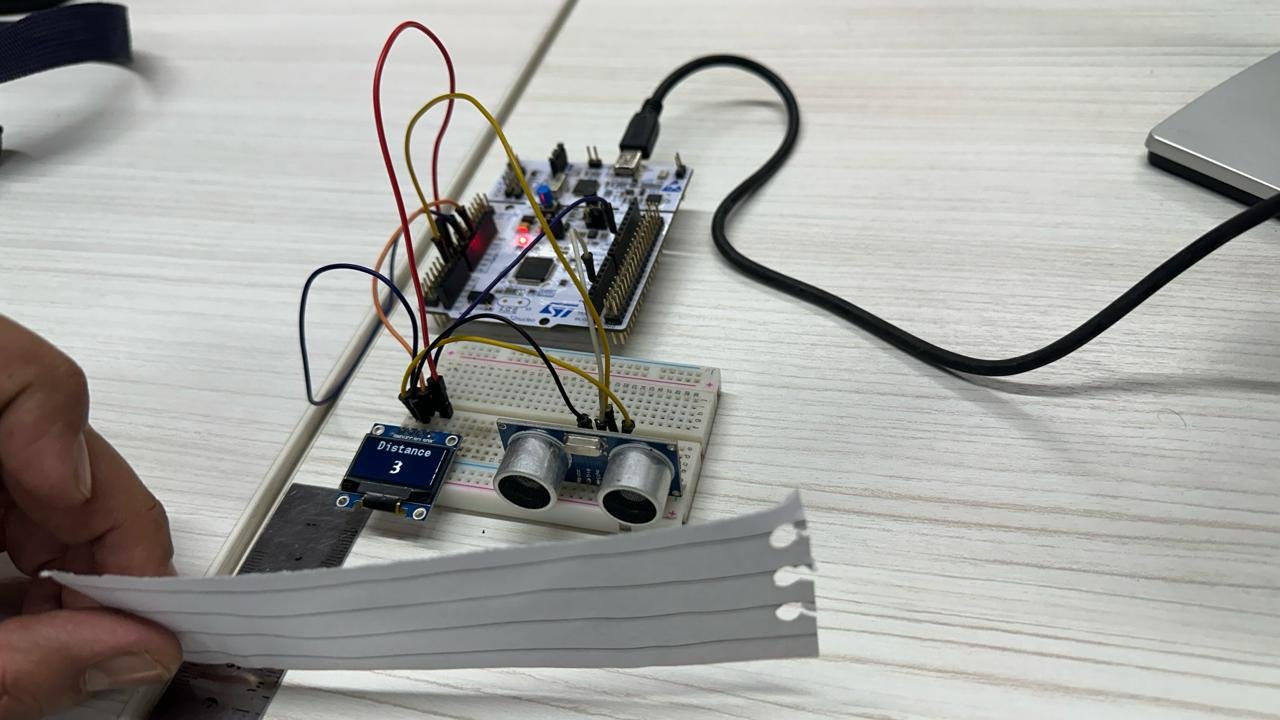
Once the code is uploaded to the board, the OLED will display the distance values in centimeters. Align an object parallel to the ultrasonic sensor and move it around to see the distance measurements change on the OLED.
Watch the video below:
Conclusion
In conclusion, this tutorial has provided a comprehensive overview of using the HC-SR04 ultrasonic sensor with the STM32 Nucleo board, showcasing how to program it with STM32CubeIDE and HAL libraries for accurate, contactless distance measurement. By connecting the SSD1306 OLED display, we demonstrated how to visualize these distance readings in real-time, enhancing the functionality of your project. With the guidance provided, you should now have a solid understanding of interfacing these components, enabling you to expand your skills and explore more advanced applications in embedded systems.
Required components:
| Quantity | Component | Amazon.com |
|---|---|---|
| 1 | STM32 Nucleo Development Board with STM32F446RE MCU NUCLEO-F446RE | Buy here |
| 1 | Breadboard Jumper Wires Kit | Buy Here |
| 1 | HC-SR04 ultrasonic sensor | Buy here |
| 1 | OLED | Buy here |
You may also like to read:
- SSD1306 OLED with STM32 Nucleo using STM32CubeIDE
- HC-05 Bluetooth Module with STM32 Nucleo using STM32CubeIDE
- STM32 Nucleo Timer in Counter Mode with STM32CubeIDE and HAL Libraries
- STM32 Nucleo Timer Encoder Mode with Rotary Encoder Example
- STM32 Nucleo Generate PWM with Timers using STM32CubeIDE
- STM32 Nucleo ADC with Polling, Interrupt and DMA STM32CubeIDE
- STM32 Nucleo Timer Input Capture Mode with Frequency Measurement Example
Related HC-SR04 Ultrasonic Sensor tutorials:
- Arduino Rosserial Publish Range HC-SR04 Ultrasonic Readings to ROS
- HC-SR04 Ultrasonic Sensor with STM32 Blue Pill using STM32CubeIDE
- HC-SR04 Ultrasonic Sensor with Raspberry Pi Pico using MicroPython
- IoT based Contactless Water level Monitoring with ESP32 and HC-SR04
- MicroPython HC-SR04 Ultrasonic Sensor with ESP32 and ESP8266
- HC-SR04 Ultrasonic Sensor Interfacing with Arduino – Distance Measurement Example