LM324 is a quad OP-AMP IC consisting of four high gain amplifiers. These four OP-AMPs can be operated from a single voltage source. However, the split voltage supply operation is possible too. The frequency compensation is provided internally to make OP-AMPs work over wide range frequencies. The supply current drain is almost independent of voltage supply in LM324. Its compatibility with all sorts of logic is commendable. Temperature compensation is possible for bias current at the input and cross-frequency at gain equal to unity. The need for two power supplies for its operation is eliminated. The differential input voltage is equal to ground voltage and a large DC voltage gain of 100 can be easily achieved as well.
Pinout Details LM324
LM324 comes in 14 pins as CDIP, PDIP, SOIC, and TSSOP. You can consult the datasheet for the physical dimension for all packages. The pinouts diagram and their details are shown as:
| PINS | Details |
|---|---|
| 1 (Out 1-Output 1) | This pin is for obtaining output of 1st OP-AMP |
| 2 ( Input 1-inverting Input) | This pin is for applying inverting input voltage to 1st OP-AMP |
| 3 ( Input 1- non-Inverting Input) | This pin is for applying non-inverting input voltage to 1st OP-AMP |
| 4 (Vcc) | This pin is for connecting supply voltage. |
| 5 ( Input 2- non-Inverting Input) | This pin is for applying non-inverting input voltage to 2nd OP-AMP |
| 6 ( Input 2-inverting Input) | This pin is for applying inverting input voltage to 2nd OP-AMP |
| 7 (Out 2- Output 2) | This pin is for obtaining output of 2nd OP-AMP |
| 8 (Out 3- Output 3) | This pin is for obtaining output of 3rd OP-AMP |
| 9 ( Input 3-inverting Input) | This pin is for applying inverting input voltage to 3rd OP-AMP |
| 10 ( Input 3- non-Inverting Input) | This pin is for applying non-inverting input voltage to 3rd OP-AMP |
| 11 (Vee, GND) | This pin is for connecting ground for single voltage operation or the second as Vee for dual power supply operation |
| 12 ( Input 4- non-Inverting Input) | This pin is for applying non-inverting input voltage to 4th OP-AMP |
| 13 ( Input 4-inverting Input) | This pin is for applying inverting input voltage to 4th OP-AMP |
| 14 (Out 4- Output 4) | This pin is for obtaining an output of 4th OP-AMP |
Equivalent options
Other equivalents of this op-amp are LT1014, LT1014A, LM124, LM128, LM224, LM248
Alternative options
Other Alternative options are AD620, LM4871, LM709, LM201
LM324 Quad OP-AMP Features
The operational electrical specification and features of LM324 are shown as:
| Parameters | LM324 |
|---|---|
| Input offset voltage (mV) | 3 |
| Input bias current (nA) | 100 |
| Input Offset Current (nA) | 30 |
| Input Common Mode Voltage Range (V) | -1.5 |
| Large signal voltage gain (V/mV) | 100 |
| Supply current (mA) | 3.0 |
| Common mode rejection ratio (dB) | 85 |
| Amplifier-to-Amplifier Coupling (dB) | -120 |
| Supply voltage Rejection Ratio (dB) | 100 |
| Supply Voltage (V) | 32 |
| Power dissipation-PDIP (mW) | 1130 |
| Power dissipation-CDIP (mW) | 1260 |
| Power dissipation-SOIC Package (mW) | 800 |
| Junction-to-ambient thermal Resistance (°C/W) | 88 |
| Differential Input voltage (V) | 32 |
| Output Short Circuit to Ground (Single Amplifier) | Continuous |
| Lead temperature (Soldering, 10s) (°C) | 260 |
| Junction temperature (°C) | 70 |
Where and How to Use?
LM324 can be operated by a single power source. Two power supplies can also be used. The terminals or the pins used are pin no. 4 and 11. This single supply or two power supplies will make all four OP-AMPs operative. For first OP-AMP, inverting input is applied at pin. No 2 and non-inverting at pin no. 3. The output of the first OP-AMP is obtained at pin no. 1. For second OP-AMP, inverting input is applied at pin. No 6 and non-inverting at pin no. 5. The output of second OP-AMP is obtained at pin no. 7. For third OP-AMP, inverting input is applied at pin. No 9 and non-inverting at pin no. 10. The output of third OP-AMP is obtained at pin no. 8. For fourth OP-AMP, inverting input is applied at pin. No 13 and non-inverting at pin no. 12. The output of fourth OP-AMP is obtained at pin no. 14.
LM324 Example Circuits
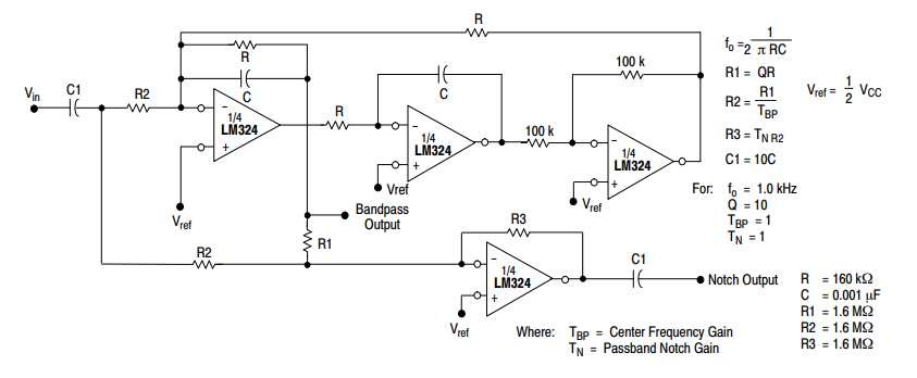
Bi-Quad Filter Example
One of the application making use of all four OP-AMPs of LM324 IC is Bi-Quad Filter which is shown as:
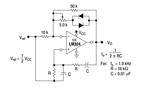
Wien-bridge oscillator Example
The use of LM324 for the use of Wien-bridge oscillator is shown in the circuit diagram below:
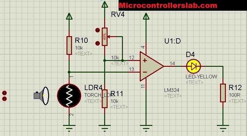
Dark Detector Example using LM324
In this dark detector example, LM324 is used as a comparator. The light-dependent resistor is type of a light sensor. LDR resistance changes based on light intensity available in its surroundings. Therefore, we can use this Photoresistor as a light sensor to detect darkness or measure light. We can also measure light with LDR.
You can read these photodetector based projects also:
- Light-dependent resistor interfacing with pic microcontroller
- light sensor and street light control using Arduino
- Auto intensity control of street lights using pic microcontroller
In the above mentioned projects, we interface LDR with a microcontroller. However, in this dark detector example, LM324 is used instead of a microcontroller.
Dark Detector Working
Working of this circuit is very simple.
- We connect an LED through a 100Ω at the output terminal of op-amp pin number 14.
- This is an indicator LED. It turns on as soon as LDR detects light.
- When there is a light around LDR, LED remains off.
- LM342N is used as a comparator. The inverting terminal connects with LDR output and Non-inverting connects with a variable resistor.
- When the voltage on pin 13 is greater than the voltage on pin 12, the comparator output gives 5-volt output.
- This output voltage provides forwarding voltage to LED and makes it glow.
LM324 Applications
The applications of LM324 are:
- Voltage reference provider
- Wein bridge oscillator
- Voltage follower
- Function generator
- Unity gain inverting amplifier
- High impedance differential amplifier
- Comparator with hysteresis
- Bi-quad filter
- Triangular wave generator
- Multiple feedback bandpass filter
- Instrumentation amplifier
- Square wave generator
- Comparator with hysteresis
2D physical diagram
The mechanical dimensions of PDIP 14-pin are shown as:


