RC522 is a Multi-communication RFID Module for Arduino and Microcontrollers. The RC522 is known as MFRC-522 due to its NFX semiconductor microcontroller. The module allows the developers to interface it with any other SPI, I2C, and UART based microcontrollers. The RC522 module works on 13.56 MHz frequency and it can act as a reader and write for UID/RFID cards. The RFID cards communicate with the module at a short distance with radio frequency due to the mutual induction technique. In most of the security and commercial products, the module is effective because the errors and issues with RFID Tags are detectable by it.
RC522 Pin Configuration Details
In this module, there are only two kinds of pins. So, the first one is power and the second one is the communication pins. Therefore, the device may have its microcontroller chip on itself but it only makes it to works as an RFID. The onboard microcontroller won’t make the module a stand-alone device.
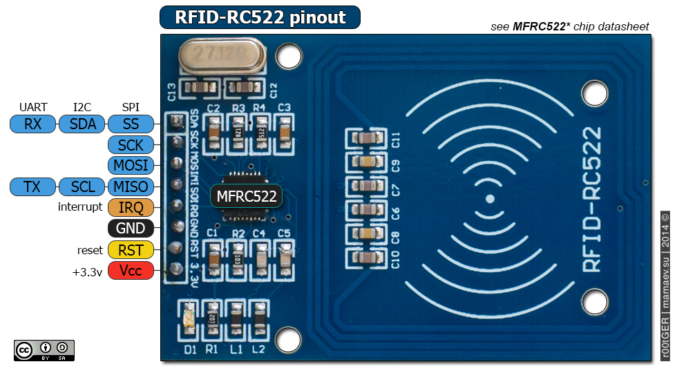
RC522 Pinout Diagram
All the pins of MFRC/RC522 RFID card Reader are:
Power/Reset Pins
| PINS | DETAILS | |
|---|---|---|
| Pin 1 | VCC | The power pins are VCC. In some versions of RC522, this pin is denoted by 3V3 on the module instead of VCC. |
| Pin 2 | RST | It’s a reset pin for the module. Therefore, it uses to reset the device in case of an error on when a device isn’t giving any response. |
| Pin 3 | Ground | Ground helps to make the common ground with every external device, e.g. power Supply, Microcontroller or Arduino. |
SPI and UART Communication Pins
| PINS | DETAILS | ||
|---|---|---|---|
| Pin 4 | IRQ | The device can go into sleep mode to save power. So, the IRQ helps to wake it. | |
| Pin 5 | MISO | SCL TX | This pin connects with the Arduino/Microcontrollers for SPI communication. However, it transfers the data from module to Arduino. The MISO pin is also useable for other functions instead of SPI. It can also interface with I2C for clock pulse and UART Serial for Data transfer from the module. |
| Pin 6 | MOSI | MOSI is the data input pin for RFID module in SPI communication | |
| Pin 7 | SCK | The SCK pins help to send the clock pulse in SPI communications. | |
| Pin 8 | SS | SDA RX | The SS pin is a chip enable pin in SPI communication. Therefore, it receives the signal when Master (Arduino) must perform SPI communication. The SS pin in RFID is useable as a second pin (SDA) for I2C communication. It also receives data during UART communication. |
RC522 RFID Reader Features
- RFID RC522 uses mutual induction to activate the cards and 13.56MHz for data transfer.
- The RFID Cards are useable from both sides of the module at max 5cm.
- The only 3.3V is required to activate the device.
- Its auto-sleep mode makes it less power consumption module.
- The module has three kinds of communications (UART, SPI, I2C). Therefore, it is useable with almost every microcontroller or device in the market.
- The RFID cards and reader (RC522) can transfer data up to 10Mb/s.
Alternative Option
RC522 RFID Module Applications
- RFID has most of the usage as a security device.
- In some companies, the devices use with shopping items.
- Some airports also start using RFID to identify and keep track of bags and other items.
- The attendance or Parking system also uses RFID to keep the system secure.
How to Use RC522 RFID Reader
The RC 522 usage is simple and complex at the same time. Even its library has too much complexity to understand. First, understand that library examples and documentation are all for SPI but the same library is useable for other UART and I2C Serial communication.
Arduino Interfacing Example
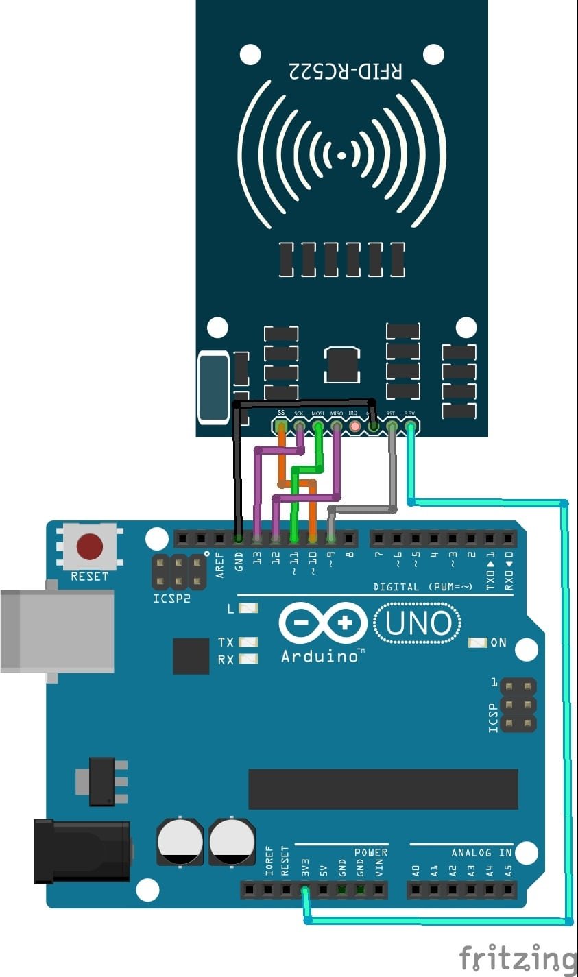
To use the RC522 with Arduino, which is the most popular board with this module, the following circuit needs to follow. So, here’s the circuit diagram:
Almost every board has specific pins for SPI communication. In SPI pins only SS pin is changeable others need to be according to the device. Therefore, in the above circuit diagram, the RFID connects with Arduino UNO through its specific SPI pins.
Programming RC522 RFID Reader
After designing the circuit, the following two libraries are required:
#include <SPI.h>
#include <MFRC522.h>
The MFRC522 library helps to decode and encode the incoming data from the RFID module and SPI helps to establish the SPI communication. These two libraries are dependent on each other. After initializing the libraries, the most important thing is to describe the reset and slave select (SS) pin through the following command:
MFRC522 mfrc522(SS_PIN, RST_PIN);
In the above command change the SS_PIN with Slave select and RST_PIN with reset pin of the RFID. So, after the above commands, the initialization of the circuit will complete. Now the developers must describe the SPI initialization and Module initialization which needs to be done by the following two objects.
SPI.begin();
mfrc522.PCD_Init();
Till these two objects, the communication and initialization of modules will complete but the above part is a little complex for some developers. The RC522 library offers multiple commands but to use those commands/objects every developer must understand some features.
Card Detect Code part
In the RC522 the RFID cards are readable but whenever a new card is present near the module, it is readable unless it isn’t present in the RC522. Here’s the question arise How a card can store in the module? Whenever a card is read by the module it stores itself unless a default data which is “FFFFFFFFFFFFh”. The following command will make the default key to the module.
MFRC522::MIFARE_Key key;
for (byte i = 0; i < 6; i++) key.keyByte[i] = 0xFF;
MIFARE_Key will automatically able to access the module keys and the loop will help to store the default ones.
Reading Card Value
The detection of the card is simple and easy whenever the default value is according to its factory setting. Once the values are set to default the following commands will able to detect the new card
mfrc522.PICC_IsNewCardPresent()
mfrc522.PICC_ReadCardSerial()
The first command is for card detection and the next command is to read the data. Sometimes the card can be present on the module but it has no data. Therefore, the second command ReadCardSerial will help to detect that. After that use to the following command to see the dumb the data so it can decrypt:
mfrc522.PICC_DumpDetailsToSerial(&(mfrc522.uid));
mfrc522.PICC_DumpToSerial(&(mfrc522.uid));
Use the first one for decimal and the second one for HEX. It helps store and read the data code. Always remember the device can read and dump/decrypt the data of a single card at a time. Therefore, During Dumping the device won’t be able to read the new card.
Reading Status of RFID Card
In RC522 the RFID cards status is readable. If somehow the authentication of the card gets failed or unreadable then the program can tell the microcontroller so it doesn’t get stuck. Therefore, the status may not look reliable but in some cases, it gives the developers to run specific instructions to remove the error. So, the following command will help to initialize the status:
MFRC522::StatusCode status //To read the status
mfrc522.PCD_Authenticate //To get the authentication
mfrc522.MIFARE_Read //To read the card
The above commands are just the main symbols but the rest of the commands will depend on the data.
Stop RFID Card Reading
In RC522 once the card read commands has sent to the card, it will never stop until a stop command is sent. Even to stop the encryption the commands need to send from the microcontroller. Therefore, the stops commands for both functions will be:
mfrc522.PICC_HaltA(); // Stop reading
mfrc522.PCD_StopCrypto1(); // Stop encryption on PCD
The above commands are just simple reading commands with RC522 but now there are a bunch of other operations that can be done by RC522. Therefore, the following manual can help:
Tutorials and Projects
Other tutorials and projects that use RFID Card reader modules:
- Door Security System Using RFID RC522 and Arduino
- RFID Based Attendance System project using pic microcontroller


