In this tutorial, we will learn to use GPIO pins of STM32 Nucleo and we will demonstrate it with an LED blinking example using STM32CubeIDE and HAL libraries. We will see how to configure the GPIO pins of STM32 Nucleo as digital output pins.
If you’re a beginner in STM32 Microcontrollers, this article will be a perfect starting point. We will guide you through the process of setting up your STM32 Nucleo board using STM32CubeIDE. With the help of HAL (Hardware Abstraction Layer) libraries provided by STMicroelectronics, we will explore how to utilize GPIO (General Purpose Input/Output) pins to control and manipulate LEDs. Let’s get started with your path to learning STM32 Nucleo programming.
Whenever any beginner starts learning any microcontroller development board, Experts always recommend beginners start with an LED blinking example. LED blinking examples to use general-purpose input-output pins to turn on and turn off the LED.
As discussed earlier, we will be using STM32CubeIDE, therefore, you should have the latest version installed on your system. You can follow this guide to install it:
STM32 Nucleo Boards Introduction
ST Microelectronics introduced powerful, low-cost, and affordable development boards as compared to STM32 discovery boards. Because discovery boards have higher prices than Nucleo boards. These boards allow you to develop and prototype your application quickly at a low cost. Most importantly, they are compatible with a large number of hardware add-ons available for Arduino Uno and Arduino Nano.
Three are three main types of Nucleo boars which are classified in terms of flash size, high performance, ultra-low power, and wireless capability features such as Nucleo-32, Nucleo-64, and Nucleo-144.
There are different programming environments are available to program Nucleo boards such as Arduino, STM32CubeMX, Mbed, Zephyr RTOS, etc. But we will use STM32CubeIDE and HAL libraries framework in this series of tutorials.
STM32 Nucleo GPIO Pins
As discussed in the last section, there are many variants of STM32 Nucleo boards available. You can use any one of these boards. But the one which we are going to use in this tutorial is a Nucleo-F103RB board. But you can use any other Nucleo board also and follow the same instructions to use GPIO pins as digital output pins.
The Nucleo-F103RB board comes with an STM32F103RBT6 microcontroller which is ARM®32-bit Cortex®-M3 CPU. Various features of Nucleo-F103RB are mentioned below:
| Features and Peripherals | Numbers and Range |
|---|---|
| Operating voltage range | VDD from 2.0 V to 3.6 V |
| Flash Size | 128KB |
| SRAM Size | 20KB |
| GPIO Pins | 51 |
| ADC | 12-bit ADC (2) with 16 channels |
| RTC | 1 |
| Timers | 4 |
| I2C | 2 |
| USART | 3 |
| SPI | 2 |
| CAN | 1 |
According to the above table, this STM32 Nucleo board has 51 general-purpose input-output pins. We can use any one of these pins as a digital input or digital output.
Each GPIO pin may have multiple functions. But you can use only one functionality at a time. The following diagrams of different connectors of the Nucleo-F103RB board show various GPIO pins for UART, I2C, SPI, ADC, CAN, Timers output, and USB communication.


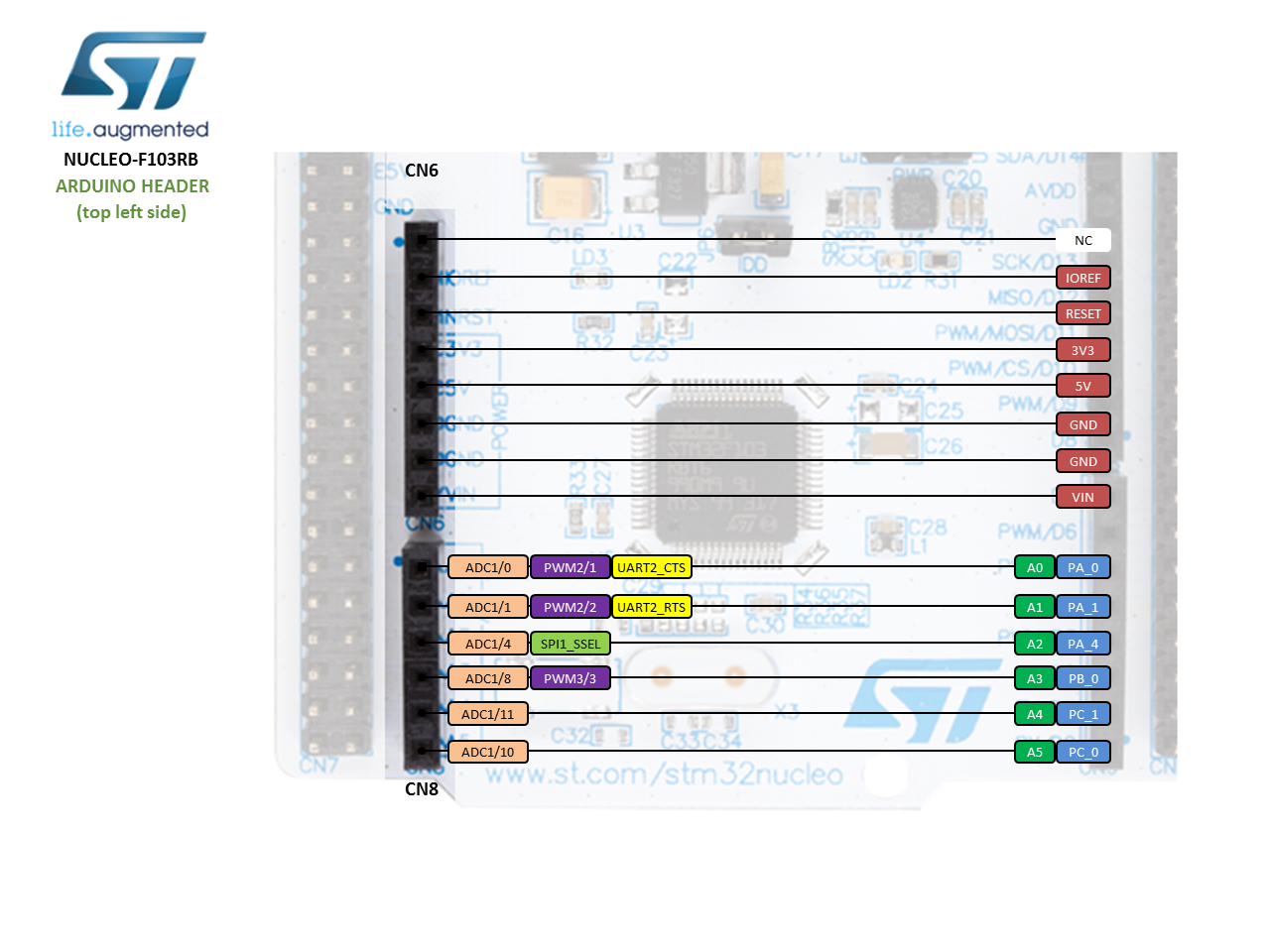
For more information on GPIO pins and to check the pinout of Nucleo-F103RB, you can refer to this link.
STM32 Nucleo LED Blinking Example
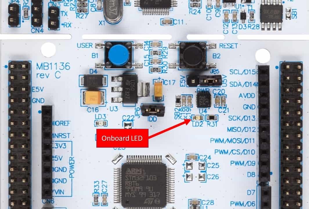
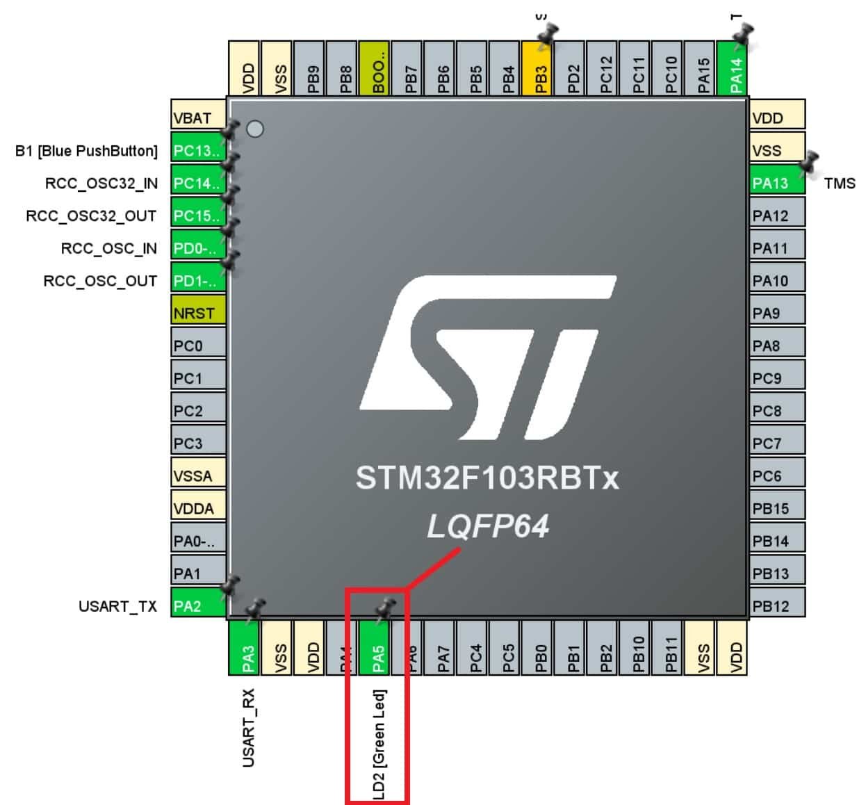
As mentioned earlier, we will learn to use GPIO pins of STM32 Nucleo as digital output pins. For demonstration purposes, In this example, we will control an onboard LED of STM32 Nucleo-F103RB board. This STM32 Nucleo board has an onboard LED with the name of LD2 and it is connected with the PA_5 pin of F103RB as shown below:
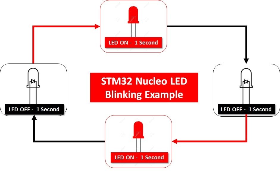
This LED blinking example works as mentioned below:
- Onboard LED Turns on for one second which means GPIO PA_5 goes to active high state
- In next step, LED turns off for one second which means GPIO PA_5 goes to active low state
- Above two steps keep repeating as shown below:
First, let’s see how to write the first program for STM32 Nucleo in STM32CubeIDE.
Write your first STM32 Nucleo in STM32Cube IDE
After installing STM32CubeIDE on your Windows, Linux, or MacOS system, follow these steps to create an LED blinking project. In this section, you will learn the followings:
- create and configure the STM32CubeMX project and generate the initialization code
- program and use HAL functions to blink a LED on the NUCLEO-F103RB board.
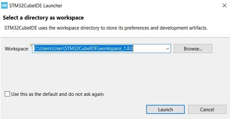
Launch STM32CubeIDE: Open the STM32CubeIDE application on your computer. You will be asked to specify the directory for the workplace. You can specify the directory and also tick the box below to keep this as the default directory. Next, click ‘Launch’ to start the application.
Creating STM32 Nulceo Project
The STM32Cube workspace will open.
Now click ‘Start new STM32 project’.

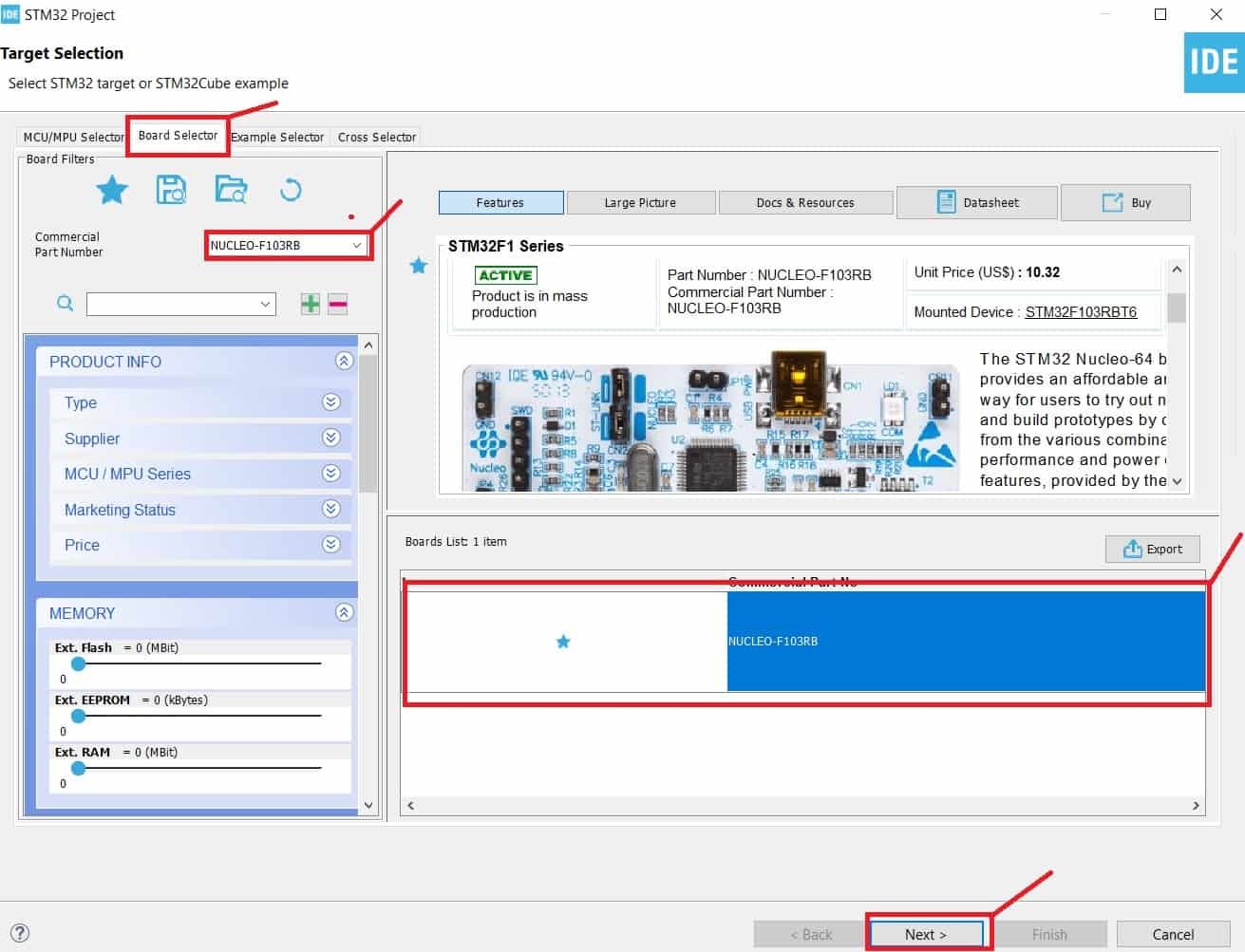
From Board Selector section, type STM32 Nucleo-F103RB and select it. Click next.
Give your project a name. As we are going to blink the on-board LED of STM32 Nucleo-F103RB hence we have named our project ‘BLINK_LED.’ Then click ‘Finish.’

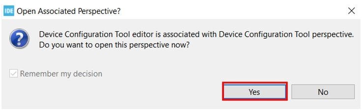
You will be asked to open an associated perspective to start generating code with STM32CubeMX. Click ‘Yes’.
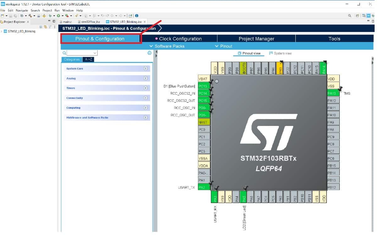
Device Configuration Tool
Now the Device Configuration Tool window will open up. In the pinout and configuration window, we can select a specific pin and its function. A single GPIO pin may have multiple alternate functions. For example, the same GPIO pin can be used for ADC, SPI, UART peripherals, etc. But only one function can be used at a time.
Select GPIO Pin
As mentioned earlier, we will see an LED blinking example in this tutorial, and for demonstration purposes, we will use an onboard LED of STM32 Nucleo-F103RB board. The onboard LED of Nucleo-F103RB board is connected with a PA5 pin. When you create a project for Nucleo-F103RB, you will see that it has already been configured for the PA5 pin. But you can change it according to your requirement.
Click on the PA5 pin, and a list of all alternate functions will appear associated with the PA5 pin. We will set this pin as a ‘GPIO Output.’
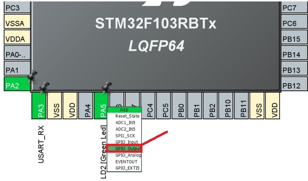
This is how it will look. Here you can see that we have attached GPIO_Output to PA5.
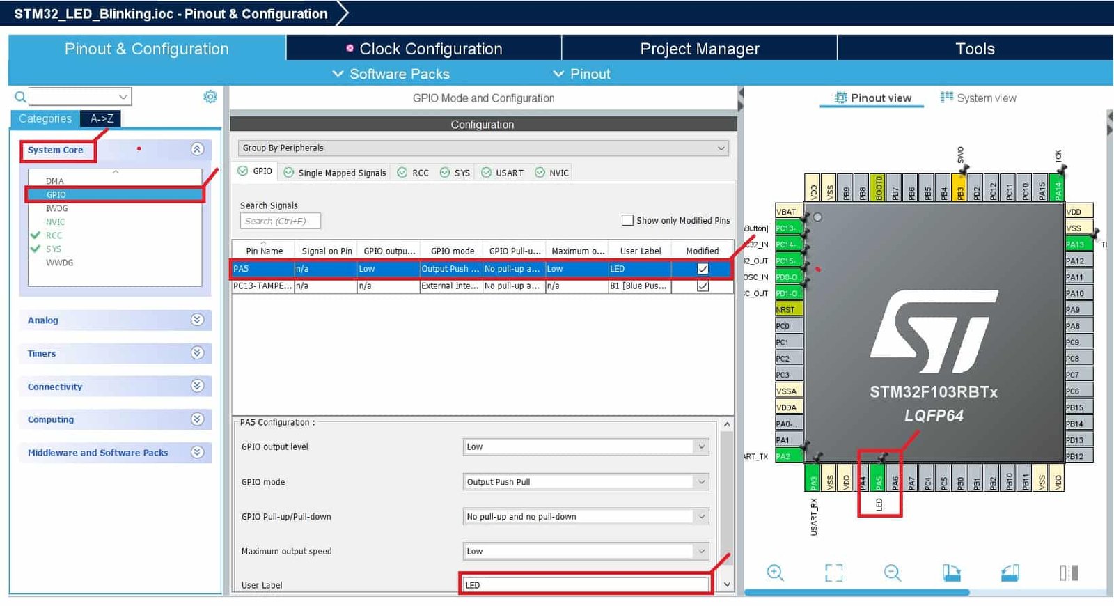
Additionally, we have more options for pins as well. Go to System Core > GPIO > PA5 and the pin configuration for PA5 will open up. Here we have given the pin a user label of ‘LED.’ You can see in Device Configuration Tool, that now PA5 has been given the label ‘LED.’
Apart from the label, there are several other options to choose from including GPIO output level, mode, pull-up/pull-down state, etc.
In the GPIO Tab, select Pin Name column PA5 to display the corresponding GPIO parameters and configuration to drive the Nucleo-F103RB LED:
- GPIO Output level: By default, the output level is set to Low, meaning the pin is at a low voltage. However, you can change it to High if needed.
- GPIO mode: The mode automatically configures the pins with the appropriate alternate function and sets them to Output Push Pull mode, ensuring compatibility and stability.
- GPIO Pull-up/Pull-down: By default, no pull-up or pull-down resistors are enabled. However, depending on your requirements, you can configure pull-up or pull-down options if supported by the specific pin.
- GPIO Maximum output speed: The maximum output speed is initially set to Low for power consumption optimization. However, if your application requires a higher frequency, you can change this setting accordingly.
- User Label: This is a customizable name assigned to a GPIO pin for easier identification and access. You can assign a meaningful label, and later use the Find menu to locate and work with the GPIO pin based on its label.
These configurations and parameters allow you to customize the behavior of the GPIO pins to suit the needs of your specific project and ensure proper functionality.
Now we will save our file. Press Ctrl + S. The following window will appear. Click ‘Yes.’ This will generate a template code for you.

Another window will appear that will ask if you want to open the perspective. Click ‘Yes.’
STM32CubeMX Generated Code
Now the following page opens. On the right side, you will be able to view the Outline of the code. In the center, you can view the main.c file and on the left, you can view the Project Explorer. If you want to go to the Device Configuration Tool, then click the BLINK_LED.ioc tab.
STM32CubeMX will add all required HAL libraries and system level HAL libraries to use the PA5 pin of STM32 Nucleo as a digital output pin.

STM32 Nucleo LED Blinking Code
Now let’s modify the main.c file for our BLINK_LED project. Our aim is to blink the onboard LED indefinitely after a delay.
First, inside the main() function go to while(1) and insert the following lines of code. These will be responsible to blink the onboard LED infinitely.
 while (1)
  {
    /* USER CODE END WHILE */
	  HAL_GPIO_TogglePin(GPIOA, GPIO_PIN_5); // Toggle the GPIO pin state
	  HAL_Delay(1000); // Delay for 1000 milliseconds
    /* USER CODE BEGIN 3 */
  }
Save the main.c file after modifying it. Now we are ready to build our project.
SMT32 GPIO HAL Driver
In this section, we will see an overview of HAL GPIO libraries. This is just for your information and in your code you only need to use these functions and need to understand how these functions work.
The HAL driver provides functions to control the GPIO pins of the STM32 family of microcontrollers. The GPIO pins can be configured in one of the following modes:
- Digital Input mode
- Analog modeD
- Digital Output mode
- Alternate function mode
- External interrupt/event lines
“stm32f1xx_hal.h” header file contains function prototypes of all the peripherals of STM32F1 microcontrollers.
GPIO_InitTypeDef C structure is used to initialize and set the mode of GPIO pins.
typedef struct
{
  uint32_t Pin;       /*!< Specifies the GPIO pins to be configured.
                           This parameter can be any value of @ref GPIO_pins_define */

  uint32_t Mode;      /*!< Specifies the operating mode for the selected pins.
                           This parameter can be a value of @ref GPIO_mode_define */

  uint32_t Pull;      /*!< Specifies the Pull-up or Pull-Down activation for the selected pins.
                           This parameter can be a value of @ref GPIO_pull_define */

  uint32_t Speed;     /*!< Specifies the speed for the selected pins.
                           This parameter can be a value of @ref GPIO_speed_define */

  uint32_t Alternate;  /*!< Peripheral to be connected to the selected pins.
                            This parameter can be a value of @ref GPIO_Alternate_function_selection */
}GPIO_InitTypeDef;
Another important C struct is a GPIO_TypeDef. The members of the GPIO_TypeDef C struct are the configuration and control registers of GPIO ports.
typedef struct
{
  __IO uint32_t MODER;    /*!< GPIO port mode register,               Address offset: 0x00      */
  __IO uint32_t OTYPER;   /*!< GPIO port output type register,        Address offset: 0x04      */
  __IO uint32_t OSPEEDR;  /*!< GPIO port output speed register,       Address offset: 0x08      */
  __IO uint32_t PUPDR;    /*!< GPIO port pull-up/pull-down register,  Address offset: 0x0C      */
  __IO uint32_t IDR;      /*!< GPIO port input data register,         Address offset: 0x10      */
  __IO uint32_t ODR;      /*!< GPIO port output data register,        Address offset: 0x14      */
  __IO uint32_t BSRR;     /*!< GPIO port bit set/reset register,      Address offset: 0x18      */
  __IO uint32_t LCKR;     /*!< GPIO port configuration lock register, Address offset: 0x1C      */
  __IO uint32_t AFR[2];   /*!< GPIO alternate function registers,     Address offset: 0x20-0x24 */
} GPIO_TypeDef;
Configure GPIO pins as Digital Output
HAL GPIO library provides these functions to control, initialize and de-initialize GPIO pins.
HAL_GPIO_Init() function initializes the GPIOx according to the input arguments specified to both parameters. Here the GPIOx can be (x=A, B, C…H, I) according to which GPIO port we want to use. GPIO_Init is a pointer to the struct GPIO_InitTypeDef which configuration information for the specified GPIO peripheral.
void HAL_GPIO_Init(GPIO_TypeDef *GPIOx, GPIO_InitTypeDef *GPIO_Init)For example, if we use GPIO PORTB of STM32 as digital output pins such as PB12, PB13, PB14, and PB15. To initialize them as a digital output, first, we create a struct variable of any name “BoardLEDs” of type GPIO_InitTypeDef.
GPIO_InitTypeDef BoardLEDs;By using members of the GPIO_InitTypeDef struct, we select the mode of boardLEDs as a digital output and also select GPIOD pins by using BoardLEDs.Pin member of the GPIO_InitTypeDef.
BoardLEDs.Mode = GPIO_MODE_OUTPUT_PP;
BoardLEDs.Pin = GPIO_PIN_12|GPIO_PIN_13|GPIO_PIN_14|GPIO_PIN_15;
After that, we pass the reference of the “BoardLEDs” struct to HAL_GPIO_Init() function along with GPIO port name which is GPIOD to initialize PD12-PD15 pins of PORTD as digital output pins.
GPIO HAL Driver Toggle LED Function
HAL GPIO driver provides toggle function HAL_GPIO_TogglePin() which can be used to toggle any GPIO pin STM32 Microcontrollers. For example, we want to toggle onboard LED of STM32 nucleo.
To use this function, specified the GPIO port and its pin number to which you want to toggle.
void HAL_GPIO_TogglePin(GPIO_TypeDef* GPIOx, uint16_t GPIO_Pin)HAL GPIO Write Pin Function
This function is used to set or clear a specified pin of a GPIO port. The first input argument is a PORT name, the second input argument is a pin number of the selected PORT and the third input argument is the state of the pin which can be GPIO_PIN_RESET or GPIO_PIN_SET.
- GPIO_PIN_RESET -> clear the port pin to active low
- GPIO_PIN_SET -> set the port pin to active high
void HAL_GPIO_WritePin(GPIO_TypeDef* GPIOx, uint16_t GPIO_Pin, GPIO_PinState PinState)To blink the onboard LED of STM32 Nucleo board with HAL_GPIO_WritePin() function, we can set the corresponding pins for one second and then reset the pins for one second.
HAL_GPIO_WritePin(GPIOA, GPIO_PIN_5, GPIO_PIN_SET);
Delay_ms(1000);
HAL_GPIO_WritePin(GPIOA, GPIO_PIN_5, GPIO_PIN_RESET);
Delay_ms(1000);
Building the Project
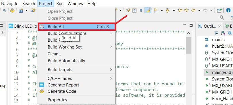
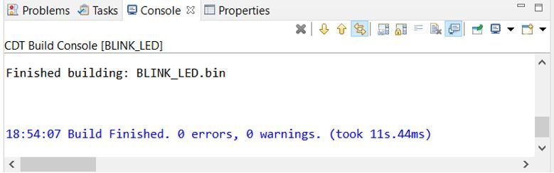
To build LED Blinking project press Ctrl + B or go to Project > Build All.
Your project will start building. After a few moments, your project will be built if there are no errors.
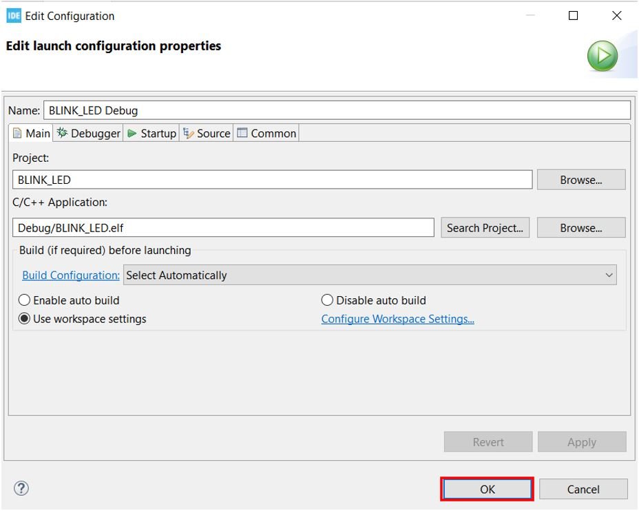
Connect STM32 Nucleo with your computer and next press the RUN button in the IDE. The following ‘Edit configuration’ window will open up. Click ‘OK’.
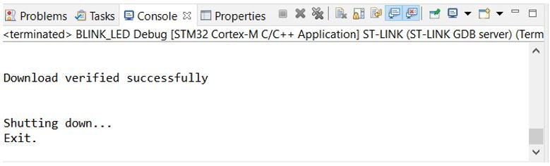
After a few moments, the code will be successfully sent to the STM32 board. You can view it in the Console terminal.
Otherwise, press the RESET button on your STM32 board.
After pressing the RESET button on the board. Immediately, the onboard LED will start blinking.

Conclusion
In conclusion, this tutorial provides a beginner-friendly approach to working with STM32 Nucleo boards using STM32CubeIDE and HAL libraries. By walking through the LED blinking example, you have learned how to configure and use the GPIO pins as digital outputs to control an LED. This foundational project is an excellent way to familiarize yourself with the STM32 environment and the use of HAL libraries for more complex applications. Whether you’re new to microcontroller programming or transitioning to STM32, this guide serves as a valuable first step in mastering the platform.
Required Components:
| Quantity | Component | Amazon.com |
|---|---|---|
| 1 | STM32 Nucleo Development Board with STM32F446RE MCU NUCLEO-F446RE | Buy here |
| 1 | Breadboard Jumper Wires Kit | Buy Here |
| 1 | LEDs and resistors kit | Buy Here |
Other STM32 Nucleo tutorials:
- Push Button with STM32 Nucleo using STM32CubeIDE
- GPIO External Interrupts STM32 Nucleo with STM32CubeIDE
- STM32 Nucleo UART Communication Tutorial with CubeIDE and HAL Libraries
- STM32 Nucleo UART Interrupt with STM32CubeIDE and HAL Libraries
- STM32 Nucleo UART DMA with STM32CubeIDE and HAL Libraries
- STM32 Nucleo Timer Interrupt with STM32CubeIDE and HAL Libraries
You may also like to read: