This STM32F4 Discovery Board LED blinking tutorial teaches you how to use the GPIO pins of the STM32F4 Discovery Board to blink the four onboard LEDs using the HAL (Hardware Abstraction Layer) library in Keil uvision IDE for ARM. It is the perfect starting point for learning STM32F407 programming, because LED blinking is the embedded “Hello World” — once you can toggle a GPIO pin with the HAL driver, the same pattern applies to buttons, relays, buzzers, motors, and almost every other output peripheral on the board.
In this guide we will use the onboard user LEDs of the latest STM32F4DISCOVERY board (MB997D / MB9970), but the same code, pin mappings, and concepts apply to every earlier revision of the board. By the end of this tutorial you will have set up a complete Keil uvision project for the STM32F407VGT6, installed the HAL drivers, written your first C program, and seen the LEDs blink on real hardware.
Recommended Components
The following components are used in this project or are helpful for getting started with STM32F4 Discovery board development.
| Component | How it’s used in this project | Buy on Amazon |
|---|---|---|
| STM32F4 Discovery Board (STM32F407G-DISC1) | The STM32F407VG Discovery development board used in this guide. | Check Price |
| Mini-USB Cable (Type-A to Mini-B) | Type-A to Mini-B cable to program and power the board over its onboard ST-Link. | Check Price |
As an Amazon Associate we earn from qualifying purchases. Prices and availability are accurate as of the date/time indicated and are subject to change.
What You Will Learn
- How GPIO pins of the STM32F407VGT6 are organized into ports and which ports are broken out on the Discovery header pins
- Which onboard LEDs (LD3, LD4, LD5, LD6) are connected to which PORTD pins and in what color
- How to install STM32F4 HAL drivers and board support packages inside Keil uvision
- How to create a new Keil project targeting the STM32F407VG microcontroller
- How to write STM32F4 LED blinking code using
HAL_GPIO_TogglePin()andHAL_GPIO_WritePin() - How the
GPIO_InitTypeDefandGPIO_TypeDefstructures work under the hood - How to troubleshoot the most common LED blinking issues on the STM32F4 Discovery Board
Prerequisites and Required Components
Before you start this STM32F4 LED blinking project, make sure you have the following hardware and software ready:
- STM32F4 Discovery Board (STM32F407G-DISC1, MB997D or MB9970)
- Mini USB cable to connect the board to your computer (the board uses the onboard ST-LINK/V2 for both programming and power)
- Keil uvision IDE (MDK-ARM) — the free community edition supports STM32F4 with a code size limit that is more than enough for this tutorial
- STM32F4 HAL device family pack (installed through Keil’s Pack Installer)
- Basic familiarity with C programming
Because the onboard LEDs are already wired to fixed pins on the Discovery Board, you do not need a breadboard, external LEDs, or current limiting resistors for this tutorial. That is one of the biggest advantages of using the Discovery kit to learn STM32 programming.
We use the HAL libraries throughout this series for a simple reason: HAL is officially developed and maintained by STMicroelectronics. Code written for the STM32F4 HAL can be ported to the F0, F1, F2, F3, F7, L0, L4, G0, and G4 families with minimal changes, which makes this LED blinking tutorial a transferable skill, not just a Discovery Board exercise.
STM32F4 Discovery Board GPIO Pins
The STM32F4 Discovery board features a 32-bit STM32F407VGT6 microcontroller, which belongs to the F4 family of ST microcontrollers and is based on ARM Cortex-M4 architecture with DSP and FPU. Microcontrollers in the STM32F407xx family support up to 140 GPIO pins with interrupt capability — of which up to 136 can operate as fast GPIOs up to 84 MHz, and up to 138 are 5 V-tolerant. The STM32F407VGT6 specifically exposes 82 GPIO pins, arranged into ports PORTA, PORTB, PORTC, PORTD, PORTE, PORTF, PORTG, PORTH, and PORTI. Each port contains up to 16 pins (pin 0 through pin 15).
Note: Not all ports have the full 16 GPIO pins broken out, because some pins are reserved for other functions such as oscillator inputs, JTAG/SWD, and power supply pins.
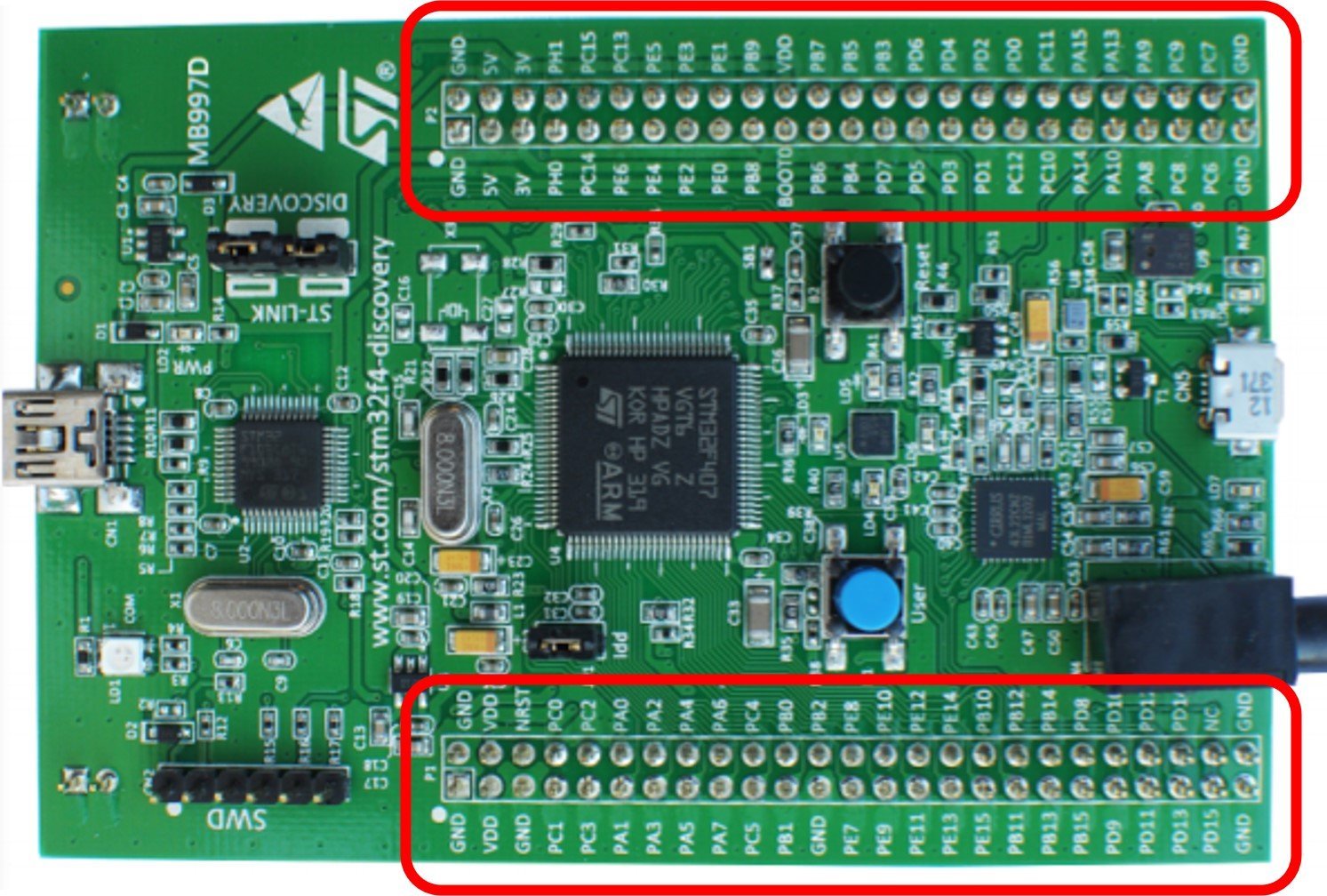
On the STM32F4 Discovery Board itself, five GPIO ports (PORTA, PORTB, PORTC, PORTD, PORTE) are brought out to the two 50-pin male headers on the sides of the board, giving you a total of 80 GPIO pins to work with for external connections, as shown in the figure below:
Onboard LEDs on the STM32F4 Discovery Board
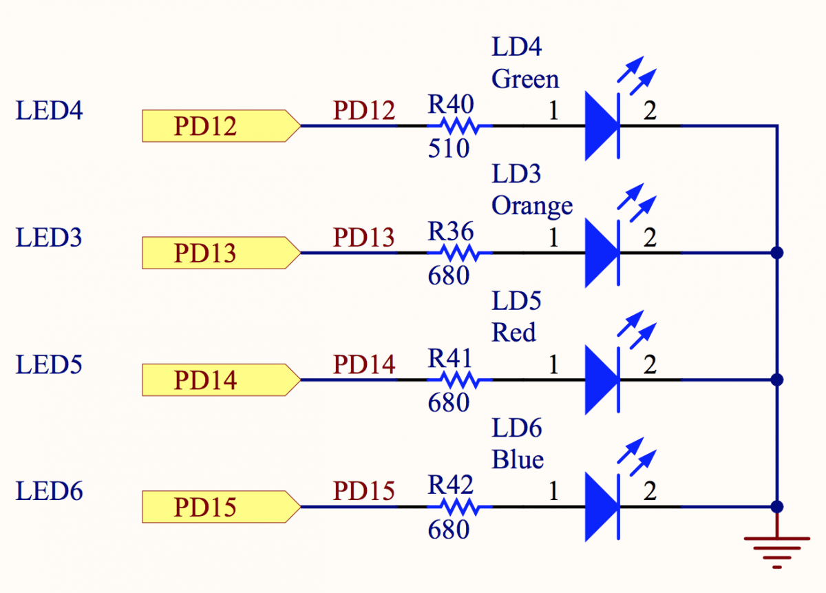
The Discovery board comes with four user LEDs connected to PD12, PD13, PD14, and PD15 of PORTD, each through a current-limiting resistor. This is why the LED blinking example focuses on PORTD pins 12 through 15 — the wiring is already done for you on the PCB.
| LED Color | LED Name | Pin Number |
|---|---|---|
| Green | LD4 | PD12 |
| Orange | LD3 | PD13 |
| Red | LD5 | PD14 |
| Blue | LD6 | PD15 |
- LD3: orange LED — connected to GPIO pin PD13 of the STM32F407VGT6
- LD4: green LED — connected to GPIO pin PD12 of the STM32F407VGT6
- LD5: red LED — connected to GPIO pin PD14 of the STM32F407VGT6
- LD6: blue LED — connected to GPIO pin PD15 of the STM32F407VGT6

Because all four LEDs sit on the same port (PORTD), we can enable the clock for a single GPIO port and control all four LEDs with one initialization block — a small efficiency that becomes important when you start writing more complex firmware.
In this LED blinking tutorial, we will see how to blink all four of these onboard LEDs using the HAL GPIO drivers in Keil uvision IDE.
Writing Your First Program for STM32F4 Discovery Board in Keil uvision
In this section you will create your first Keil uvision project for the STM32F4 Discovery Board from scratch, install the required HAL packages, and configure the run-time environment so the project compiles against the STM32F407VG device.
Step 1: Install STM32F4 HAL Drivers and Board Support Packages in Keil
First, download and install Keil uvision IDE (MDK-ARM) on your system. If you have not done this yet, follow our dedicated install guide:
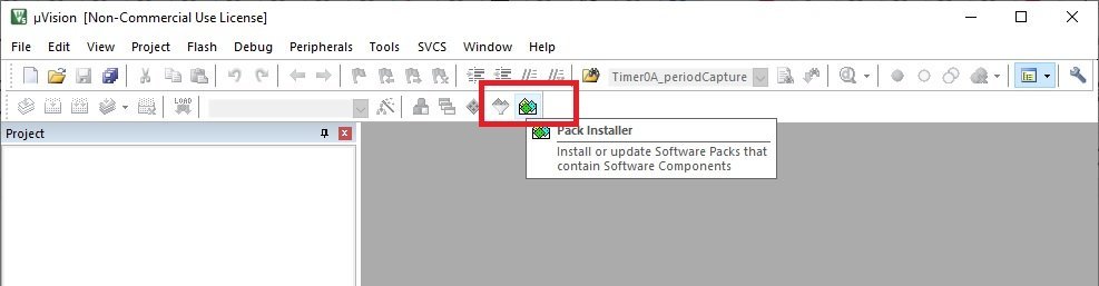
Once Keil is installed, open it and launch the Pack Installer to install the STM32F4 software packages and HAL libraries. Click the Pack Installer icon in the Keil toolbar:
The Pack Installer window will appear. In the left pane, expand STMicroelectronics → STM32F4 Series. When you double-click the STM32F4 series, the required software packages are listed on the right-hand side.
From the right pane select Device Specific and install the drivers for STM32F4 (and the STM32F4 Nucleo pack if you ever plan to use a Nucleo board too) by clicking the Install buttons one by one. This downloads the HAL drivers and board support packages for the entire STM32F4 family of microcontrollers, including the STM32F407VGT6 used on the Discovery Board.

Once the installation finishes, close the Pack Installer. You are now ready to create your first STM32F4 Discovery project in Keil uvision.
Step 2: Create a New Project in Keil uvision
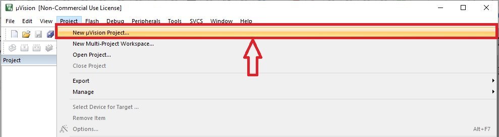
To create a new project for the STM32F4 Discovery Board, go to the Project menu and click New uvision Project.
Next, choose the location where you want to save your project. It is good practice to create a new folder dedicated to this project and give it a clear name (for example, STM32F4_LED_Blink):

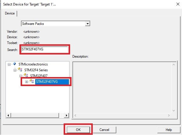
After saving, the “Select Target Device” window appears. In the search bar type STM32F407VG, select the microcontroller from the filtered options, and click OK.
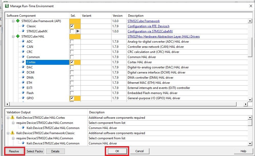
The Run-Time Environment window will appear next. This is where you pick which HAL modules your project needs. For STM32F4 LED blinking, make the following selections:
- CMSIS → tick CORE
- Device → tick Startup
- Device → STM32Cube Framework (API) → select Classic
- Device → STM32Cube HAL → tick the peripheral modules you need. For this tutorial we only need GPIO, RCC, PWR, Cortex, and Common. You can add more later (ADC, SPI, I2C, UART, etc.) as your projects grow.
Selecting these options may pull in additional software components. Any missing dependencies are shown at the bottom of the window. Click the Resolve button and Keil uvision will automatically enable the required dependencies for you.
Because this LED blinking tutorial uses the GPIO pins of the STM32F4 Discovery Board, make sure the GPIO HAL module is ticked under STM32Cube HAL before continuing.
After confirming your settings, click OK. The project is created and the Keil workspace should look like this:

Now add the main source file to the project. Right-click on Source Group 1, choose Add New Item to Group, select a C File (.c), and name it main. We will write the STM32F4 LED blinking code inside this file.
STM32F4 Discovery Board LED Blinking Program (HAL_GPIO_TogglePin)
The following LED blinking program toggles all four onboard LEDs (PD12, PD13, PD14, PD15) at a rate of 1 second. It uses the GPIO HAL module driver and the HAL_GPIO_TogglePin() function, which flips the current state of the specified pin on every call.
#include "stm32f4xx_hal.h"

void Init_OnBoard_LEDs(void);
void Delay_ms(volatile int time_ms);
int main(void)
{
	Init_OnBoard_LEDs();
	while(1)
	{
	HAL_GPIO_TogglePin(GPIOD,GPIO_PIN_12|GPIO_PIN_13|GPIO_PIN_14|GPIO_PIN_15);
	Delay_ms(1000);
	}
}

void Init_OnBoard_LEDs(void)
{
	 __HAL_RCC_GPIOD_CLK_ENABLE();
	GPIO_InitTypeDef BoardLEDs;
	BoardLEDs.Mode = GPIO_MODE_OUTPUT_PP;
	BoardLEDs.Pin = GPIO_PIN_12|GPIO_PIN_13|GPIO_PIN_14|GPIO_PIN_15;
	HAL_GPIO_Init(GPIOD, &BoardLEDs);
}
void Delay_ms(volatile int time_ms)
{
	      int j;
        for(j = 0; j < time_ms*4000; j++)
            {}  /* excute NOP for 1ms */
}
The Init_OnBoard_LEDs() function performs three essential steps: it enables the peripheral clock for PORTD using __HAL_RCC_GPIOD_CLK_ENABLE(), fills in a GPIO_InitTypeDef structure with the pin mode and pin mask, and passes that structure to HAL_GPIO_Init(). Without the clock-enable step, the GPIO registers will simply not respond — this is the single most common reason why STM32 LED blinking code compiles cleanly but does nothing on the board.
STM32F4 GPIO HAL Driver Explained
The HAL driver provides a clean, portable API to control the GPIO pins of the STM32F4 family of microcontrollers. Any GPIO pin can be configured in one of the following modes:
- Digital Input mode — read a logic level from the outside world (push buttons, logic signals)
- Analog mode — connect the pin to the ADC or DAC peripheral
- Digital Output mode — drive a logic high or low (LEDs, relays, transistors)
- Alternate Function mode — hand the pin over to a peripheral such as USART, SPI, I2C, TIM, or USB
- External Interrupt / Event lines — trigger an ISR on a rising, falling, or both-edge transition (EXTI)
The stm32f4xx_hal.h header file includes function prototypes and type definitions for all the HAL peripheral modules available on STM32F4 microcontrollers. Including this single header gives your code access to GPIO, ADC, SPI, I2C, UART, TIM, and every other HAL peripheral API.
The GPIO_InitTypeDef C structure is used to initialize and set the mode of GPIO pins:
typedef struct
{
  uint32_t Pin;       /*!< Specifies the GPIO pins to be configured.
                           This parameter can be any value of @ref GPIO_pins_define */

  uint32_t Mode;      /*!< Specifies the operating mode for the selected pins.
                           This parameter can be a value of @ref GPIO_mode_define */

  uint32_t Pull;      /*!< Specifies the Pull-up or Pull-Down activation for the selected pins.
                           This parameter can be a value of @ref GPIO_pull_define */

  uint32_t Speed;     /*!< Specifies the speed for the selected pins.
                           This parameter can be a value of @ref GPIO_speed_define */

  uint32_t Alternate;  /*!< Peripheral to be connected to the selected pins.
                            This parameter can be a value of @ref GPIO_Alternate_function_selection */
}GPIO_InitTypeDef;
Another important C structure is GPIO_TypeDef. Its members map directly to the configuration and control registers of a GPIO port — which means when you write to a field in this struct, you are really writing to a memory-mapped register inside the MCU.
typedef struct
{
  __IO uint32_t MODER;    /*!< GPIO port mode register,               Address offset: 0x00      */
  __IO uint32_t OTYPER;   /*!< GPIO port output type register,        Address offset: 0x04      */
  __IO uint32_t OSPEEDR;  /*!< GPIO port output speed register,       Address offset: 0x08      */
  __IO uint32_t PUPDR;    /*!< GPIO port pull-up/pull-down register,  Address offset: 0x0C      */
  __IO uint32_t IDR;      /*!< GPIO port input data register,         Address offset: 0x10      */
  __IO uint32_t ODR;      /*!< GPIO port output data register,        Address offset: 0x14      */
  __IO uint32_t BSRR;     /*!< GPIO port bit set/reset register,      Address offset: 0x18      */
  __IO uint32_t LCKR;     /*!< GPIO port configuration lock register, Address offset: 0x1C      */
  __IO uint32_t AFR[2];   /*!< GPIO alternate function registers,     Address offset: 0x20-0x24 */
} GPIO_TypeDef;
Configure GPIO Pins as Digital Output
The HAL GPIO library provides functions to initialize, control, and de-initialize GPIO pins. The most important of these for LED blinking is HAL_GPIO_Init().
The HAL_GPIO_Init() function initializes the GPIOx port according to the configuration supplied via a GPIO_InitTypeDef struct. Here GPIOx can be GPIOA, GPIOB, GPIOC … up to GPIOI, depending on which port you want to configure.
void HAL_GPIO_Init(GPIO_TypeDef *GPIOx, GPIO_InitTypeDef *GPIO_Init)
In the LED blinking code above, we use GPIOD to control the onboard LEDs PD12, PD13, PD14, and PD15. To configure them as digital outputs, we first create a struct variable BoardLEDs of type GPIO_InitTypeDef:
GPIO_InitTypeDef BoardLEDs;Using the members of GPIO_InitTypeDef, we set the mode of BoardLEDs to push-pull digital output and select the four LED pins by OR-ing the pin bitmasks together:
BoardLEDs.Mode = GPIO_MODE_OUTPUT_PP;
BoardLEDs.Pin = GPIO_PIN_12|GPIO_PIN_13|GPIO_PIN_14|GPIO_PIN_15;
We then pass a reference to the BoardLEDs struct to HAL_GPIO_Init() along with the GPIO port (GPIOD). This initializes PD12–PD15 as digital output pins in push-pull mode. Push-pull means the pin can actively drive both a high and a low logic level, which is exactly what you want for driving an LED.
HAL GPIO Toggle LED Function
The HAL GPIO driver provides the convenience function HAL_GPIO_TogglePin(), which can be used to toggle any GPIO pin on the STM32F4 Discovery Board. This is the easiest way to blink an LED — every call simply inverts the current state of the pin, so you do not have to track it in software.
To use this function, pass the GPIO port and the pin number (or a mask of multiple pins) that you want to toggle.
void HAL_GPIO_TogglePin(GPIO_TypeDef* GPIOx, uint16_t GPIO_Pin)
For example, to toggle pins PD12–PD15 of GPIOD we pass GPIOD as the first argument and the OR-ed pin mask as the second argument. These two lines sit inside the while(1) loop so they repeat forever. The 1-second delay in between gives the eye enough time to see the LEDs turn on and off, producing a visible 1 Hz blink rate on all four onboard LEDs.
HAL_GPIO_TogglePin(GPIOD,GPIO_PIN_12|GPIO_PIN_13|GPIO_PIN_14|GPIO_PIN_15);
Delay_ms(1000);
HAL GPIO Write Pin Function
HAL_GPIO_WritePin() is used to set or clear a specified pin on a GPIO port. The first argument is the port name, the second is the pin number (or OR-ed pin mask) of the selected port, and the third is the state of the pin — either GPIO_PIN_RESET or GPIO_PIN_SET.
GPIO_PIN_RESET→ drives the pin low (0 V, LED off for active-high wiring)GPIO_PIN_SET→ drives the pin high (3.3 V, LED on for active-high wiring)
void HAL_GPIO_WritePin(GPIO_TypeDef* GPIOx, uint16_t GPIO_Pin, GPIO_PinState PinState)To blink the onboard LEDs of the STM32F4 Discovery Board using HAL_GPIO_WritePin(), you set the corresponding pins for one second and then reset them for one second, giving the same 1 Hz blink rate as the toggle version but with a little more explicit control over the on/off timing.
HAL_GPIO_WritePin(GPIOD, GPIO_PIN_12|GPIO_PIN_13|GPIO_PIN_14|GPIO_PIN_15, GPIO_PIN_SET);
Delay_ms(1000);
HAL_GPIO_WritePin(GPIOD, GPIO_PIN_12|GPIO_PIN_13|GPIO_PIN_14|GPIO_PIN_15, GPIO_PIN_RESET);
Delay_ms(1000);
STM32F4 LED Blinking Code with HAL_GPIO_WritePin()
Here is the complete alternative version of the LED blinking code, this time using HAL_GPIO_WritePin() to turn the green, orange, red, and blue LEDs on and off.
#include "stm32f4xx_hal.h"

void Init_OnBoard_LEDs(void);
void Delay_ms(volatile int time_ms);
int main(void)
{
	Init_OnBoard_LEDs();
	while(1)
	{
HAL_GPIO_WritePin(GPIOD, GPIO_PIN_12|GPIO_PIN_13|GPIO_PIN_14|GPIO_PIN_15, GPIO_PIN_SET);
Delay_ms(1000);
HAL_GPIO_WritePin(GPIOD, GPIO_PIN_12|GPIO_PIN_13|GPIO_PIN_14|GPIO_PIN_15, GPIO_PIN_RESET);
Delay_ms(1000);
	}
}

void Init_OnBoard_LEDs(void)
{
	 __HAL_RCC_GPIOD_CLK_ENABLE();
	GPIO_InitTypeDef BoardLEDs;
	BoardLEDs.Mode = GPIO_MODE_OUTPUT_PP;
	BoardLEDs.Pin = GPIO_PIN_12|GPIO_PIN_13|GPIO_PIN_14|GPIO_PIN_15;
	BoardLEDs.Pull = GPIO_NOPULL;
	HAL_GPIO_Init(GPIOD, &BoardLEDs);
}
void Delay_ms(volatile int time_ms)
{
	      int j;
        for(j = 0; j < time_ms*4000; j++)
            {}  /* excute NOP for 1ms */
}
Uploading the Code to the STM32F4 Discovery Board
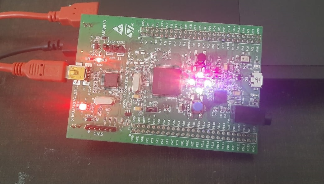
To flash the LED blinking firmware onto the STM32F4 Discovery Board, connect the board to your computer using a Mini USB cable plugged into the ST-LINK USB port (the one labeled CN1 on the top of the board, not the OTG port). The onboard ST-LINK/V2 programmer provides both programming and power — no external power supply is required.
In Keil uvision, open the project options (Project → Options for Target), go to the Debug tab, and select ST-Link Debugger. Then press F7 to build the project and F8 (Load) to flash the binary to the STM32F407VGT6. If the build succeeds and the flash operation completes without errors, all four onboard LEDs will immediately start blinking at 1 Hz.
Troubleshooting STM32F4 LED Blinking Issues
If you uploaded the code but the onboard LEDs of the STM32F4 Discovery Board are not blinking, one of these issues is almost certainly the cause:
- GPIO clock not enabled. If you forget
__HAL_RCC_GPIOD_CLK_ENABLE(), writes to the GPIO registers are ignored silently. Double-check this line is called beforeHAL_GPIO_Init(). - Wrong GPIO port. The onboard LEDs are on PORTD — not PORTA or PORTB. Make sure every reference in your init and toggle code uses
GPIOD. - Pin mode set to input. The default value of an uninitialized
GPIO_InitTypeDefis typically 0 (input). Always assignMode = GPIO_MODE_OUTPUT_PPexplicitly. - ST-LINK not detected. If Keil shows “No ST-LINK detected”, try a different USB cable — many Mini USB cables are charge-only with no data lines. The jumpers CN3 (labeled Discovery) must both be in place for the onboard ST-LINK to target the onboard MCU.
- Board resets repeatedly. Watchdog enabled accidentally or stack overflow. For this simple blink program, leave the default startup file untouched.
- Code compiles but LEDs stay off. You may have accidentally selected the wrong device (e.g., STM32F405 instead of STM32F407VG) in the target settings, causing the linker to use the wrong memory map.
Frequently Asked Questions
Which pins control the onboard LEDs on the STM32F4 Discovery Board?
The STM32F4 Discovery Board (STM32F407G-DISC1) has four user LEDs wired to pins PD12 (green, LD4), PD13 (orange, LD3), PD14 (red, LD5), and PD15 (blue, LD6) of PORTD on the STM32F407VGT6 microcontroller.
Why do I need to enable the GPIOD clock before blinking LEDs?
STM32 microcontrollers use clock gating to save power — every peripheral, including each GPIO port, has its clock disabled at reset. If you do not call __HAL_RCC_GPIOD_CLK_ENABLE() before HAL_GPIO_Init(), writes to the GPIOD registers silently do nothing and the LEDs will stay off even though your code appears correct.
What is the difference between HAL_GPIO_TogglePin() and HAL_GPIO_WritePin()?
HAL_GPIO_TogglePin() flips the current state of a GPIO pin in a single call — it is ideal for simple blink loops. HAL_GPIO_WritePin() drives the pin to an explicit state (GPIO_PIN_SET or GPIO_PIN_RESET) regardless of the previous state, which is more appropriate when you need exact control — for example in state machines, button-responsive code, or when you are mirroring the state of an external input.
Can I use this LED blinking code on the STM32 Nucleo or STM32 Blue Pill?
The HAL functions are identical across the STM32 families, but the onboard LED pin differs. On the STM32 Nucleo-F446RE the user LED is on PA5, and on the STM32 Blue Pill (STM32F103C8T6) the user LED is on PC13 (active low). Change the port, pin, and clock-enable macro accordingly and the same tutorial logic applies. We have dedicated guides for the STM32 Nucleo and STM32 Blue Pill for this reason.
Is the software delay in this tutorial accurate?
No — the Delay_ms() function used here is a crude busy-wait loop whose timing depends on the compiler’s optimization level and the clock configuration. For production code you should use HAL_Delay() (which is driven by SysTick) or a hardware timer. The busy-wait version is kept here only because it makes this first tutorial completely self-contained and free of SysTick setup.
Conclusion
You now have a fully working STM32F4 Discovery Board LED blinking project in Keil uvision using the HAL library. You installed the STM32F4 device pack, created a new Keil project, configured the GPIO HAL module, wrote and flashed the blink firmware, and learned how HAL_GPIO_Init(), HAL_GPIO_TogglePin(), and HAL_GPIO_WritePin() work internally. The same three-step pattern — enable the peripheral clock, fill an init struct, call the HAL init function — is the foundation for every other peripheral you will use on the STM32F407, from ADC and DAC to UART, SPI, and timers.
Related STM32F4 Discovery Board Tutorials
- Use Push Button to Control LEDs of STM32F4 Discovery Board – Digital Input Pins with HAL Driver
- ADC STM32F4 Discovery Board with HAL ADC Driver – Polling Method
- DAC STM32F4 Discovery Board – Generate Waveforms with Digital to Analog Converter
- UART/USART Communication STM32F4 Discovery Board – HAL UART Driver
i was searching for this detailed tutorial for a long time you resolved all problems thanks
Very nice explanation by you. It has resolved many of my doubts.
Thankyou so much for such wonderful tutorial.