automatic dark detection circuit with Alarm, dark detection circuit diagram and list of components of this project is given in this article. Automatic dark detection have many applications in students as well as industrial projects. In this article you can learn how to design automatic dark detection using analog electronics components like simple transistors, resistors and capacitors. I have also mentioned list of components along with circuit diagram of dark detection circuit.
What is automatic dark detection?
Automatic dark detection circuit sense light or intensity of light. Whenever light intensity falls below a minimum level, this circuit take actions to respond to any output. In this circuit a buzzer is connected at the output. When light falls below a minimum level, buzzer connected o output start producing beep. There are many applications of dark detector circuit. Some of them are given below:
- Automatic street light control
- Automatic intensity control of street lights
- Automatic lights control system in industry
- Protection against no light for security system based projects and many others.
Circuit diagram of automatic dark detection with Alarm:
Circuit diagram of this project is given below:
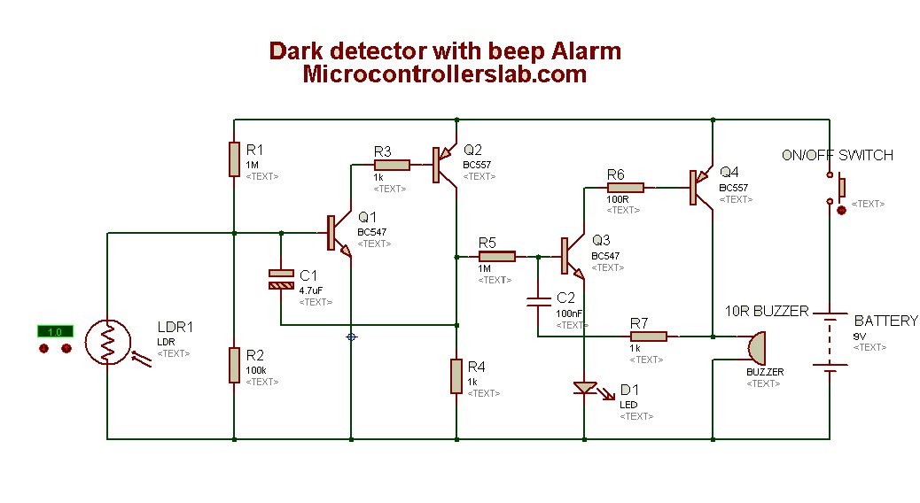
In above circuit diagram light dependent resistor is used a light sensor. Light dependent resistor works on the principle of resistance change. Whenever light falls on light dependent resistor, its resistance changes. When light intensity is high, resistance across LDR will be low, When light intensity is high, resistance across LDR terminals will be high.
Components list :
Category,Quantity,Reference,Value,Order Code
Resistors,2,"R1,R5",1M,
Resistors,1,"R2",100k,
Resistors,3,"R3,R4,R7",1k,
Resistors,1,"R6",100R,
Capacitors,1,"C1",4.7uF,
Capacitors,1,"C2",100nF,
Transistors,2,"Q1,Q3",BC547,
Transistors,2,"Q2,Q4",BC557,
Diodes,1,"D1",LED,
Miscellaneous,1,"BATTERY",9V,
Miscellaneous,1,"LDR1",LDR,
Miscellaneous,1,"ON/OFF SWITCH" Buzzer 10 ohm,,
Working of automatic dark detector circuit :
This circuit detects darkness with the help of light sensor and produce an alarming signal with the help of 10R buzzer. BC547 npn and BC557 pnp transistor form a emitter follower configuration to create high gain at the collector pin of BC557 transistor. Actually both pnp and npn transistors forms high gain amplifier to provide proper current to 10 ohm buzzer. Feedback for high gain amplifier is provided through 4.7uf capacitor. 9 volt battery is used to power this circuit and push button is used as switch in this project.
Thanks for reading this article Kindly share this circuit diagram with your classmates and friends.
What software do you use for this circuit?
From your article: “When light intensity is high, resistance across LDR will be low, When light intensity is high, resistance across LDR terminals will be high.”
This is a conflicting statement. Which half of your statement is true?
Hi John
Actually the statement is like this:
“When the light intensity is high, resistance across LDR will be low, When light intensity is low, resistance across LDR terminals will be high”
Thanks for pointing out, I will update the article.
Would this circuit continue to sound the alarm once the light has come back on?