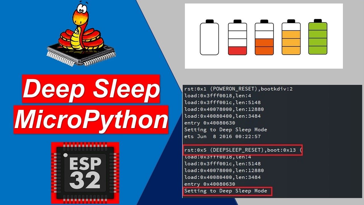
In this tutorial, we will learn about ESP32 deep sleep modes. In this comprehensive guide, we will look at ways to put the ESP32 development board into a deep sleep mode. Furthermore, We will also discuss different wake up sources through which ESP32 can go from sleep to normal execution mode such as timer, external events, etc. For the demo, we will explain it through three different examples.
In MicroPyhon, machine.deepsleep() function can be used to put ESP32 and ESP8266 into deep sleep mode.
We have a similar guide with ESP8266:

ESP8266 Deep Sleep and Wake Up Sources using MicroPython
Prerequisites
Before we start this lesson make sure you are familiar with and have the latest version of MicroPython firmware installed in your ESP boards and have a running Integrated Development Environment (IDE) in which we will be doing the programming such as uPyCraft IDE or Thonny IDE.
- Getting Started with uPyCraft IDE on ESP32 and ESP8266
- Getting Started with Thonny MicroPython IDE for ESP32 and ESP8266
ESP32 Operating Modes
ESP32 core provides five different operating mode as follows:
- Active mode
- Modem Sleep mode
- Light Sleep mode
- Deep Sleep mode
- Hibernation mode
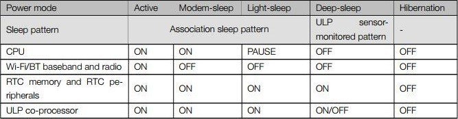
The following table lists which peripherals and units are either active or inactive during different modes. Maximum units remain in an inactive state in deep sleep and hibernation mode to save power consumption.
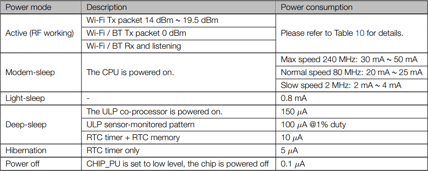
To see how these modes are useful in different applications, you can compare the power consumption of different operating modes listed in the table below:
What is Deep Sleep in ESP32?
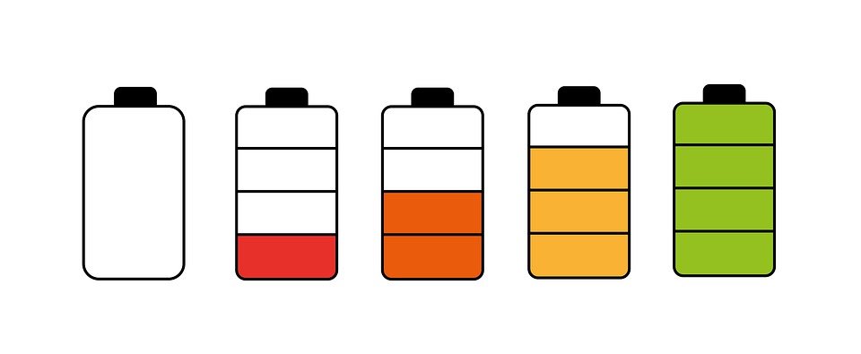
To reduce power consumption and save battery life, deep sleep mode is implemented in ESP32. Generally, the module is very power-hungry and may pull up 75mA in normal consumption or inactive mode.
But if WiFi is being used as well then the current consumption can go up to 240mA. Thus, if you are powering your ESP boards using batteries, it is not very convenient to use ESP32 in active mode when we want to perform some events after some specific duration only.
We can put the module into a deep sleep mode to reduce power consumption. When we have successfully activated deep sleep in ESP32, the current consumption would be in the range of micro Amperes (μA) and batteries will also last longer.
The table below shows the individual active units in ESP32 when it is set in deep sleep.
| Peripherals and Units | Active Units |
|---|---|
| ULP Co-processor | ON/OFF |
| RTC & RTC Peripherals | ON |
| ESP32 Core & Memory | OFF |
| Wi-Fi | OFF |
| Bluetooth | OFF |
| Peripherals | OFF |
| Radio | OFF |
As shown in the above table, during the deep sleep mode only the RTC (real-time clock) controller, RTC peripherals, and RTC memories are in active mode. All the digital peripherals, most of the RAM, and the CPU is powered off.
Because only the RTC module is active. Therefore, the data will be lost which was not initially present in the RTC recovery memory. The current consumption goes down to 0.15mA – 10 µA if the ULP co-processor is turned on.
ESP32 Wake Up Sources
After activating the deep sleep mode of ESP32, there are several ways in which the ESP board can be woken up such as:
- Time wake up
- External interrupt wake up
- Touch pin wake up
We’ll be focusing on two methods in this tutorial comprehensively. These are namely: Timer Wake up & External Wake up. We can also combine both of these sources together as well so whenever any one of them is triggered the ESP32 development board will wake up from deep sleep.
ESP32 Timer Wake Up
With timer wake up, we can put ESP32 into sleep mode and wake up.
The real-time controller (RTC) has a built-in timer. We have to set a predefined amount of time, after it is over, the built-in timer wakes up the chip from deep sleep mode. This is achieved through a function. We put the board in deep sleep mode for a specified amount of milliseconds.
We use the deepsleep() function which is available in the machine module. The deepsleep() function has a single argument that denotes the sleeping time in ms. For example:
machine.deepsleep(sleep_time_ms)Let’s have a look at a simple project demonstrating a timer wake up using an LED blinking. We are going to show you a simple demonstration of how to use a timer to wake up. We will blink an LED and ESP32 remains in the active mode for 10 seconds and after that time is over, ESP32 will go in to deep sleep. It will remain in deep sleep for 10 seconds. After that, it will again wakup and executes he same code.
MicroPython Code
In this example code, we put the ESP32 into a deep sleep for 10 seconds. It wakes up after 10 seconds and blinks an LED connected with GPIO2 and goes back to deep sleep again for 10 seconds.
import machine
from machine import Pin
from time import sleep
led = Pin (2, Pin.OUT)      #GPIO14 as output for LED
led.value(1)                 #LED is ON
sleep(1)                     #delay of 1 second
led.value(0)                 #LED is OFF
sleep(1)                     #delay of 1 second

# add a 10 second delay before ESP32 goes into deep sleep mode.
# it is just see the message on serial console
# You should remove this line in your real microPython project script

sleep(10)                    #delay of 10 seconds
print('Setting to Deep Sleep Mode')
machine.deepsleep(10000)     #10000ms sleep time
How the Code Works?
First, we start by importing the machine module, Pin class from the machine module, and sleep class from the time module. This is necessary because we want to use deep sleep mode as well as wake up ESP32 from a deep sleep.
import machine
from machine import Pin
from time import sleep
The next step is where we will be blinking the built-in LED on the ESP32 development board. We create an “led” object and set the built-in LED as an output on the pin. The GPIO2 is the pin location where the built-in Led which we want to access is internally connected. Then we will access the led object’s value and pass 1 for led ON and 0 for led OFF as the parameters. We will also be using a delay of 1 second between each transition so we are able to see the blinking effect.
led = Pin(14, Pin.OUT)      #GPIO14 as output for LED
led.value(1)                 #LED is ON
sleep(1)                     #delay of 1 second
led.value(0)                 #LED is OFF
sleep(1)                     #delay of 1 second
For more information on how to use GPIO pins of ESP32 in MicroPython, you can read these in-depth gudies:
- ESP32 and ESP8266 GPIO Programming with MicroPython – LED Blinking Example
- Push Button with ESP32 and ESP8266 using MicroPython – Control an LED
The next step is very crucial. We will be incorporating a delay of 10 seconds ( sleep(10)) after the Led has gone from the ON to OFF transition once. This delay will help in establishing a serial communication when the ESP board is awake (before putting it in deep sleep). To upload newer pieces of program code, the board has to be awake. Hence, we will also print “Setting to Deep Sleep Mode” on the screen to specify that we will be entering the deep sleep mode shortly.
sleep(10)        #delay of 10  seconds
print('Setting to Deep Sleep Mode')
The final step is initiating the deepsleep() function from the machine module. We will be setting it to sleep for 10000ms which is 10 seconds. After the 10 seconds are over, the ESP board would wake up and restart.
machine.deepsleep(10000) #10000ms sleep time
Note: If you call deepsleep() without argument inside your code, it will put the ESP32 into deep sleep indefinitely.
Demonstration
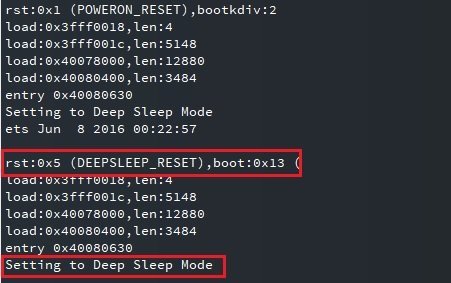
Create a new file in uPyCraft or Thonny IDE and give it a main.py name. After that upload the file to the ES32 board and click on the reset/enable button:

You will see that the ESP32 will blink onboard LED once and remains in the active mode for 10 seconds. After that, it will print a message “Setting to Deep Sleep Mode” and then it goes into deep sleep mode.
ESP32 External Wake Up from Deep Sleep
As discussed earlier, we can also use an external interrupt to wake up ESP32 from a deep sleep. There is two external wake up resources available such as an ext0 and ext1.
External Wake up is the second type of wake-up method which we will be covering. When the state of a GPIO pin is changed, the ESP board will wake up from deep sleep. There are two types of external wake-ups in the ESP32.
- ext0: This is used when a single GPIO pin is being accessed.
- ext1: This is used when several GPIO pins are being accessed e.g. through different push buttons.
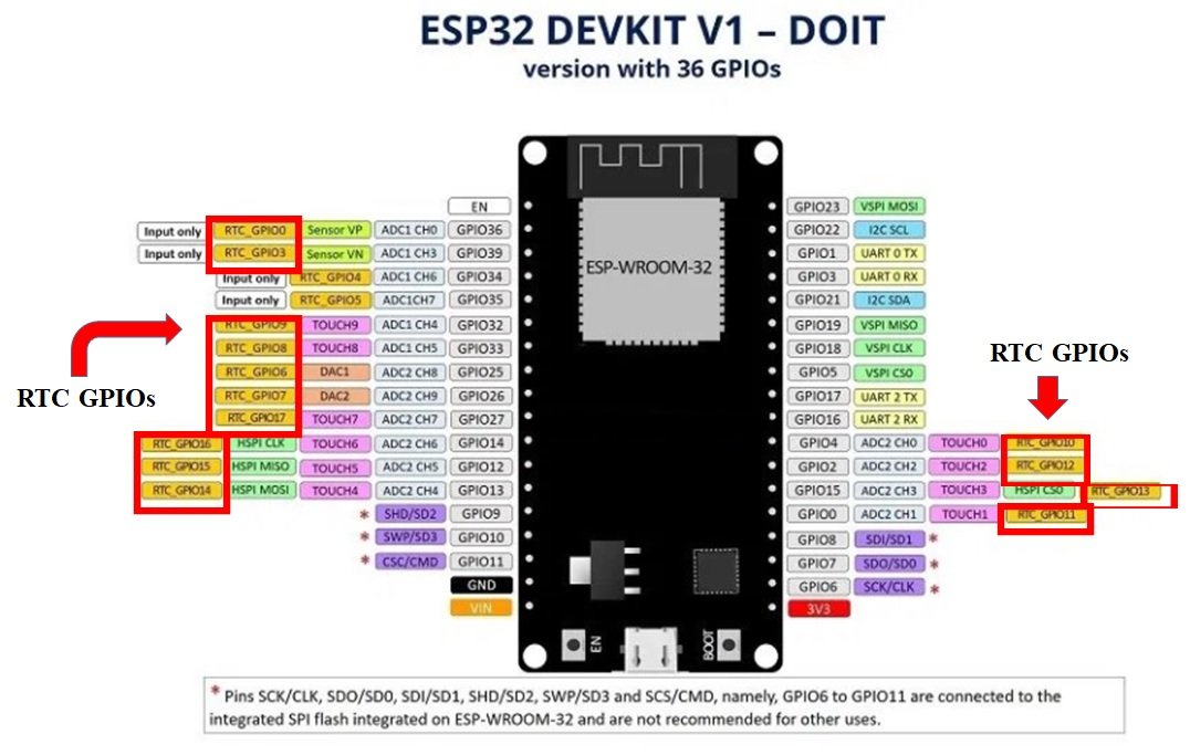
Note: Only Real-time clock or RTC input-output pins can be used as a wake up source. Therefore, to make use of this external wake up we need to make sure that during the deep sleep, the RTC peripherals are powered ON. Thus, we can only use the RTC GPIOs to induce the ext0, ext1 external wake-up.
The figure below shows the GPIO pinout which we can use, highlighted in red:
For more details on EPS32 pinout, check this:
For ESP32 Devkit V1- DOIT we can use the following 14 GPIO pins:
- RTC_GPIO0 : GPIO36
- RTC_GPIO3: GPIO39
- RTC_GPIO9: GPIO32
- RTC_GPIO8: GPIO33
- RTC_GPIO6: GPIO25
- RTC_GPIO7: GPIO26
- RTC_GPIO17: GPIO27
- RTC_GPIO16: GPIO14
- RTC_GPIO15: GPIO12
- RTC_GPIO14: GPIO13
- RTC_GPIO11: GPIO0
- RTC_GPIO13: GPIO15
- RTC_GPIO12: GPIO2
- RTC_GPIO10: GPIO4
External Wake Up – ext0
In this section, we will see how to configure and use external wake up as a source to exit deep sleep mode.
The esp32.wake_on_ext0(pin, level) function defines how ext0 wakes up ESP32 from deep sleep.
Instantiating ext0 External Wake Up in ESP32
To configure ext0 for ESP32 using MicroPython, follow the steps as follows:
- Importing the ESP32 module to set a pin as a wake-up source
- Defining a wake-up pin from the RTC GPIO pins stated above
- Lastly, we use the wake_on_ext0() method to configure ext0 as a wake-up source.
wake_on_ext0() Function
The wake_on_ext0() function takes the following parameters:
The first argument is the RTC GPIO pins. This is the object which denotes the GPIO which would be set up as the wake-up source. Additionally, the last argument is the trigger level. This trigger level defines the state of the GPIO pin as a source of wake up. It can be one of the following types:
- WAKEUP_ANY_HIGH: Wake up process is triggered when the GPIO is in a high state.
- WAKEUP_ALL_LOW: Wake up process is triggered when the GPIO is in a low state.
In short, the wake_on_ext0() method defines in the following way:
ESP32.wake_on_ext0(pin = wakeup_source, level = ESP32.WAKEUP_ANY_HIGH)ext0 Example
Now, we are going to demonstrate how we will be using ext0 as an external wake up with the help of a push-button. The push button will act as a wake-up source for the ESP board. We will need the following components.
Required Components
- ESP 32 Devkit board
- One Push button
- One 10k ohm resistor
- Breadboard
- Connecting Wires
Schematic
Assemble the following components with ESP32 as shown in the schematic diagram below:
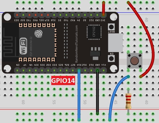
As we can see from the diagram, we connect the push button with any RTC GPIO pin which was stated above. We have used GPIO14 for this purpose. The 10k ohm pull-down resistor is also connected and grounded. One terminal of the push button is powered by 3.3 V and the other one is connected with GPIO14 to sense a change in logic level.
MicroPython Script
import machine           #importing modules
import esp32
from machine import Pin
from time import sleep

# check if the device woke from a deep sleep
if machine.reset_cause() == machine.DEEPSLEEP_RESET:
  print('woke up from a deep sleep')


push_button = Pin(14, mode = Pin.IN)     #setting push_button as wake up source
esp32.wake_on_ext0(pin = push_button, level = esp32.WAKEUP_ANY_HIGH)  #initializing wake up

#**ADD YOUR MAIN CODE HERE**/

print('I am in active Mode for 10 seconds')
sleep(10)                      #delay of 10s
print('Going to Deep Sleep Mode')
machine.deepsleep()               #module goes in deep sleep
How Does the Code Work?
As always, the first step is to import the different modules which we would be using. Therefore, we will import the esp32, machine, and time module. We will then import the pin and the sleep class from their respective modules.
import machine           #importing modules
import esp32
from machine import Pin
from time import sleep
We can find the source of reset by using machine.reset_cause() function. If reset is caused by machine.reset_cause(), it will return true.The following code snippet can be used to check if the reset is caused by deep sleep.
# check if the device woke from a deep sleep
if machine.reset_cause() == machine.DEEPSLEEP_RESET:
  print('woke up from a deep sleep')
Next, we will set a GPIO pin object as a wake-up source. We have set it as the variable ‘wakeup_source.’ We will be using the Pin object and specify its arguments as the GPIO PIN which is 14 in our case and will set it as an input.
push_button = Pin(14, mode = Pin.IN) #setting push_button as wake up source
The next line initializes the wake_on_ext0() method. We set the pin which is the GPIO pin connected with the wake-up source as ‘push_button’ and the level as ‘ESP32.WAKEUP_ANY_HIGH’ because we want to trigger the wake-up process when the state of the push button is high.
esp32.wake_on_ext0(pin = push_button, level = esp32.WAKEUP_ANY_HIGH) #initializing wake upAfter we have defined our wake-up source which is the push button we can write our main code and after that induce the deep sleep mode. We will be adding a 10-second delay and then will go into a deep sleep by using the machine.deepsleep().
print('I am in active Mode for 10 seconds')
sleep(10)                      #delay of 10s
print('Going to Deep Sleep Mode')
machine.deepsleep()               #module goes in deep sleep
Demonstration
Create a new file in uPyCraft or Thonny IDE and give it a main.py name. After that upload the file to the ES32 board and click on the reset/enable button:
You can see that on POWERON_RESET, you will not see that message “woke up from a deep sleep” on the shell console. Because no wake up source is the source of reset. After that, ESP32 remains in the active mode for 10 seconds and goes to deep sleep mode as soon as 10 seconds elapsed.
But as soon as we press the push button, you will see the message “woke up from a deep sleep” on the shell console. Because this time, the cause of the reset is ext0 wake up.

External Wake up: ext1
The esp32.wake_on_ext1(pins, level) function defines how ext1 wakes up ESP32 from deep sleep.
Now let’s have a look at ext1. This is used when we want to have more than one GPIO pin as a source to initiate the external wake-up. Only the RTC controller is powered on during deep sleep. Therefore, we can only RTC GPIOs and we have defined the RTC GPIOs in the last section.
To configure ext1 in MicroPython we follow these steps:
- Importing the ESP32 module to set a pin as a wake-up source
- Defining a wake-up pin from the RTC GPIO pins stated above.
- Lastly, we will be using the wake_on_ext1() method to configure ext1 as multiple wake-up sources.
wake_on_ext1() Function
The wake_on_ext1() method takes on the following parameters:
The first argument is a tuple/list of valid Pin objects. This is the object which denotes the GPIOs which would be set up as the wake-up sources. The second argument is the level. This level shows the state of the GPIO pin. It can be one of the following:
- WAKEUP_ANY_HIGH: Wake up process is triggered when ANY GPIO is in a high state.
WAKEUP_ALL_LOW: Wake up process is triggered when ALL the GPIO is in a low state.
Thus, the wake_on_ext() method is defined in the following way.
ESP32.wake_on_ext1(pin = wakeup_source, level = ESP32.WAKEUP_ANY_HIGH)ext1 Example
Now we are going to demonstrate how we will be using ext1 external wake-up with the help of two push buttons. We can use as many as we want, but to keep it simpler we will work with only 2 for now. The push buttons will act as wake up sources for the ESP board. We will be needing the following components.
Required Components
- ESP 32 Devkit board
- Two Push button
- Two 10k ohm resistor
- Breadboard
- Connecting Wires
Schematic Diagram
Assemble the following components with ESP32 as shown in the schematic diagram below:
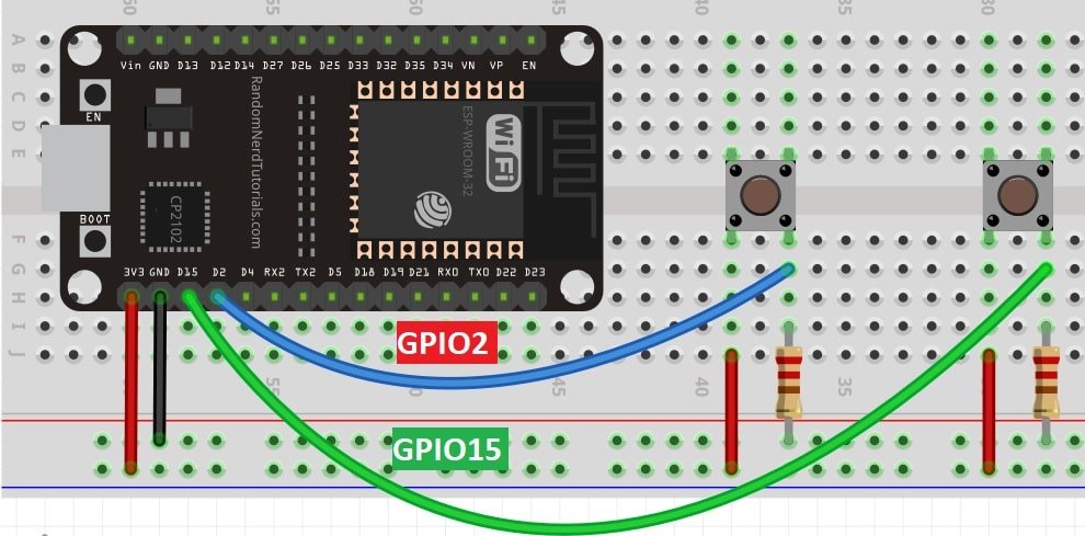
As we can see in the schematic both terminals of the push buttons have been commonly grounded through the two resistors and connected through GPIO2 and GPIO15. The other terminal for both is powered through 3.3V.
MicroPython Script
The following MicroPython script uses GPIO2 and GPIO15 as a wake up source for ext1. However, you can use more than 2 RTC GPIOs also.
import machine           #importing modules
import esp32
from machine import Pin
from time import sleep

# check if the device woke from a deep sleep
if machine.reset_cause() == machine.DEEPSLEEP_RESET:
  print('woke up from a deep sleep')


push_button1 = Pin(2, mode = Pin.IN)  #setting push_button1 as wake up source
push_button2 = Pin(15, mode = Pin.IN)  #setting push_button2 as wake up source

esp32.wake_on_ext1(pins = (push_button1, push_button2), level = esp32.WAKEUP_ANY_HIGH)   #initializing ext1

#**ADD YOUR MAIN CODE HERE**/

print('I am in active Mode for 10 seconds')
sleep(10)                      #delay of 10s
print('Going to Deep Sleep Mode')
machine.deepsleep()               #module goes in deep sleep
How Does the Code Work?
The program code is similar to the one we looked at before: ext0. In this example, we used ext1. After importing the relevant modules and classes, we would set the two GPIO pins for the wake up sources namely push_button1 and push_button2, and configure them as inputs.
push_button1 = Pin(2, mode = Pin.IN)  #setting push_button1 as wake up source
push_button2 = Pin(15, mode = Pin.IN)  #setting push_button2 as wake up source
The next line initializes the wake_on_ext1() method. We set two GPIOs as the wake up sources ‘push_button1’ and ‘push_button2’ and the level as ‘ESP32.WAKEUP_ANY_HIGH’. Because we want to trigger the wake up process when the state of any push button is high. That means whenever any push button is pressed, the ESP32 would wake up from deep sleep.
esp32.wake_on_ext1(pins = (push_button1, push_button2), level = esp32.WAKEUP_ANY_HIGH) #initializing ext1
After we have defined our wake up sources, we can write our main code and after that induce the deep sleep mode. For the demo, we will be adding 10 seconds delay and then put ESP32 into a deep sleep by using machine.deepsleep().
print('I am in active Mode for 10 seconds')
sleep(10)                      #delay of 10s
print('Going to Deep Sleep Mode')
machine.deepsleep()               #module goes in deep sleep
ESP32 Touch Pins Wake Up
ESP32 has touch sensitive pins which can sense the variations in electrical charge whenever someone touch those pins. We can also configure them as source of wake up for ESP32 from deep sleep.
The esp32.wake_on_touch(wake)
You can find more information on ESP32 touch sensitive pins here:
The esp32.wake_on_touch(wake) configure touch pins as a wake up source. It takes a boolean value as an input argument. Passing TRUE will enable the touch-sensitive pins as a wake up and passing FALSE will disable the touch pins as a source of wake up from deep sleep.
from machine import Pin, TouchPad, deepsleep
import time
import esp32

wake = Pin(14, mode = Pin.IN)
touch = TouchPad(wake)
touch.config(500)
esp32.wake_on_touch(True)

time.sleep(5)
deepsleep(5000)
You can also read these MicroPython tutorials and projects:
- OLED Display with ESP32 and ESP8266 in MicroPython
- MicroPython: Wi-Fi Manager with ESP32 and ESP8266
- MPU-6050 with ESP32/ESP8266 (Accelerometer, Gyroscope, and temperature)
- MicroPython: BME680 Web Server with ESP32 and ESP8266 (Gas, Pressure, Temperature, Humidity)
- Send Sensor Readings via Email (IFTTT) with ESP32 and ESP8266
Thank you for this tutorial. The ESP-IDF provides a function called “esp_sleep_get_wakeup_cause()” which allows us to determine whether or not we woke up from deepsleep due to an interrupt or due to a timer. Is this function available in micropython? If so, it would be good to see it demonstrated in this article. If not, it would be good to see this limitation explained in this article.
To answer my own question, this can be done by checking the value of “machine.wake_reason()”. Here’s some sample code to display the wake reason:
reason = machine.wake_reason()
print(‘Wake reason:’, reason)
print(‘EXT0_WAKE:’, reason == machine.EXT0_WAKE)
print(‘EXT1_WAKE:’, reason == machine.EXT1_WAKE)
print(‘PIN_WAKE:’, reason == machine.PIN_WAKE)
print(‘TIMER_WAKE:’, reason == machine.TIMER_WAKE)
print(‘TOUCHPAD_WAKE:’, reason == machine.TOUCHPAD_WAKE)
print(‘ULP_WAKE:’, reason == machine.ULP_WAKE)