In this tutorial, you will learn to interface a 16×2 LCD with TM4C123 Tiva C Launchpad. As you know that 16×2 LCD is widely used in embedded projects to display different types of sensor data. Firstly, we will discuss the pinout of LCD and its connection diagram with Tiva Launchpad. After that, we will discuss the 16×2 LCD driver for TM4C123 Tiva Launchpad using Keil uvision IDE.
Pre-requisites:
- How to Download and Install Keil uVision for ARM and 8051
- Getting started with Keil uVision: Write your first Program for Tiva LaunchPad
Recommended Components
The following components are used in this project or are helpful for getting started with TM4C123 Tiva C LaunchPad development.
| Component | How it’s used in this project | Buy on Amazon |
|---|---|---|
| TM4C123G Tiva C LaunchPad | The Tiva C board that drives the 16×2 LCD in 4-bit mode. | Check Price |
| Micro USB Cable | Connects the LaunchPad’s onboard debugger to your PC for programming and power. | Check Price |
| 16×2 LCD | The character display being interfaced in this project. | Check Price |
| 10kΩ Potentiometer | Adjusts the LCD contrast via the Vo pin. | Check Price |
| Breadboard | Solderless breadboard for building the circuit. | Check Price |
| Jumper Wires | For wiring the LCD and potentiometer to the LaunchPad. | Check Price |
As an Amazon Associate we earn from qualifying purchases. Prices and availability are accurate as of the date/time indicated and are subject to change.
16×2 LCD Introduction
This LCD can display 32 ASCII characters. It consists of two rows and one column. Each row can display one ASCII character. Hence, the position of each character is defined in terms of rows and columns order pairs (x,y). For example, (0,0) means the first row and first column, and (1,15) means the second row and 15th column.
Pinout Diagram
Following diagram shows the pinout diagram of 16×2 LCD.
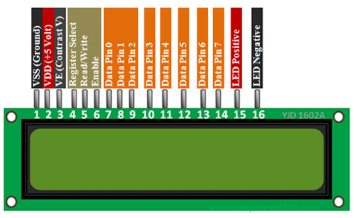
16×2 LCD Pin Details
Let’s first discuss the pin details of LCD. It consists of 16 pins such as data, control, power supply, and backlight LED pins.
Data Pins
Pins D0 to D7 are data pins which are used to send data to be displayed or commands to LCD controller. Hence, these lines will be connected with TM4C123 GPIO pins to transfer data. But this LCD can be used either in 4-bit (only D0 to D3 pins are used) or 8-bit mode( all D0 to D7 pins are used).
Control Pins
LCD Contrast (Vo) : It is used to adjust the contrast of LCD with respect to text display. This contrast can be set through by using a potential divider circuit with a variable resistor.
Register Select (RS) : With the help of this pin, TM4C123 microcontroller informs the LCD controller either we are sending commands or data to LCD. In other words, it helps to differentiate between data and commands.
For example, when we want to send commands to LCD from TM4C123 microcontroller, we set this pin active low by sending an active signal from the GPIO pin of Tiva Launchpad. These commands are setting cursor position, cursor on or off, scrolling text left or right, clearing text from LCD, etc. On the contrary, when we want to send data to LCD, we provide active high signal to this pin from TM4C123 microcontroller
Read/Write (R/W)
As its name suggests, R/W is used to select read or write mode of LCD. When this pin is set to active high, LCD will be in read mode which means we can read data from the LCD. Similarly, when this pin is set to active low, we will be able to write data to the LCD. We will connect this pin to the ground. Because we are using a 16×2 LCD as an output device only.
Enable (E)
This pin is used to enable and disable LCD. When this pin is active low, LCD controller will be disabled. That means control pins and data pins will not have any effect on the display. On the other hand, when the enable pin is set to active high, the LCD will work normally and process all data and control instructions.
Backlight LED Pins
These pins are cathode and anode pins of back light LED. They are used to provide +5 volts and ground to anode and cathode pins.
Power Supply Pins
+5 volt power supply pins.
Difference Between 4-bit and 8-bit mode
HD47780 LCDs can be interfaced with TM4C123 Tiva Launchpad either in 4-bit or 8-bit mode. For a 4-bit interface, we need to use 6 GPIO pins of Launchpad. In 4-bit mode, data transfers from microcontroller to the LCD in two consecutive half bytes. On the contrary for 8-bit mode, one byte data transfers to the LCD in one go. Consequently, we need to use 10 GPIO pins of TM4C123 microcontroller. Therefore, to save GPIO pins, we will use 4-bit mode of 16×2 LCD. Because, displaying data on LCD is not a time-critical action. Hence. 4-bit use will save us 4 GPIO pins of the Tiva launchpad.
16×2 LCD Commands
The following table lists some of the most commonly used commands which are used to configure and control LCD. You can consult the datasheet of the 16×2 controller to know about more commands. As we mentioned earlier, the RS should be made active low to send commands to LCD using D0-D7 data lines.
In the later section of this tutorial, we will see how to send commands from TM4C123 Tiva Launchpad to LCD.
| Command | Function |
|---|---|
| 0x01 | Clear display screen |
| 0x02 | Return cursor to home i.e starting position |
| 0x06 | Shift the cursor one position right |
| 0x0F | Turn on LCD display |
| 0x80 | Takes cursor to beginning of first row |
| 0xC0 | Takes cursor to beginning of Second row |
| 0x28 | Select 4-Bit Mode of LCD |
| 0x38 | Select 8-Bit Mode of LCD |
Note: HD47780 controller which is connected with a 16×2 display works at very low speed than our TM4C123 microcontroller. Therefore, in order to synchronize the HD47780 controller with our microcontroller, we should add some delay between sending consecutive commands to LCD. We will see in the programming part how to do it.
LCD Interfacing with TM4C123 Tiva Launchpad in 4-bit Mode
As we mentioned earlier, we will use a 4-bit mode to interface 16×2 LCD with TM4C123 microcontroller. Now make the connection with 16×2 LCD with TM4C123 Tiva C Launchpad according to this schematic diagram.
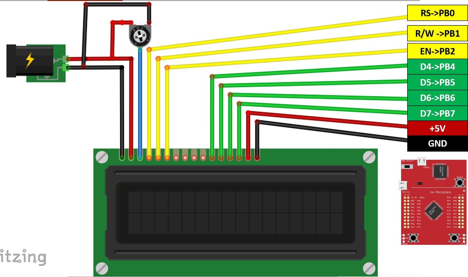
In this schematic, we use GPIO PORTB of TM4C123GH6PM microcontroller to send commands and data to the LCD. PB0 to PB2 pins are used to provide control signals such as RS, E, and R/W. Similarly, PB4-PB7 pins are used to send data. Also, connect a potentiometer with a contrast adjust pin. Connect +5 volts and ground to other terminals of the potentiometer.
16×2 LCD Programming with TM4C123 Microcontroller
Now let’s see how to send commands and data to the 16×2 LCD from TM4C123 Tiva C Launchpad. Firstly, we will write functions to send commands, data and initializations of the display controller.
Write 4-bit Nibble to LCD
As we mentioned earlier, we will be using 16×2 LCD in 4-bit mode. Therefore, first we need to create a function to send data or commands to LCD in 4-bit mode. This LCD_Write_Nibble() routine is used to send a nibble. The same function works for both data and commands. The second argument (unsigned char control), which is a RS signal for LCD, differentiates between data or command. Because when we want to send data we set RS to active high and when we want to send commands we clear the RS signal.
Inside this function, for data to be transmitted to D0-D3 pins, first we extract the upper bits from the data input argument. Because LCD data pins are connected to the PB4-PB7 pins of TM4C123 microcontroller. After that, we extract the lower bits from the data input argument. Because LCD control pins are connected to the PB0-PB2 pins of TM4C123 microcontroller.
In order to perform a write operation, first, we make the RS and R/W pins active low. After that, we give an active high to low transition pulse to enable pin to perform a write operation on the LCD. Finally, send nibble to LCD.
void LCD_Write_Nibble(unsigned char data, unsigned char control)
{

    data &= 0xF0;       /* Extract upper nibble for data */
    control &= 0x0F;    /* Extract lower nibble for control */
    LCD->DATA = data | control;       /* Set RS and R/W to zero for write operation */
    LCD->DATA = data | control | EN;  /* Provide Pulse to Enable pin to perform wite operation */
    delay_us(0);
    LCD->DATA = data; /*Send data */
    LCD->DATA = 0; /* stop writing data to LCD */
}
LCD Commands Send Function
This function is used to send commands to LCD. All commands are of 8-bits. Hence, first this routine sends the upper nibble of command to LCD and after that it sends the lower nibble. As we mentioned, the HD77480 controller operates at much lower speed than the TM4C123 microcontroller. Therefore, we need to add delay between sending commands. Command 1 and 2 takes 1.64ms and all other commands take 40us. Therefore, we add a delay of 2ms if commands are less than 4 and 40us for all other commands.
void LCD_Cmd(unsigned char command)
{
    LCD_Write_Nibble(command & 0xF0, 0);   /* Write upper nibble to LCD */
    LCD_Write_Nibble(command << 4, 0);     /* Write lower nibble to LCD */

    if (command < 4)
        delay_ms(2);         /* 2ms delay for commands 1 and 2 */
    else
        delay_us(40);        /* 40us delay for other commands */
}
LCD Initialization Function
To initialize LCD, first we need to configure PORTB GPIO pins as digital output pins. We have already posted an in-depth guide on how to use GPIO pins of Tiva launchpad. You can read this guide:
LCD_init() routine enables the clock to TM4C123 GPIOB which is connected to control and data pins of 16×2 LCD. After we send various initialization commands to LCD from control pins of TM4C123 microcontroller such as:
- Set the character font size to 5×7. Because fonts on 16×2 LCD can be used in different sizes such as 5×7, 5×10 ang 5xn. Here 5 represents the number of rows and n represents the number of columns.
- Select 4-bit Mode to transfer data or commands in two nibbles
- Setting to move cursor position right after displaying each character
- Clear the screen
- Enable light and Cursor blinking
/* LCD and GPIOB initialization Function */
void LCD_init(void)
{
 SYSCTL->RCGCGPIO |=(1<<1); /* Enable Clock to GPIOB */
 LCD->DIR |=0xFF; /* Set GPIOB all pins a digital output pins */
 LCD->DEN |=0xFF; /* Declare GPIOB pins as digital pins */

 LCD_Cmd(Set5x7FontSize);  /* select 5x7 font size and 2 rows of LCD */
 LCD_Cmd(Function_set_4bit); /* Select 4-bit Mode of LCD */
 LCD_Cmd(moveCursorRight); /* shift cursor right */
 LCD_Cmd(clear_display); /* clear whatever is written on display */
 LCD_Cmd(cursorBlink);  /* Enable Display and cursor blinking */

}
LCD Write Character Function
LCD_Write_Char() function prints a character on the current cursor position of the display. A character type of data consists of 8-bits. But we are using a 4-bit mode of LCD. Hence, data transfers in two nibbles or 2 pieces of 4-bits by using LCD_nibble_write() function. The one important point to note here is that we are sending control signal RS which will be defined as an active high micro in the code. Because we set RS signal to active high when we want to transmit data from TM4C123 Tiva Launchpad to LCD.
void LCD_Write_Char(unsigned char data)
{
    LCD_Write_Nibble(data & 0xF0, RS);    /* Write upper nibble to LCD and RS = 1 to write data */
    LCD_Write_Nibble(data << 4, RS);      /* Write lower nibble to LCD and RS = 1 to write data */
    delay_us(40);
}
LCD String Write Function
LCD_String() routine writes string to LCD starting from current cursor position. It uses LCD_Write_Char() function to send all characters of a string one by one. LCD_Write_Char() function keeps writing characters till the NULL character is found.
void LCD_String (char *str)	/* Send string to LCD function */
{
	int i;
	for(i=0;str[i]!=0;i++)  /* Send each char of string till the NULL */
	{
		LCD_Write_Char(str[i]);  /* Call LCD data write */
	}
}
Complete Code
This sample code of TM4C123 Tiva C Launchpad prints characters and strings on 16×2 LCD. It is written in Keil uvision but you can port it to other IDEs of your choice also. If you don’t know how to use Keil uvision, you can check these getting starting guides:
This code prints character ‘A’ on first row and first column of LCD.
#include "TM4C123.h" /* include register defintion file of TM4C123GH6PM */
#define LCD GPIOB   /* Define "LCD" as a symbolic name for GPIOB */
#define RS 0x20 /* PORTB BIT5 mask */
#define RW 0x40 /* PORTB BIT6 mask */
#define EN 0x80 /* PORTB BIT7 mask */
#define HIGH 1
#define LOW 0

/*define useful symbolic names for LCD commands */
#define clear_display     0x01
#define returnHome        0x02
#define moveCursorRight   0x06
#define moveCursorLeft    0x08
#define shiftDisplayRight 0x1C
#define shiftDisplayLeft  0x18
#define cursorBlink       0x0F
#define cursorOff         0x0C
#define cursorOn          0x0E
#define Function_set_4bit 0x28
#define Function_set_8bit 0x38
#define Entry_mode        0x06
#define Function_8_bit    0x32
#define Set5x7FontSize    0x20
#define FirstRow          0x80

/* prototypes of LCD functions */
void delay_ms(int n); /* mili second delay function */
void delay_us(int n); /* micro second delay function */
void LCD_init(void);  /* LCD initialization function */
void LCD_Cmd(unsigned char command); /*Used to send commands to LCD */
void LCD_Write_Char(unsigned char data); /* Writes ASCII character */
void LCD_Write_Nibble(unsigned char data, unsigned char control); /* Writes 4-bits */
void LCD_String (char *str);	/* Send string to LCD function */


int main()
{
 LCD_init();
 LCD_Cmd(clear_display);
 LCD_Cmd(FirstRow); /* Force cusor to begining of first row */
 delay_ms(500);

 LCD_Write_Char('A');
 delay_ms(500);

}

/* LCD and GPIOB initialization Function */
void LCD_init(void)
{
 SYSCTL->RCGCGPIO |=(1<<1); /* Enable Clock to GPIOB */
 LCD->DIR |=0xFF; /* Set GPIOB all pins a digital output pins */
 LCD->DEN |=0xFF; /* Declare GPIOB pins as digital pins */

 LCD_Cmd(Set5x7FontSize);  /* select 5x7 font size and 2 rows of LCD */
 LCD_Cmd(Function_set_4bit); /* Select 4-bit Mode of LCD */
 LCD_Cmd(moveCursorRight); /* shift cursor right */
 LCD_Cmd(clear_display); /* clear whatever is written on display */
 LCD_Cmd(cursorBlink);  /* Enable Display and cursor blinking */

}

void LCD_Cmd(unsigned char command)
{
    LCD_Write_Nibble(command & 0xF0, 0);   /* Write upper nibble to LCD */
    LCD_Write_Nibble(command << 4, 0);     /* Write lower nibble to LCD */

    if (command < 4)
        delay_ms(2);         /* 2ms delay for commands 1 and 2 */
    else
        delay_us(40);        /* 40us delay for other commands */
}


void LCD_Write_Nibble(unsigned char data, unsigned char control)
{

    data &= 0xF0;       /* Extract upper nibble for data */
    control &= 0x0F;    /* Extract lower nibble for control */
    LCD->DATA = data | control;       /* Set RS and R/W to zero for write operation */
    LCD->DATA = data | control | EN;  /* Provide Pulse to Enable pin to perform wite operation */
    delay_us(0);
    LCD->DATA = data; /*Send data */
    LCD->DATA = 0; /* stop writing data to LCD */
}
void LCD_Write_Char(unsigned char data)
{
    LCD_Write_Nibble(data & 0xF0, RS);    /* Write upper nibble to LCD and RS = 1 to write data */
    LCD_Write_Nibble(data << 4, RS);      /* Write lower nibble to LCD and RS = 1 to write data */
    delay_us(40);
}


void LCD_String (char *str)	/* Send string to LCD function */
{
	int i;
	for(i=0;str[i]!=0;i++)  /* Send each char of string till the NULL */
	{
		LCD_Write_Char(str[i]);  /* Call LCD data write */
	}
}

/* Mili seconds delay function */
void delay_ms(int n)
{
 int i,j;
 for(i=0;i<n;i++)
 for(j=0;j<3180;j++)
 {}
}

/* Micro seconds delay function */
void delay_us(int n)
{
 int i,j;
 for(i=0;i<n;i++)
 for(j=0;j<3;j++)
 {}

}
Conclusion
In this tutorial, we’ve explored the process of interfacing a 16×2 LCD with the TM4C123 Tiva C Launchpad, a common setup for displaying sensor data in embedded systems. We started by examining the LCD’s pinout and connection diagram to the Tiva Launchpad, ensuring a solid understanding of the hardware setup. Following this, we delved into the development of a 16×2 LCD driver using the Keil uVision IDE, providing practical insights into configuring and managing the LCD display. By the end of this tutorial, you should have a comprehensive grasp of both the hardware connections and software implementation necessary for integrating a 16×2 LCD into your embedded projects.
Other TM4C123 Tutorials:
- SPI Communication TM4C123
- PWM TM4C123
- HC-SR04 Ultrasonic Sensor Interfacing with TM4C123
- TM4C123 Timer as a Counter in Input-Edge Count Mode
- Frequency Measurement using TM4C123 Timers in Input-Edge Capture Mode
- TM4C123 Timer in Input Edge Time Mode
- Timer Interrupt TM4C123
- Interrupt Processing ARM Cortex-M Microcontrollers
Other 16×2 LCD tutorials:
- 16×2 LCD Interfacing with PIC Microcontroller
- I2C LCD interfacing with ESP32 and ESP8266 in Arduino IDE
- LCD interfacing with MSP430 LaunchPad
- Scrolling text on LCD using MSP430 microcontroller
- LCD Interfacing with Arduino UNO R3
- Display GPS Co-ordinates on LCD using pic microcontroller
- INTERFACING LCD WITH 8051 MIROCONTROLLER with code
Very use full. I am searching this Thanks
Hi,i followed exactly the same as you did,i watched in the debug view,the data is written successfully,but there’s no data showing up in LCD,i spent so much time on it now,if you could point out some direction,it would be super helpful.
Thanks in advance.
——Willy
how can you see data in debug
while debugging this code
void delay_ms(int n)
{
int i,j;
for(i=0;i<n;i++)
for(j=0;j<3180;j++)
{}
}
in the void delay us it enters the loop and doesnot exit it
You need to step over to exit this.
Hi, I don’t understand. You set them in higher nibble
#define RS 0x20 /* PORTB BIT5 mask */
#define RW 0x40 /* PORTB BIT6 mask */
#define EN 0x80 /* PORTB BIT7 mask */
And then:
control &= 0x0F; /* Extract lower nibble for control *