A diode is a basic PN junction semiconductor device well-known in the microelectronics world. Because it is constructed with P and N-type materials. It acts as a one-way switch that allows the current to flow in one direction and halts in the other direction.
1N4007 belongs to the silicon family of1N400X series. It is a general-purpose rectifying diode that serves its purpose of converting alternating current signals(AC) to direct current signals (DC) in electronic products.
This tutorial will discuss its pinout, features, specifications, example circuits, and applications.
1N4007 Pinout
Following diagram shows the logic symbol pinout of 1N4007 diode:

It has two terminals, i.e., Anode(positively-charged) and Cathode(negatively-charged). The diode has two states based on the connection of anode and cathode.
For the current to flow from anode to cathode, the anode should be connected to a higher potential than the cathode(forward biasing). The current which flows from anode to a cathode terminal is known as a forward current. Reverse biasing will restrict the flow of current and can damage the device if voltage applied is greater than reverse breakdown voltage. During reverse biasing a leakage current flows through a diode which is negligible compared to forward current.
Diode Configuration
The following tables lists the pin details of anode and cathode terminals:
| Pin Name | Function |
|---|---|
| Anode | +ve carries terminal and current always flows into the anode. |
| Cathode | -ve carriers and the current always leaves from a cathode terminal. |
Revere Recovery Time
Like all diodes, 1N4007 also requires a reverse recovery time to recover during switching from forward to reverse biased mode. During recerse recovery, diode produces a high reverse current which produces heat. The higher is a frequency of input signal, the higher time diode takes to recover its state. 1N4007 is a low-frequency diode due to high recovery time. Therefore, you should use it for low frequency applications only.
1N4007 Features and Specifications
- Peak Reverse Voltage: 1000 Volts
- Average Forward Current: 1A
- Non-Repetitive Peak Forward Current: 30A
- Operating Junction Temperature : -550C – 1750C
- Power Dissipation : 3 Watts
- Forward Voltage: 1.1 Volts
- Reverse Current: 5 uA
- Package Type: DO-41
Some of the other features are mentioned below :
- Low forward voltage drop
- High current carrying capability
- Almost negligible reverse current
- Very high reverse peak voltage
1N4007 Example Circuit
Now, we will see some example circuits of 1N4007 in this section :
1N4007 in Forward and Reverse Biased Mode
When the input voltage applied to the anode terminal is +ve as compared to the cathode terminal, the diode is said to be forward-biased. When this applied input voltage becomes greater than 0.6 volts, IN4007 diode acts as a short circuit. 0.6V is a forward drop voltage of 1N4007.
The given proteus simulation is the perfect example of the switching concept of the diode:
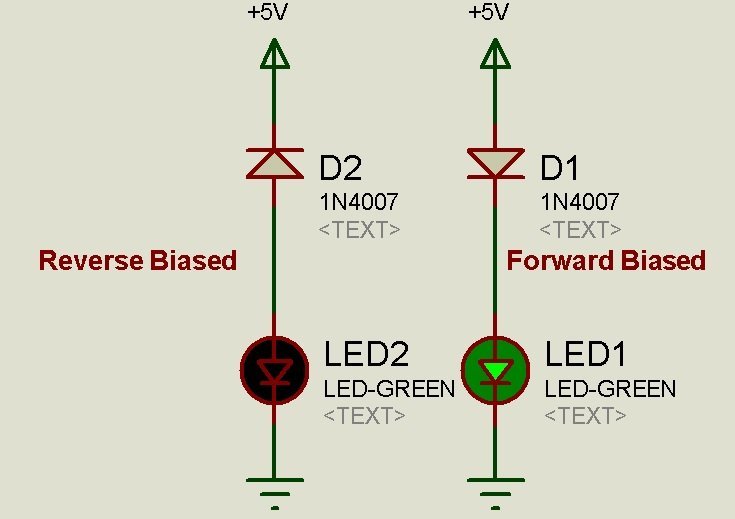
The two circuits represent the states of the diode. The first circuit shows the forward-biased condition of the diode. The anode is connected to the power supply, and the cathode is connected to the ground. In this way, the diode’s anode is at a higher potential than the cathode, due to which the current can surpass its depletion region. The current flows through the LED, and it illuminates.
On the other hand, the second circuit demonstrates the reverse-biased condition in which current can not flow due to depletion region, and the LED does not glow.
1N4007 as a Voltage Regulator
This circuit demonstrates the use of 1N4007 diodes as a voltage regulator. The schematic is a pictorial of a voltage regulator :
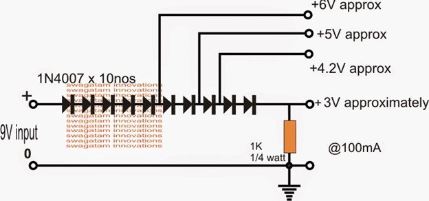
A diode has a depletion region, and when surpassing the barrier, there is a voltage drop of 0.6 Volts. Making use of this potential drop, we can make a voltage regulator per requirement.
To obtain 3 Volts from a 9 Volts power supply, ten 1N4007 diodes are connected back-to-back in a series configuration. When the forward current flows from the first diode through an anode to cathode terminal, 0.6V voltage drops across the first diode and the input voltage for a second diode is 9-0.6 = 8.4v. A similar process happens for each of the diodes and the input voltage gradually decreases from 9 Volts to the required 3 Volts and can be used for the operation of any electronic equipment with a need of ~ 3V.
This is not a recommended design for practical projects but the example circuit is used just to demonstrate the use of 1N4007 diode.
1N4007 Alternative Options
- 1N4148
- 1N5408
- 1N5822
- 1N4733A
- Zener Diodes
Applications
- Rectifiers
- Freewheeling diode applications
- Embedded systems for switching
- Power supplies
- Protection Circuits
Datasheet
The link to the datasheet is given below to see more details and specifications of the 1N4007 diode.
Related Articles:
What about 0.6VDC*7diodesinseries=4.2VDC limiter for Li-ION recharge charger?
as i guess – simple 50Hz*220VAC->5VDC*0.5ADCmax adapter (USB Charger or so) with 7pcs of 1N4007 diodes chain, connected to GND=0VDC & +5VDC output cable of USB smartfone charger-will give not more than 4.2VDC to li-ion rechalgable cell, with current “not thicker than 500mADC” and looks like best simple li-ion charger schematic solution, usually i need LM317(like 7805 stab. but hold(turning OFF=closed when) Voutpin-Vrefpin> +1.2VDC instead of +5V for 1N7805) (such a 1N780…1.2V.) with two resistors shifts Vref pin to +4.2-1.2V(сutoff voltаge)=+3V, f.e. TO-220 LM317 3pins will be like:
[LM317]
| | L(LM317 pow.in pin +5…+20VDC)
| L(LM317 Vrefpin)——————————————————-v
L(LM317 outpin when OK max.=+4.2V)–[1.2K]–(Vref=+3V)–[3.0K]–(0VcommonGND)
ok for li-ion cell recharge if type of your liion cell compatible with 4.2V (100%charged)level