This article is about 3D printers and How 3D printing proceses works. 3D Printing or additive manufacturing is a process of making a three-dimensional solid object of virtually any shape from a digital model. Successive layers of material are laid down to construct a customized object. Each layer can be seen as a thinly sliced horizontal cross-section of the eventual object. The available materials also vary by process. Plastics are the most common, but metals, optically clear and rubber like objects can also be 3D printed. 3D Printing enables the production of complex shapes using less material than traditional subtractive manufacturing methods which involve cutting/ machining out the object from a larger block.
The 3D Printer makes a three-dimensional solid object from a digital model. It consists of 3D printing apparatus attached to a multi-axis robotic arm. The arm consists of a nozzle that deposits metal powder or wire on a surface; and an energy source (laser, electron beam or plasma arc) that melts it, forming a solid object.
Printer Resolution describes layer thickness and X-Y resolution in dots per inch (dpi) or micrometers (μm). Typical layer thickness is around 100 μm (250 dpi). Some machines can print layers as thin as 16 μm (1600 dpi). The particles are around 50 to 100 μm (510 to 250 dpi) in diameter. The X-Y solution is comparable to that of laser printers. Specifying higher resolution results in larger files.
![Figure 1 3D Printed Objects [5]](http://microcontrollerslab.com/wp-content/uploads/2019/10/Figure-1-3D-Printed-Objects-5.png) Figure 1: 3D Printed Objects [5]
Figure 1: 3D Printed Objects [5]
How 3D Printer works?
The first step of 3D printing is 3D scanning. 3D scanning is a process of collecting data on the shape and appearance of a real object, creating a digital model based on it. 3D printable models may be created with a computer-aided design (CAD) package, a 3D scanner or a plain digital camera and photogrammetry software. 3D printed model created with CAD result in reduced errors and can be corrected, allowing verification in the design of the object before it is printed. Most CAD applications produce errors in output STL files of holes, face normals, self-intersections, noise shells etc. Generally, 3D scanning often introduces more errors due to point-by-point acquisition.
The manual modeling process of preparing geometric data for 3D computer graphics is similar to plastic arts such as sculpting. CAD models can be saved in the stereolithography file format (STL), that stores data based on triangulations of the surface of the CAD models. STL is not tailored for additive manufacturing because it generates large file sizes of topology optimized parts and lattice structures; due to the large number of surfaces involved. A newer CAD file format, Additive Manufacturing File Format (AMF) was introduced to store information using curved triangulations.
The STL file is processed by a software called slicer, which converts the model into a series of thin layers and produces a G-code file containing instructions tailored to a specific type of 3D Printer. The G-code file can then be printed with 3D printing client software.
![Figure 2 Working of 3D Printer [4]](http://microcontrollerslab.com/wp-content/uploads/2019/10/Figure-2-Working-of-3D-Printer-4.png) Figure 2: Working of 3D Printer [4]
Figure 2: Working of 3D Printer [4]
3D Printing Process steps
The ISO/ ASTM 52900 standard categorized all different types of 3D printing under one of these seven groups:
- Metal Extrusion (FDM): A spool of filament is loaded into the printer and ten fed to the extrusion head, which is equipped with a heated nozzle. Once the nozzle reaches the desired temperature, a motor drives the filament through to melt it. The printer moves the extrusion head, laying down melted material at precise locations, where it cools and solidifies. When a layer is finished, the build platform moves down and the process repeats until the part is complete. The material becomes ready to use afar removal of support structures or surface smoothing. FDM is the most cost-effective way of producing custom thermoplastic parts and prototypes. It also has the shorted lead times. However, it has the lowest dimensional accuracy and resolution compared to the other 3D printing technologies. FDM parts often require post-processing and surface smoothing. The layer adhesion method makes FDM parts inherently anisotropic and generally weaker in one direction.
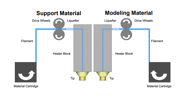 Figure 3: FDM 3D Printing [5]
- Vat Polymerization (SLA and DLP): They are most suitable for visual applications where an injection mold-like smooth surface finish and a high level of feature detail are required. SLA uses a single-point laser to cure the resin, while DLP uses a digital light projector to flash a single image of each layer all at once. Liquid photopolymer in a vat is selectively cured by Ultra-violet light. After printing, the part needs to be cleaned from the resin and exposed to an ultraviolet source to improve its strength. Next, the support structures are removed and post-processing is carried out. SLS pars have a very good, almost isotropic mechanical properties, so they are ideal for functional parts and prototypes. Designs with complex geometries can be easily manufactured. SLS is also excellent for medium batch production. SLS parts have a naturally grainy surface and some internal porosity. The small holes are susceptible to thermal warping and over-sintering.
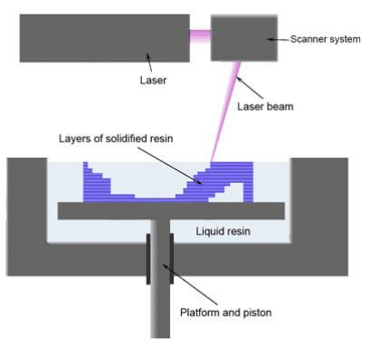 Figure 4: SLA 3D Printing [5]
- Powder Bed Fusion (SLS, DMLS and SLM): DMLS and SLM are suitable for producing metal parts. SLM achieves a full melt of the powder particles, while DMLS heats the metal particles to a point that they fuse together on a molecular level. A high-energy source selectively fuses powder particles. Support structures are always required to minimize the distortion caused by the high temperatures required to fuse the metal particles. After printing the metal supports need to be removed either manually or through CNC machining. Machining may also be employed to improve the accuracy of critical features. Finally, the parts are thermally treated to eliminate any residual stresses. The parts can be optimized to maximize their performance while minimizing their weight. Many metal alloys that are difficult to process with other technologies, such as metal super alloys, are available in DMLS/ SLM. Obviously, the cost of DMLS/ SLM 3D printing are very high. Also, the build size is limited, as precise manufacturing conditions are difficult to maintain for bigger build volumes.
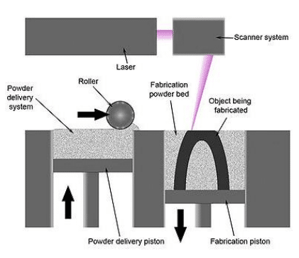 Figure 5: SLS 3D Printing [5]
- Material Jetting (MJ): Droplets of material are selectively deposited or cured. Material jetting works in a similar way to standard inkjet printing. However, instead of printing a single layer, multiple layers of material are deposited upon each other to create a solid part. Multiple print heads jet hundreds of tiny droplets of photopolymer onto the build platform, which are then solidified (cured) by the ultraviolet light source. After a layer is complete, the build platform moves down one layer and the process repeats. Support structures are always required in Material Jetting. A water soluble material is used a s support that can be easily dissolved during post-processing and that is printed at the same time as the structural material. Material jetting is the most precise 3D printing technology. It offers multi-material and full-color printing capabilities. Material jetted parts have a very smooth finish and very high dimensional accuracy. Material jetting is one of the most expensive 3D printing process. Moreover, the printed parts are brittle and photosensitive.
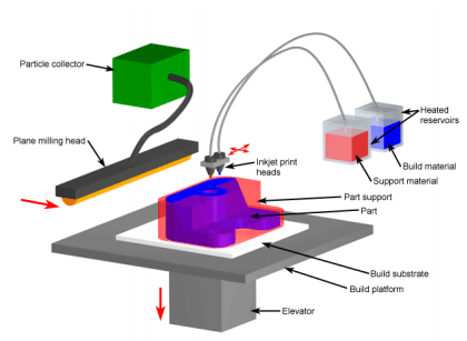 Figure 6: Material Jetting 3D Printer [5]
- Binder Jetting (BJ): Binder Jetting is used for low-cost metal 3D printing, full-color prototyping and large sand casting mold production. A thin layer of powder particles (metal, acrylic or sandstone) is first deposited onto the build platform. The droplets of adhesives are ejected by an inkjet print head to selectively bind the powder particles together and build a part layer-by-layer. After the part is complete, the part is removed from the powder and cleaned. For metal parts, this involves sintering or infiltration with a low melting point metal. Full-color parts are infiltrated with cyanoacrylate adhesive. Binder Jetting can produce metal parts at a fraction of the cost of Material Jetting. Very large parts can also be manufactured with complex geometries. Medium batch production is supported. Metal Binder Jetting parts have lower mechanical properties than the bulk material due to their porosity. Very small details cannot be printed as the parts are very brittle when they leave the printer; and may deform.
- Direct Energy Deposition (LENS, LBMD): A high-energy source fuses material as it is deposited.
- Sheet Lamination (LOM, UAM): Sheets of material are bonded and formed layer-by-layer.
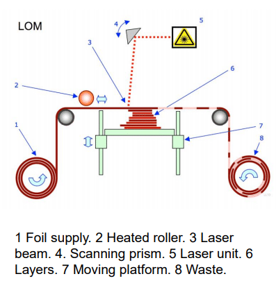 Figure 7: LOM 3D Printing [5]
Applications of 3D Printing
3D Printing encompasses many forms of technologies and materials as 3D printing is being used in almost all industries. A few examples are:
- Construction: 10 one-story houses can be printed in a day.
- Medicine: Hearing aids, Organs, Body parts, Tissues, Blood vessels, Teeth, Prosthetics, Bionics, Braces, eyewear
- Manufacturing: Automobile parts, Cars
- Domestic Usage: Jewelry, Toys, cutlery, Furniture
- Clothing: Dresses, Shoes
- Archaeology: Reconstructing fossils, bones, body parts and ancient artifacts
- Academia: Molecular Models, Gears, Robots.
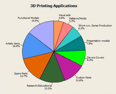 Figure 8: 3D Printing Applications [4]
Tools and Technology used for 3D Printing
Different Software packages can aid in each different stage of the design process; from CAD design, to STL repair and preparation.
Some of the best software for CAD modeling include:
- Solidworks
- Rhinoceros
- Fusion 360
- Onshape
- TinkerCAD
STL repair softwares include:
- Netfabb
- Meshmixer
Some of the popular slicing softwares are:
- Cura
- Simplify3D
 Figure 9: Commercial 3D Printers [1]
References
[1] Wikipedia
[2] 3DPRINTING.COM
[3] 3DHUBS.COM
[4]Researchgate
[5] CS.CMS.EDU