74LS48 is a BCD to seven segments decoder that is used to display numbers decoded in binary coded decimal format. The 7-Segment is a small seven LED-based device use to represent a single numeric value from 0 to 9. Each 7-Segment has seven input pins to light up a single led in the seven segments. Every time to make a single number some specific pins should have power input.
Recommended Components
The following parts are used in this article, along with a generic electronics kit that is handy for building and testing the circuit.
| Component | How it’s used | Buy on Amazon |
|---|---|---|
| 74LS48 BCD-to-7-segment decoder | The 74LS48 BCD-to-7-segment decoder/driver this article covers. | Check Price |
| Electronic component assortment kit (1390 pcs) | A handy assortment of resistors, capacitors, LEDs, diodes and transistors for building circuits. | Check Price |
| Digital multimeter (AstroAI) | Measures voltage, current, resistance and checks continuity while you build and debug. | Check Price |
| Breadboard | Solderless base for prototyping the circuit. | Check Price |
| Jumper Wires | Make the connections on the breadboard. | Check Price |
As an Amazon Associate we earn from qualifying purchases. Prices and availability are accurate as of the date/time indicated and are subject to change.
Introduction to 74LS48 decoder
To do the special pattern we could use logic gates, but an IC 74LS48 can also be used to control the 7-segments. It has 17 AND gate, 4 NOR gate, 6 NOT gates, and 8 NAND gate. These all gates combination makes the IC with 4 input and 7 output pins. The output pins generate two BCD digits in single output, which makes a single number on 7-segment. The IC has 4 input pins which make a total of 16 combinations but the first 10 combinations used to generate the output on 7-segment and the rest of them will be considered as invalid states. The IC is a TTL based device, which allows it to be controlled by any TTL device or microcontroller. It is only used to control common cathode 7-Segments.
Pinout diagram 74LS48
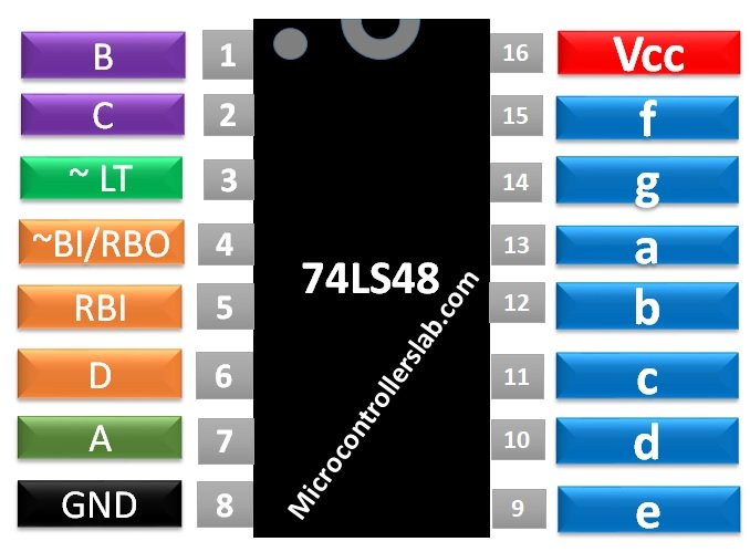
BCD Decoder Pin Configuration
| PINS | DETAIL | |
|---|---|---|
| B | Pin 1 | IC 74LS48 has 4 input pins and Pin 1 represents the third bit of 4-bit input data of the IC. |
| C | Pin 2 | Pin 2 represents the second bit of 4-bit input data of the IC. |
| LT’ | Pin 3 | Pin 3 is known as the lamp test pin. It is used to make all the output pins HIGH to test all the 7-segment led. It’s an active low pin. |
| BI’/BRO’ | Pin 4 | Pin 4 will act as a reset pin. In case of LOW state on pin 4, there won’t be any output. It is an active LOW pin, it will make all the output state LOW. |
| RBI’ | Pin 5 | Pin 5 is known as Ripple Blanking Input pin. It uses in case of multiple 7 segments to clear the unnecessary zeros. |
| D | Pin 6 | Pin 6 represents the MSB of the 4-bit input data of the IC. |
| A | Pin 7 | Pin 7 represents the LSB of the 4-bit input data of the IC. |
| GND | Pin 8 | GND pin is used as a ground pin. It is used to make the ground common to make the IC functional with other TTL devices and microcontrollers. |
| e | Pin 9 | Pin 9 to Pin 15 will be used as the output pins. They will give the output signals to control the 7-segments. The sequence of pins will be a, b, c, d, e, f & g. Every alphabet represents the alphabet of led on 7-segment. |
| d | Pin 10 | |
| c | Pin 11 | |
| b | Pin 12 | |
| a | Pin 13 | |
| g | Pin 14 | |
| f | Pin 15 | |
| VCC | Pin 16 | Pin 16 is used to supply the power to the IC to make it functional. |
FEATURES 74LS48 BCD to 7- Segment Decoder
- It can be used with any TTL device or microcontroller.
- IC 74LS48 comes up with internal clamp diodes, which protects the IC from high-speed termination.
- It has internal pull up resistors which eliminate the requirement of external resistors.
- It comes with Ripple Blanking Input and output pins which helps to remove the unnecessary zero in case of multiple 7-Segments.
- The IC is fully functional with any common cathode 7-segment.
SPECIFICATIONS
- The power supply range for IC is 5.75 to 5.25 Volts and the voltage should not exceed the maximum range.
- The operating temperature range for IC is 0 to 70 degree.
- The output current for the HIGH and LOW state on the output pins a to g is -100uA for HIGH and 6mA for LOW
- The output current range at BI/RBO’ pin is -50uA for HIGH and 3.2mA for LOW.
- The output voltage range is 4.2 for the HIGH state and 0.5 for the LOW state.
For more information on check 74LS48 BCD decoder datasheet
How and Where to use 74LS48?
In IC 74LS48 the output depends on the input. The main input pins are four which helps to generate the fixed output states on specific input data. In a 4-bit binary digit, the decimal zero is represented by 0000 and decimal 9 is represented by 1001, and all the values from 1 to 8 also have fixed 4 digital binary code. Whenever there will be input on the IC from 0 to 9 then the output value will be according to the common cathode 7 segments. It is because the IC was designed to perform that function. In the case of using the IC with 7 segments, we will need to connect the IC with 7-segment according to the given circuit.
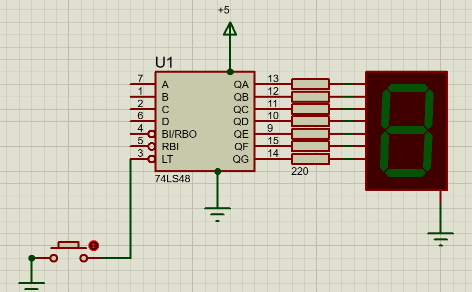
Figure 1: CIRCUIT DIAGRAM
The IC will require 220-ohm resistance to work with the 7-segment. The 7-segment will not need any sperate power supply. It can work with the output of the IC. The multiple 7-segments can be used with multiple IC and RBO can be used to generate the output for the other 74LS48 IC to clear the zero in case of multiple 7-segments. No matter how much IC we use every time the IC will follow the following truth table to show the output.
Truth Table 74LS48
| TRUTH TABLE | |||||||||||
|---|---|---|---|---|---|---|---|---|---|---|---|
| DECIMAL | INPUT | OUTPUT | |||||||||
| D | C | B | A | a | b | c | d | e | F | g | |
| 0 | 0 | 0 | 0 | 0 | 1 | 1 | 1 | 1 | 1 | 1 | 0 |
| 1 | 0 | 0 | 0 | 1 | 0 | 1 | 1 | 0 | 0 | 0 | 0 |
| 2 | 0 | 0 | 1 | 0 | 1 | 1 | 0 | 1 | 1 | 0 | 1 |
| 3 | 0 | 0 | 1 | 1 | 1 | 1 | 1 | 1 | 0 | 0 | 1 |
| 4 | 0 | 1 | 0 | 0 | 0 | 1 | 1 | 0 | 0 | 1 | 1 |
| 5 | 0 | 1 | 0 | 1 | 1 | 0 | 1 | 1 | 0 | 1 | 1 |
| 6 | 0 | 1 | 1 | 0 | 0 | 0 | 1 | 1 | 1 | 1 | 1 |
| 7 | 0 | 1 | 1 | 1 | 1 | 1 | 1 | 0 | 0 | 0 | 0 |
| 8 | 1 | 0 | 0 | 0 | 1 | 1 | 1 | 1 | 1 | 1 | 1 |
| 9 | 1 | 0 | 0 | 1 | 1 | 1 | 1 | 0 | 0 | 1 | 1 |
| 10 | 1 | 0 | 1 | 0 | 0 | 0 | 0 | 1 | 1 | 0 | 1 |
| 11 | 1 | 0 | 1 | 1 | 0 | 0 | 1 | 1 | 0 | 0 | 1 |
| 12 | 1 | 1 | 0 | 0 | 0 | 1 | 0 | 0 | 0 | 1 | 1 |
| 13 | 1 | 1 | 0 | 1 | 1 | 0 | 0 | 1 | 0 | 1 | 1 |
| 14 | 1 | 1 | 1 | 0 | 0 | 0 | 0 | 1 | 1 | 1 | 1 |
| 15 | 1 | 1 | 1 | 1 | 0 | 0 | 0 | 0 | 0 | 0 | 0 |
74LS48 Based Counter Example
In this example, we will design a simple 0 to 9 automatic counters. To give the input data we can use microcontrollers but here we will use 74LS90 IC. Which generates 0-9 four-bit binary data. We will use the IC to give the input to the IC 74LS48. We will give the clock pulse to the IC 74LS90 which will send the data to the IC 74LS48 and the IC 74LS48 will generate the output on 7-segment. Design the Circuit in Proteus and see the result. Although, we have design this counter example with 74LS90, but you can also use 74LS93 4-bit binary counter.
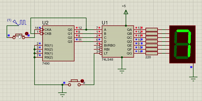
The LT’ pin will turn on all LED and when the clock will be enabled then the circuit will start and start counting until we stop giving the clock pulse. The seven segments don’t have any special initial state but the IC we use here has an initial state which makes the output on led equally to 0. The IC 74LS90 helps here to design the counter but in case of designing other functions, we can use other TTL devices or microcontrollers to handle the IC 74LS49 smartly to design other devices with 7-segment.
Proteus Simulation
APPLICATIONS
- It is used to make a simple counter.
- 7-segment based calculator also used 74LS48.
- It is used in Power Plants with sensors to show the data on digital form.
- It has widely used in industry due to its compatibility with TTL based devices.