In this tutorial, we will discuss the logical instructions of 8086 microprocessor. We will see assembly examples of each logical instruction and output on the simulator. Now let’s discuss all instructions one by one with examples.
AND Instruction
The AND instruction perform logical AND operation between two operands. The source can be an immediate, register, or a memory location and the destination can be either a register or a memory location. Both source and destination operands cannot be a memory location. It ANDs each bit of source operand with the destination operand and stores the result back into the destination operand. However, the content of the source operand remains unchanged. If both input bits are 1, only then AND operation will generate 1 as an output bit.
Format : AND Destination, Source
AND Logic Example
Suppose two numbers 3527 and 2968.
Binary of 3527: 1101 1100 0111
Binary of 2968: 1011 1001 1000
The AND operation between these two numbers give:

The hexadecimal value of 1001 1000 0000
is 980.
AND Assembly Example
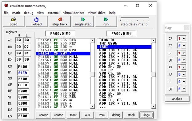
The code is given below. The two numbers are stored in BX and CX. The final result obtained after AND operation goes to the BX register.
ORG 100h
.MODEL SMALL
.CODE
MOV BX,3527
MOV CX,2968
AND BX,CX
RET
Output:

8086 OR Logical Instruction
It performs the OR operation between two operands and stores the result back into the destination operand. The destination operand can be a register or a memory location whereas the source can be immediate, register, or a memory location. But Keep in mind, both operands should not be a memory location. The OR instruction clears the CF and OF flags to 0 and update PF, ZF, and SF flags. The OR operation gives 1 at output if any one input is 1 and give 0 on output only when both inputs are 0.
Format : OR Destination, Source
OR Logic Example
Suppose two numbers 3527 and 2968. The OR operation between these two numbers give:
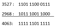
The hexadecimal value of 4063 is FDF.
OR Assembly Example
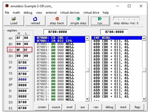
The code given performs the OR operation between contents of CX register and the data stored at offset address 102h.
ORG 100h
.MODEL SMALL
.DATA
VAR_1 DW 3527
.CODE
MOV AX, 0700h
MOV DS, AX
MOV CX, 2968
OR CX, [102h]
RET
Output:
XOR Instruction 8086
This instruction performs the XOR operation between bits of source and destination operands. The XOR operation gives 1 when both inputs are different. When both inputs are same then the output will be zero. The source operand can be either a register or memory address whereas destination operand can be immediate, register or memory location.
Format: XOR Destination, Source
XOR Logic Example
Suppose AH is loaded with 68H. The XOR instruction performs the XOR operation between the contents of AH and the immediate value of 9CH.

Assembly Example
ORG 100h
.MODEL SMALL
.CODE
MOV AH,68H
XOR AH,9CH
RET
Output:
The red box in the output indicates the result produced by XOR operation.
NEG 2’s Complement Instruction
The NEG instruction compute the 2’s complement of the destination operand. The destination can be a register or memory address. It can change AF, PF, ZF and OF flags of flag register.
Format: NEG Destination
Assembly Example![]()
ORG 100h
.MODEL SMALL
.CODE
MOV AX, 25H ;Sets AX to 25H
NEG AX ;Compute 2's complement of data in AX
MOV DX,0711H
MOV DS,DX ;Sets Data Stack pointer to 0711H
NEG [9H] ;Compute 2's complement of value stored at memory address DS:0009H
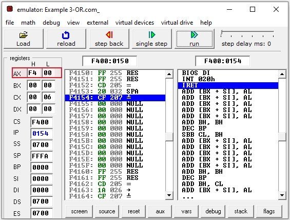
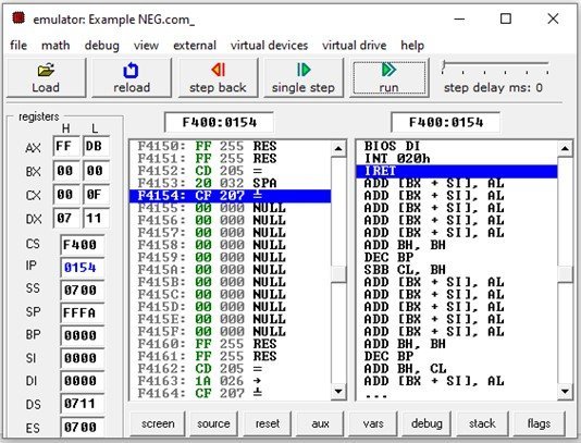
RET ;Stops the programOutput:
The NEG AX instruction computes the 2‘s complement of AX data and store it in AX register. The two’s complement of 25H can be found out by converting it to a binary number. The binary of 25H is 0000 0000 0010 0101. Invert all the bits and add 1 to the result. The two’s complement would be:

The haexadecimal value of 1111 1111 1101 1011 is FFDB. Thus AX becomes equal to FFDB. In the last instruction NEG [9H] , the two’s complement of data stored at offset address 0009H is computed.
CMP Compare Instruction 8086
The compare instruction (CMP) compares the data of the two operands and depending upon the result sets the flag.The destination operand remains unchanged. It compares the two operands by computing the difference of two operands and sets CF, ZF and SF flags.
Format: CMP Destination, Source
| CF | ZF | SF | |
| Dest=Source | 0 | 1 | 0 |
| Dest>Source | 0 | 0 | 0 |
| Dest<Source | 1 | 0 | 1 |
The source and destination can be a register, immediate number, or a memory address. But, both operands cannot be a memory address in the same instruction. The CMP cannot directly compare the data of two memory addresses.
CMP Assembly Example
ORG 100h
.MODEL SMALL
.CODE
MOV AX, 0025H  ;Sets AX to 25H
MOV BX, 00A5H  ;Sets BX to A5H
CMP AX, BX     ;Compare the contents of AX to BX
RET            ;Stops the program
Output:
It checks the contents of AX and BX. In this example, BX is greater than AX. The difference AX-BX sets CF and SF to 1 whereas the content of AX remains unaffected.
Output:

Shift Right Instruction
There are two shift right instructions namely logical shift right (SHR) and Arithmetic shift right (SAR). Both instructions are explained below.
Format: SHR Destination, Count
SHR is a logical shift right instruction used for unsigned operands. It shifts the bits of operand one by one to the right. In every shift, the least significant bit goes to the carry flag and insert zeros in the higher bit. The operand to be shifted can be a register or a memory location. Specify the number of shifts by loading the value into CL register. If the bits are to be shifted once, then specify it in the instruction. The destination operand can be a register, or a memory location and count indicate the number of shifts.
Right Shift Instruction Assembly Example 1
Suppose BL register contains hexadecimal value of 6D. The binary value of 6D is 0110 1101.
SHR BL, 1 instruction will shift 6D by 1. So the least significant bit which is 1 goes to carry flag and all others bits are shifted by 1. Insert 0 at the most significant bit. So, the final result obtained after shifting is (0011 0110) whose hexadecimal value is 36.
ORG 100h
.MODEL SMALL
.CODE
MOV BL,6DH
SHR BL,1
RET
Output:

Assembly Example 2
Suppose if you want to shift it 3 times. Then, you’ll first load CL register with 3.
Operand to be shifted is 0110 1101.
1st shift: 0011 0110 CF=1
2nd shift: 0001 1011 CF=0
3rd shift: 0000 1101 CF=1
Hence the final result is 0000 1101 whose hexadecimal value is D.
ORG 100h
.MODEL SMALL
.CODE
MOV CL, 3
MOV BL,6DH
SHR BL,CL
RET
Output:

8086 Arithemtic Right Shift Instruction
This instruction is arithmetic right shift which deals with signed operands. The operation of this instruction is similar to the SHR instruction. The only difference is when the bits are shifted to the right, the empty bits at MSB are filled with sign bit instead of zeros. This instruction can also be used for division of signed number by 2 if the count is 1.
Format: SAR Destination, Count
SAR Assembly Example
ORG 100h
.MODEL SMALL
.CODE
MOV CL, 1
MOV BL,-6DH
SAR BL,CL
RET
Output:
Shift Left Instruction
There are two shift left instructions. One is used for signed operands and the other one is used for unsigned operands. Both instructions are explained in this section.
Format: SHL Destination, Count
The SHL is the logical left shift for unsigned operands. It shifts the operand bits to the left. The destination can be a register or a memory location. The number of shifts are stored in CL register which is then loaded in the count operand. If the number of shifts are 1, then you can directly specify it in the instructions like SHL Destination, 1. After shifting, the MSB goes to CF flag register and LSB is filled with zeros.
Left Shift Assembly Example
Suppose AX is equal to 029AH and count is 2. Then
Binary value of Operand 029A = 0010 1001 1010
1st shift: 0101 0011 0100 CF=0
2nd shift: 1010 0110 1000 CF=1
The hexadecimal value of 1010 0110 1000 is A68H.
ORG 100h
.MODEL SMALL
.CODE
MOV CL, 2
MOV AX,029AH
SHL AX,CL
RET
Output:

SAL Instruction 8086
The SAL has similar operation to the SHL instruction. The most significant bit of operand remains unchanged as it is a signed bit while remaining bits are shifted to the left and the empty bits at LSB are filled with zeros.
Format: SAL Destination, Count
SAL Assembly Example
ORG 100h
.MODEL SMALL
.CODE
MOV CL, 2
MOV AX,-029AH
SAL AX,CL
RET
Output:

Other 8086 Tutorials:
Write an assembly language program of 8086 to perform xor,nor and nand on 16-bit numbers
Output: BX=09 80 ???
-A 100
0100 MOV BX,3527
0103 MOV CX,2968
0106 AND BX,CX
0108
-R
AX=0000 BX=0000 CX=0000 DX=0000
0100 BB2735 MOV BX,3527
-T
AX=0000 BX=3527 CX=0000 DX=0000
0103 B96829 MOV CX,2968
-T
AX=0000 BX=3527 CX=2968 DX=0000
0106 21CB AND BX,CX
-T
AX=0000 BX=2120