This article contains information on 8086 microprocessor adressing mode and each addressing mode is explained with examples.
What is Adressing Mode?
Addressing modes are different ways by which CPU can access data or operands. They determine how to access a specific memory address. To load any data from and to memory/registers, MOV instruction is used. The syntax of MOV instruction is:
MOV Destination, SourceIt copies the data of 2nd operand (source) into the 1st operand (destination). To access memory, segment registers are used along with general-purpose registers.
If you don’t know about internal register of 8086 microprocessor, read this article:
8086 Microprocessor Architecture
There are seven addressing modes in 8086 processor. Now, we will discuss all of them in detail with example assembly instructions.
1. Register addressing mode
This mode involves the use of registers. These registers hold the operands. This mode is very fast as compared to others because CPU doesn’t need to access memory. CPU can directly perform an operation through registers.
For example:
MOV AX, BL
MOV AL, BL
The above two instructions copy the data of BL register to AX and AL.
Example Assembly Code
The ORG 100h is a directive which tells the compiler how to handle the source code.
ORG 100h
MOV AX,CX
ret
Output:
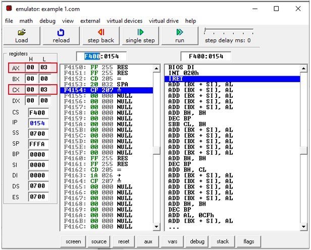
In this example, you can see a red box in the output. This red box indicates the content of AX and CX registers. The content of both AX and CX registers are the same. Because the above example moves the content of CX into AX register.
2. Immediate Addressing Mode
In this mode, there are two operands. One is a register and the other is a constant value. The register comes quickly after the op code.
For example:
- The instruction MOV AX, 30H copies hexadecimal value 30H to register AX.
- The instructions MOV BX, 255 copies decimal value 255 to register BX.
You cannot use the immediate addressing mode to load immediate value into segment registers. To move any value into segment registers, first load that value into a general-purpose register then add this value into segment register.
Example Assembly Code
Let us suppose you want to store 320H into DS register.
ORG 100h
MOV AX,320H    ;copies hexadecimal value 320h to AX
MOV DS, AX     ;copies value of AX into DS
ret            ;stops the program
Output
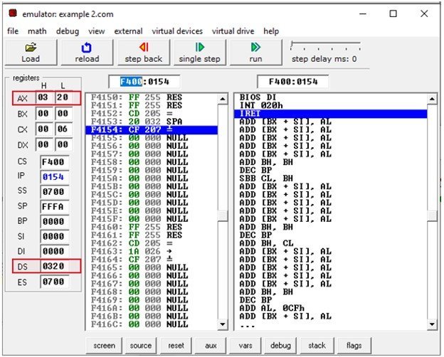
If 0320h is added directly into the DS register using MOV instruction, the compiler will generate an error.
3. Direct Addressing Mode
It loads or stores the data from memory to register and vice versa. The instruction consists of a register and an offset address. To compute physical address, shift left the DS register and add the offset address into it.
MOV CX, [481]The hexadecimal value of 481 is 1E1. Assume DS=2162H then the logical address will be 2162:01E1. To compute physical address, shift left the DS register and add it to offset address. The physical address will be 26120H + 1E1H=26301H. Hence, after execution of the MOV instruction the contents of the memory location 26301H will be loaded into the register CX. The instruction MOV [2481], CX will store the CX register content to memory location 26301H.
Example Code
ORG 100h
MOV AX, 2162H   ;copies hexadecimal value 2162h to AX
MOV DS, AX      ;copies value of AX into DS
MOV CX, 24      ;copies decimal value 24 into CX
MOV [481], CX  ;stores the data of CX to memory address 2162:01E1
MOV BX, [481]  ;load data from memory address 2162:01E1 into BX
RET             ;stops the program
Output

In this example, the red box indicates the hexadecimal value 18 and decimal value 24 is stored at memory address 21801h.
4. Register Indirect Addressing Mode
The register indirect addressing mode uses the offset address which resides in one of these three registers i.e., BX, SI, DI. The sum of offset address and the DS value shifted by one position generates a physical address. For example:
MOV AL, [SI]
This instruction will calculate the physical address by shifting DS to the left by one position and adding it to the offset address residing in SI. The brackets around SI indicates that the SI contain the offset address of memory location whose data needs to be accessed. If brackets are absent, then the instruction will copy the contents of SI register to AL. Therefore, brackets are necessary.
Example Code
ORG 100h
MOV AX, 0708h   ;set AX to hexadecimal value of 0708h.
MOV DS, AX      ;copy value of AX to DS
MOV CX, 0154h   ;set CX to hexadecimal value of 0154h.
MOV SI, 42Ah    ;set SI to 42Ah.
MOV [SI], CX    ;copy contents of CX to memory at 0708:042Ah
RET             ;returns to operating system
Output

In the above example, the physical address is 07080 + 042A = 74AA. According to the little-endian convention, the 074AA will store the lowest bytes of data i.e., 54 and the 074AB will store the most significant bits of data i.e. 01.
5. Based Relative Addressing Mode
This addressing mode uses a base register either BX or BP and a displacement value to calculate physical address.
Physical Address= Segment Register (Shifted to left by 1) + Effective address
The effective address is the sum of offset register and displacement value. The default segments for BX and BP are DS and SS. For example:
MOV [BX+5], DXIn this example, the effective address is BX + 5 and the physical address is DS (shifted left) + BX+5. The instruction on execution will copy the value of DX to memory location of physical address= DS (shifted left) +BX+5.
Example 1 Code
ORG 100h
MOV AX, 0708h   ;set AX to hexadecimal value of 0708h.
MOV DS, AX      ;copy value of AX to DS
MOV CX, 0154h   ;set CX to hexadecimal value of 0154h.
MOV BX, 42Ah    ;set BX to 42Ah.
MOV [BX+5],DX   ;copy contents of DX to memory at 0708:042Fh
RET             ;returns to operating system
Output

Some other alternative codings for MOV DX, [BX+5] are:
MOV DX, 5[BX]
MOV DX, [BX]+5
The instructions given below will load the value from memory location to register.
MOV [BX+10], DX
Now, suppose the base register is BP. Then, in this case, the default segment would be SS. In the above example, replace BX by BP. Now the physical address is equal to SS (shifted left) +BX+5 which is equal to 742F.
Example 2 Code
ORG 100h
MOV AX, 0708h   ;set AX to hexadecimal value of 0708h.
MOV DS, AX      ;copy value of AX to DS
MOV DX, 0154h   ;set DX to hexadecimal value of 0154h.
MOV BP, 42Ah    ;set BP to 42Ah.
MOV [BP+5],DX   ;copy contents of DX to memory at 0708:042Fh
RET             ;returns to operating system
Output

6. Indexed Relative Addressing Mode
This addressing mode is same as the based relative addressing mode. The only difference is it uses DI and SI registers instead of BX and BP registers.
For example:
Given that DS=704, SI = 2B2, DI= 145
MOV [DI]+12, ALThis instruction on execution will copy the content of AL at memory address 7197 (7040 + 145 + 12)
MOV BX, [SI]+10This instruction will load the contents from memory address 7302 (7040 +2B2 +10) to register BX.
7. Based Indexed Addressing Mode
The based indexed addressing mode is actually a combination of based relative addressing mode and indexed relative addressing mode. It uses one base register (BX, BP) and one index register (SI, DI). For example:
MOV AX, [BX+SI+20]The above instruction can also be written as:
MOV AX, [SI+BX+20]Or
MOV AX, [SI][BX]+20In this case, the physical address will be DS (Shifted left) + SI + BX + 20. Now, if we replace BX with BP then the physical address is equal to SS (Shifted left) + SI + BX + 20.
Now, let us have a look on these two instructions:
MOV AX, [BX][BP]+20
MOV AX, [SI][DI]+20
Both expressions are illegal as this mode supports one base register and one segment register.
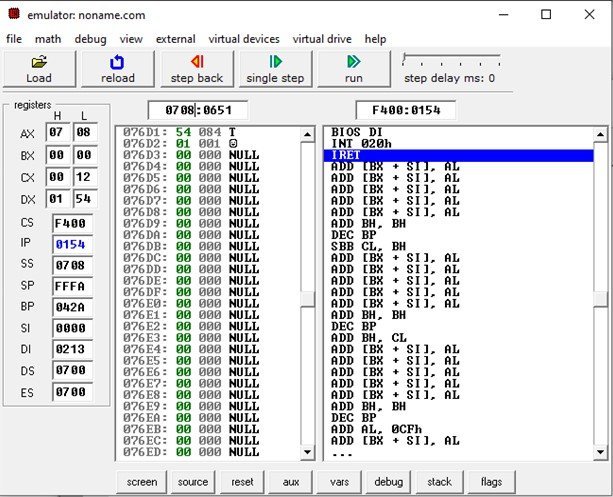
Example Code
ORG 100h
MOV AX, 0708h      ;set AX to hexadecimal value of 0708h.
MOV SS, AX         ;copy data of AX to DS
MOV DX, 0154h      ;store hexadecimal value of 0154h in DX.
MOV BP, 42Ah       ;store hexadecimal value of 42Ah in BP.
MOV DI, 213h       ;store hexadecimal value of 213h inDI
MOV [BP+DI+20],DX  ;copy contents of DX to memory address 0708:0651
RET                ;stops the program
Output
In conclusion, addressing modes are ways to access the operands. The programmer can use any of these seven addressing modes depending upon the program.
It’s a nice article with full information. Thank you for letting me read it.
Thank you for this useful info.
It’s missing Implied Addressing Mode
Write an set of instruction to demonstrate the various type of Addressing modes and
display the register contents for every instructions.
Answer please
I think your description of mov CX, [481] in “3. Direct Addressing Mode” is incorrect.
It appears you may have flipped a 16 and 61 in the values for calculating effective address:
“The hexadecimal value of 481 is 1E1. Assume DS=2162H then the logical address will be 2162:01E1. To compute physical address, shift left the DS register and add it to offset address. The physical address will be 26120H + 1E1H=26301H. Hence, after execution of the MOV instruction the contents of the memory location 26301H will be loaded into the register CX. The instruction MOV [2481], CX will store the CX register content to memory location 26301H.”
I believe the effective address is: 21620h + 1E1h = 21801h
Which does match what the emulator shows in executing the similar code example.
quite insightful. Thank you