MOC3041 is an optocoupler but unlike other optoisolators, it has a special feature of zero-crossing based switching. It is based on zero-crossing. MOC304X series also used to operate the external TRIACS, SSR, and MOSFETS. MOC3041 is mostly used to control AC load switching by automatically detecting the zero cross but it has internal TRIAC which can hold up to 1A current and IR communication keep the controlling device of optocoupler safe. The zero-crossing detector will be able to detect the zero volts from the AC and will turn on and off the TRIAC of the IC that will be able to protect the external load from damaging itself and switching surges of other circuits.
MOC3041 Introduction
MOC304X Series of optoisolators contains MOC3041, MOC3042 and MOC3043. All these integrated circuits have the same pinout diagram, electrical features, and applications except IFT current that is input side LED trigger current. The table shows the IFT current for these optoisolators. Therefore, We will consider examples for MOC3041 only and you can apply the same concept to others also.

M0C3041 Pin Configuration
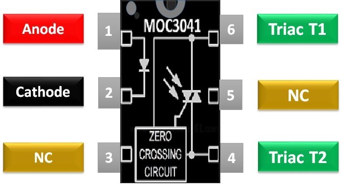
This is a pinout diagram of the MOC3041 series. For details of each pin consult of the table give after pinout diagram.
| INPUTS PINS | ||
|---|---|---|
| Anode | Pin 1 | Pin 1 is an anode pin of the IR transmitter used to give the logical/power input to generate an IR signal. |
| Cathode | Pin 2 | Pin 2 is a cathode pin of the IR Transmitter used to make the common ground with the IC input controlling circuit. |
| NC | Pin 3 | Pin 3 is a no connection pin, which has no internal connection. It will have no effect on the IC if it gets connected with the circuit |
| OUTPUT PINS | ||
| TRIAC T2 | Pin 4 | Pin 4 is connected to the internal TRIAC of the IC, which is used to control the external TRIAC, etc. |
| NC | Pin 5 | Pin 5 is also a no connection pin. |
| TRIAC T1 | Pin 6 | Pin 6 is the second control pin of the TRIAC of the IC. |
EQUIVALENT Options
MOC3031M, MOC3032, MOC3033M, MOC3041M, MOC3042M and MOC3043M.
ALTERNATIVE Options
6N137 (High Speed), MOC3021 (non-zero cross) , 6N135, PC817.
Where to use MOC3041?
The structure of MOC304X optocoupler is based on simple IR communication, its transmitter part is based on an LED which is only used to transmit the IR signal on logical input. The other part is a known monolithic silicon detector, which is used to perform the zero-cross voltage and TRIAC function. MOC3041 is used with high load AC switching, which is the reason TRIAC is used to hold the Power.
The zero-cross is mostly used in digital dimmer to generate timing signals but here it will be used only to find the zero voltage at each cycle of AC. The AC load always turn on and off within a specific period of time. During this period of time the device could heat up and there’s a chance that the device could get burned. For the safety of the load, a zero-cross method is used, which detects the zero volts from the AC sign wave. Whenever the voltage reaches 0V in each cycle the internal TRIAC becomes active, during this period the TRIAC of optocoupler can be used for switching. By this method, the load will have a rare chance to subjected to the maximum voltages.
How MOC3042 Optoisolator works
MOC3041 can bear up to 400VAC but it should not be subjected directly to the external load due to its safety. Whenever optocoupler needs to be used some protocols need to be followed, all these protocols will be followed by the output end.

The output will be controlled through external TRIACS and 39ohm resistor and 0.01uF polarized capacitor, capacitor and resistor in series will be attached parallel to the TRIAC for snubbing but it’s an option which can be removed by using the snubber-less TRIACS. The value of capacitor and resistance could vary with different TRIACS and load but this value is mostly used with 240VAC. To use the TRIAC with MOC3041, resistance will be used to minimize the voltages.
The input will be delivered by output pins of the microcontrollers. The Anode pin will be connected to the power supply and the cathode pin will be connected to a NAND gate which will be able to control the MOC3041 using PWM. One pin of the NAND gate will be grounded but the other will be used to control the IC through PWM by using microcontrollers. Due to the NAND gate, the IC will be active only when inputs will be LOW. The use of PWM from the controller allows the optocoupler to variate power on load.
MOC3041 Example Interfacing 220 Lamp
In this Example of MOC3041, we will use the optocoupler with TRIAC and will see how it works with it. First, draw a general operating circuit of optocoupler in proteus. In-circuit diagram as we discuss snubbing circuit with the optocoupler, in proteus, you will view some snubber less TRIAC which can be used with the circuit to make the circuit simpler. After drawing the circuit control, it with a simple button. Then control the circuit and you will view the LAMP light up as shown in the given image.

The lamp will turn on and off without any delay, which can be understood by the nature of the current. Just add an oscilloscope at the end of the load and visualize the wave nature. To understand it carefully we increase the frequency too.

Figure 1:Turned OFF

Figure 2:Turned On
As you can see in the image as the button is pressed the current start flowing the load from zero. when the optocoupler turns off then the wave doesn’t suddenly stop. It stops at zero because the zero-cross detector in the circuit doesn’t allow it to stop before the 0V which keeps the load from any kind of loss.
More Examples
In MOSFETs and relay module, the optocoupler is connected to control the load but after the invention of IoT, the optocoupler is not only used as a switch it used with smart controller to perform automatic functions like: In case of an increase in room temperature the temperature sensor will detect the room temperature and will variate the speed of the cooler fan to keep the temperature normal. This goes the same with the decrease in temperature to control the heater. Due to the new era of IoT, the MOC3041 and its alternatives are being used vastly to control the HIGH LOAD by using smart controllers. You can check these guides also:
Proteus Simulation
APPLICATIONS
- MOC3041 is used in Home Automaton to control the light intensity.
- AC/DC power can be control by the IC, which lead it to control the motors speed.
- In noise coupling circuit IC is used to remove the noise.
- EM contractors, Solid State Relays and MOSFETS use the optocoupler to operate for the protection of the operating device.
- Electronics valve is being controlled by using the MOC3041.
MOC3041 FEATURES
- IC MOC3041 has an internal zero-cross detector to protect the load.
- The internal TRIAC of the IC can handle the voltage of 110 to 400VAC and 1A current too.
- It comes with and without M-Suffix in 6-pin PDIP.
- Due to logical input, the IC can be operated using any microcontroller and TTL based device.
- PWM input can be used as input in optocoupler to variate the output.
- The IC allows the external devices to receive the full load because of zero crosses.
SPECIFICATIONS
- To trigger the IR transmitter minimum of 1.3 Volts and a maximum of 15mA current are required.
- The operating temperature range for IC is -40 to 85 degree but it can store temperature up to +150 degree.
- The total power dissipation at 25 degrees is 250mW but it could vary with the temperature.
- The isolation surge voltage for optocoupler is up to 7500VAC for 60Hz.
- The emitter has a reverse leakage voltage of about 6V.
- The internal TRIAC can hold up to continuous 400V and 1A.
2D MODEL MOC3041

Very helpful!!!
Nice work.
But I am not agree with this: ‘It stops at zero because the zero-cross detector in the circuit doesn’t allow it to stop before the 0V’. This is not true. Once lached, tyristor conduct till zero volts, this is basical caracteristic of tyristor. It doesn’t need any circuit to do this.
Your understanding of thyristor family is correct. However, this zero-crossing feature in this unit, simply detects 0V from the AC line, then “enables” the gate for the TRIAC.
So, for instance, when a MCU output goes active HIGH, the load voltage could be in the 1/4 of a cycle at 85Volts peak. This would surge high voltage to the load and not be consistence based on when the MCU goes HIGH. This circuit waits until the load voltage goes back to 0V, then turns ON the TRIAC so it can begin to conduct. The load voltage will always begin at 0V potential then progress to its final level… whether its Negative or Positive.
I have a question about this circuit. HOw much power is being dissipated by the 39 ohm resistor when the triac is off? Let’s say there’s a 2Kw load on the triac so the load has a resistance of 240^2/2000 = 29 ohms which adds to the 39 ohms to give a total of 68 ohms of pure resistance. The capacitive reactance of the capacitor =1/2*pi*f*C =318 ohms. I think the total reactance is calculated like a right angle triangle = sqrt(318^2 + 68^2) = 325 ohms. That means even when the triac is switched off theres a current of 240/325=0.73 Amps flowing. This cant be right? What have I done wrong in this calculation?
HI Patrick!
Your mistake is in the capacitive reactance The correct answer is 318 kohms!
Hello!
How can we detect the zero cross line with this optocoupler. How could me send this information to arduino?
How can one get a 10 nano farad (0.01 micro farad) electrolytic capacitor? There isn’t such a thing in the consumer market. You can get polyester or ceramic capacitors for this value of capacitance.