In the world of IoT (Internet of Things), wireless communication between devices is a crucial aspect. ESP-NOW is a low-power, secure, and direct wireless communication protocol that allows multiple ESP32 devices to communicate with each other without the need for Wi-Fi or a router. In this tutorial, we will learn how to perform wireless communication between two ESP32 boards by using the ESP-NOW protocol developed by Expressif. We will transmit sensor readings between two ESP32 boards and display the readings on an OLED display. Each board will be connected with a DHT22 sensor and an OLED display.
Any appropriate sensor can be used such as DS18B20, BME680, LM35, and MPU6050 but for this project, we will use a DHT22 sensor which is used to measure temperature and humidity.
This article is divided into these sub-topics:
- ESP-NOW Protocol Introduction
- Project Overview
- Introduction to DHT22 sensor and connecting it with the ESP32 board and the OLED display
- Setting up Arduino IDE for ESP-NOW communication between two ESP32 boards to transmit sensor data (installing libraries, Arduino sketch and demonstration)
Recommended Components
The following components are used in this project or are helpful for building it with the ESP32.
| Component | How it’s used in this project | Buy on Amazon |
|---|---|---|
| ESP32 Development Board | Two of these boards exchange data over ESP-NOW in this two-way demo. | Check Price |
| Micro USB Cable | Powers each ESP32 and uploads the sender and receiver sketches. | Check Price |
| Breadboard | Holds the boards and any peripherals for solderless prototyping. | Check Price |
| Jumper Wires | Connect power and any attached components to the ESP32 pins. | Check Price |
As an Amazon Associate we earn from qualifying purchases. Prices and availability are accurate as of the date/time indicated and are subject to change.
ESP-NOW Protocol Introduction
Using ESP-NOW, we can perform one-way and even two-way communication between ESP MCU devices without using a Wi-Fi network. It allows low-overhead peer-to-peer wireless data transfers but in small packets. A maximum of 250 bytes of data can be transferred. Thus if a larger amount of data needs to be transferred then using this protocol is not useful. Using ESP-NOW, the connection protocol is simplified which results in low power consumption as a lesser amount of time is required for the transmission of data. Additionally, the ESP-NOW uses the same 2.4 GHz band as the Wi-Fi but does not need to connect or interfere with the local network connection. It is a fast and convenient communication protocol for the transmission of a smaller amount of data.
Recommended Reading: ESP32 ESP-NOW Getting Started Tutorial with Arduino IDE
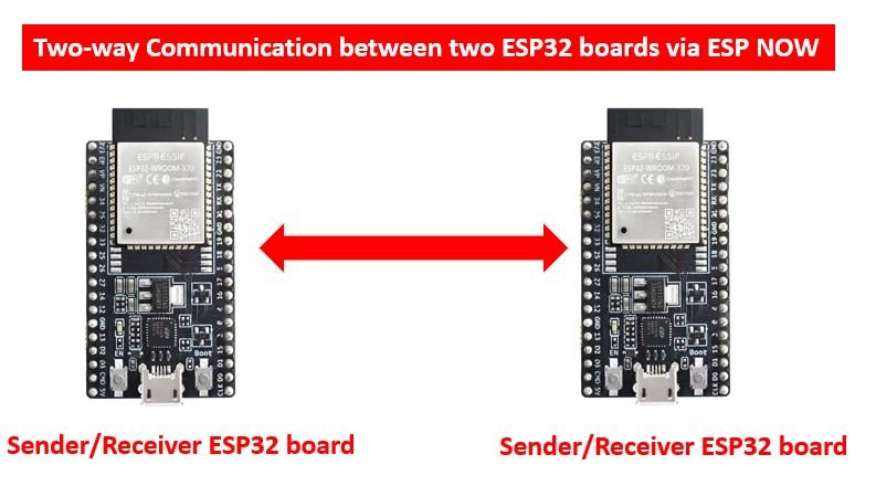
ESP-NOW Two-Way communication
Apart from one-way communication, the ESP-NOW protocol also enables two-way communication between peered devices. In this case, the ESP32 board can act as both the sender (master) and the receiver (slave) simultaneously. We can have two ESP32 boards transmitting data as shown below:
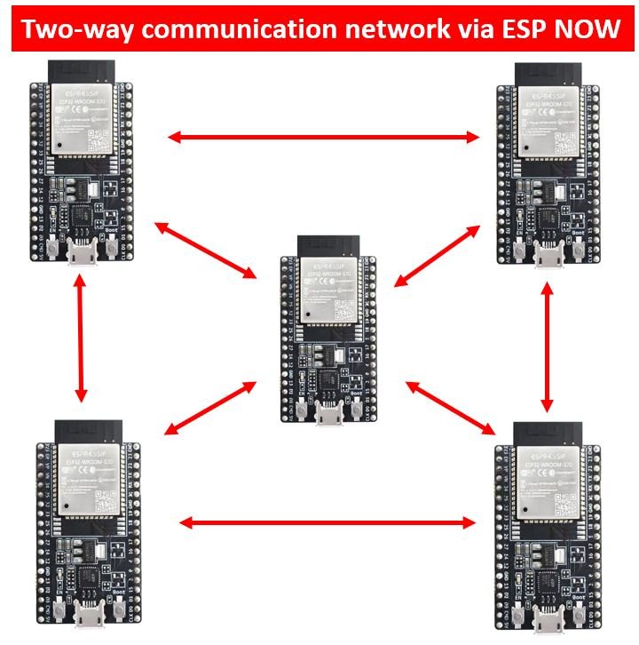
Or even have a network of ESP32 boards transmitting data:
ESP-NOW Two way Communication Project Overview
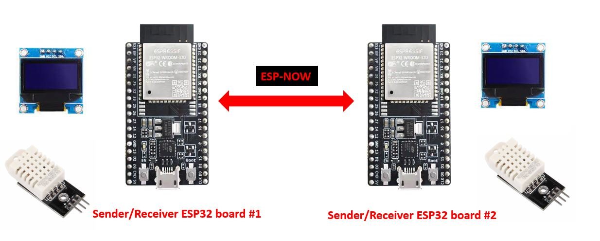
This project consists of two sets of ESP32 boards connected with a DHT22 sensor and an OLED display. First, we will find the MAC address of each board through an Arduino sketch to differentiate between the two modules. Then after programming the two boards, each board will receive sensor data that includes temperature and humidity values from the other board through ESP-NOW protocol. These values will be displayed in their respective OLED displays. Basically, ESP32 #1 sends its sensor readings to ESP32 #2 and ESP32 #2 sends its sensor readings to ESP32 #1. Thus, the OLED screen will display the sensor readings obtained from the other board.
Required Components:
- 2x ESP32 development boards
- 2x DHT22 sensors
- Connecting wires
- 2x 10k pull up resistors (if using DHT22 sensor module then not required)
- 2x SSD1206 0.96 inch OLED displays
- Breadboard
DHT22 sensor Introduction
The DHT22 is an inexpensive sensor that measures relative humidity and temperature. It provides a calibrated digital output with a 1-wire protocol. It measures temperature and humidity with higher accuracy and supports a wider range compared to the DHT11.
DHT sensors are pre-calibrated. We can directly connect them to ESP32 boards to obtain sensor output readings. They internally consist of a humidity sensing sensor and a thermistor. These two components measure humidity and temperature.
DHT22 Pinout
The following figure shows the pinout diagram of DHT sensors. DHT sensor consists of four pins. But on DHT modules only three pins are exposed to the pinout of the module and the 10k ohm pull-up resistor is internally connected to pin 2.
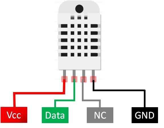
The following lists the pinout of the DHT sensor and their brief description. Pin number starts from left to right when you hold the sensor from the front end. It also shows how these pins will be connected with the ESP32 board.
| DHT22 Pins | ESP32 |
|---|---|
| 1 (VCC) | 3.3V |
| 2 (Data) | Any GPIO pins of ESP32 board along with 10k ohm pull-up resistor |
| 3 (NC) | Not used |
| 4 (GND) | Ground |
- VCC is the power supply pin. Apply voltage in a range of 3.3 V to 5.0 V to this pin
- Data Out is the digital output pin. It sends out the value of measured temperature and humidity in the form of serial data
- N/C is not connected
- GND: Connect the GND pin
ESP32 Interfacing with DHT22 and OLED Display
In this section, we will see how to connect OLED and DHT22 with ESP32.
ESP32 with OLED Display
Let us take a look at the OLED display which we will be using in this article. It is called SSD 1306 0.96-inch OLED display which has 128×64 pixels and communicates only via I2C protocol with the ESP development boards. It is cheap and readily available in the market.
You can read this in-depth guide:
OLED Display Interfacing with ESP32 – Display Text, Draw Shapes and Images
Below you can see the pinout of this OLED Display.
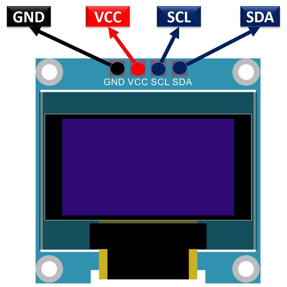
SSD1306 OLED Pinout
There are four pins in this display. Imprinted as VCC, GND, SCL, and SDA respectively. The VCC and GND pins will power the OLED display and will be connected with the ESP board’s power supply pins as they require a driving voltage of 3.3-5V. The SCL and SDA pins are necessary for generating the clock signal and in the transmission of data respectively. Both of these pins will be connected with the I2C pins of the ESP32 board.
Connecting SSD1306 OLED Display with ESP32
As we have seen above, the OLED display has 4 terminals which we will connect with the ESP32 board. As the OLED display requires an operating voltage in the range of 3.3-5V hence we will connect the VCC terminal with 3.3V which will be in common with the ESP32 board. SCL of the display will be connected with the SCL pin of the module and the SDA of the display will be connected with the SDA of the module. By default, the I2C pin in ESP32 for SDA is GPIO21, and for SCL is GPIO22. The connections between the two devices can be seen below.
| ESP32 board | SSD1306 OLED Display |
| VCC=3.3V | VCC |
| GPIO21(I2C SDA) | SDA |
| GPIO22(I2C SCL) | SCL |
| GND | GND |
The I2C pins stated above are set in default. If you want to use any GPIO pins for I2C, you will have to set it in code using SoftI2C().
ESP32 Connection Diagram with DHT22 and OLED
This section shows how to connect the ESP32 board with DHT22 sensor and the OLED display. Connect the DHT22 to ESP32 along with a 10K ohm pull-up resistor. Follow the connections as described in the two tables above. Connect the DHT22 sensor and the OLED display with the ESP32 board accordingly.
The connection diagram is shown in the picture below.
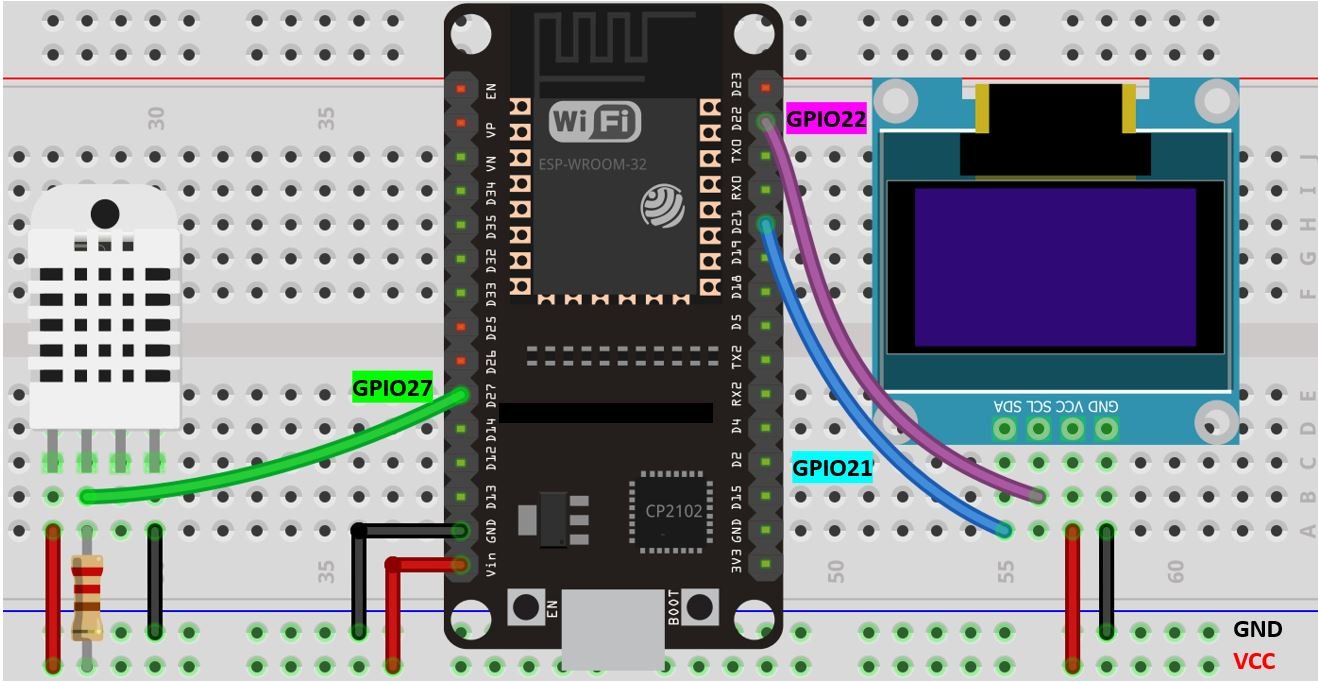
- The first pin is the power supply (VCC) pin. Connect it with the 3.3 volt pin of ESP32.
- Data out is the pin through which we get temperature and humidity samples from the DHT sensor. Connect this pin with GPIO27 of ESP32 and also connect the data pin with a 10k pull-up resistor. You can also use any appropriate digital pin of ESP32.
A Pull-up resistor is used to keep the data pin high for proper communication between the microcontroller and sensor. You can check the datasheet of DHT11 and DHT22 to get more information about it. DHT22 is also known by the name of AM2302.
- Third pin is not used
- Connect the fourth pin (GND) to the ground pin of the ESP32 board
Additionally, we will connect the VCC terminal of the OLED display to 3.3V, which will be common with the ESP32 board. The SCL of the display will be connected to the SCL pin of the ESP32 board, and the SDA of the display will be connected to the SDA of the ESP32.
All grounds will be common between the three devices.
Setting up Arduino IDE
We will use Arduino IDE to program our ESP32 development board. Thus, you should have the latest version of Arduino IDE. Additionally, you also need to install the ESP32 plugin.
Installing Libraries
For this project we will require three libraries:
- Adafruit SSD1306 library and Adafruit GFX library (To use the OLED display in our project, these two libraries will be required).
- DHT sensor library (As we are connecting the DHT22 sensor with the ESP32, we will have to use this library).
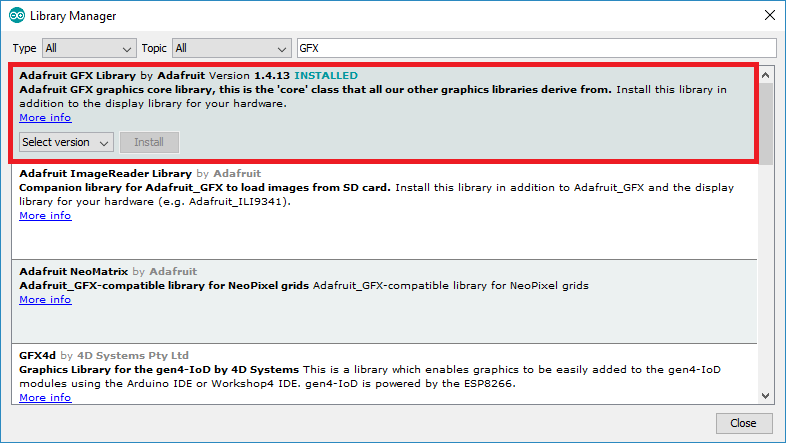
Open Arduino IDE and click on Sketch > Library > Manage Libraries
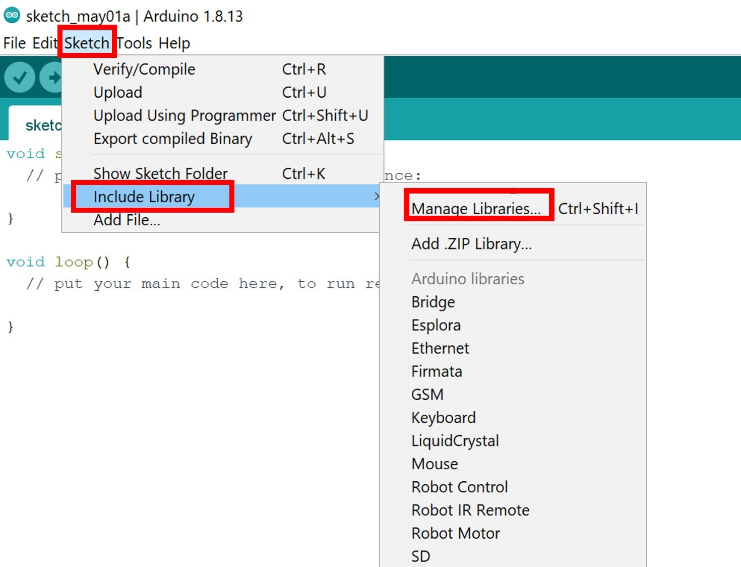
The following window will open up.

Type ‘SSD1306’ in the search tab and install the Adafruit SSD1306 OLED library.

We will also require the Adafruit GFX library which is a dependency for SSD1306. Type ‘Adafruit GFX’ in the search tab and install it as well.
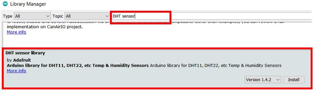
Additionally, search for ‘DHT sensor’ and install it as well.
After installing the libraries, restart your IDE.
ESP32 Code for obtaining the MAC Address
Open your Arduino IDE and go to File > New to open a new file. Copy the code given below in that file and save it.
#include "WiFi.h"

void setup(){
  Serial.begin(115200);
  WiFi.mode(WIFI_MODE_STA);
  Serial.println(WiFi.macAddress());
}

void loop(){

}
In the setup() function, we are first setting our ESP32 board in station mode. Then by using the WiFi.macAddress() method we will obtain the unique MAC address in our serial monitor.
Make sure you choose the correct board and COM port before uploading your code to the board. Go to Tools > Board and select ESP32 Dev Module. Next, go to Tools > Port and select the appropriate port through which your board is connected. In this case, we are using the ESP32 development board which is connected to COM5.
Click on the upload button to upload the code into the ESP32 development board. Press its ENABLE button after the sketch has been uploaded.

In your Arduino IDE, open up the serial monitor and you will be able to see the unique MAC address of your ESP32 module.
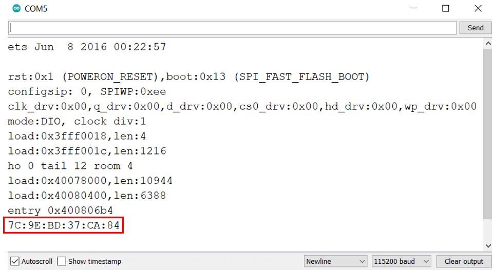
Obtain the MAC address for each ESP32 board and label it. We will need the unique MAC address of the receiver board while programming the sender ESP32 board.
ESP-NOW two-way communication ESP32 Code
Now, let us learn how to send sensor data from one ESP32 board to another, using the ESP-NOW protocol. We will use the simplest configuration of the two way communication, where two ESP32 boards are involved and each ESP32 board acts as the sender as well as the receiver. For this project, each ESP32 board will be programmed with an Arduino sketch containing the other board’s unique MAC address. This will indicate the receiver board to which the programmed board will send its sensor data.
Open your Arduino IDE and go to File > New to open a new file. Copy the code given below in that file and save it.
#include <esp_now.h>
#include <WiFi.h>
#include <Wire.h>
#include "DHT.h"
#include <Adafruit_GFX.h>
#include <Adafruit_SSD1306.h>

#define SCREEN_WIDTH 128
#define SCREEN_HEIGHT 64

Adafruit_SSD1306 display(SCREEN_WIDTH, SCREEN_HEIGHT, &Wire, -1);

#define DHTPIN 27
#define DHTTYPE DHT22
DHT dht(DHTPIN, DHTTYPE);

// REPLACE WITH THE MAC Address of your receiver
uint8_t broadcastAddress[] = {0x7C, 0x9E, 0xBD, 0x37, 0xCA, 0x84};

float temp;
float hum;

float sender_temperature;
float sender_humidity;

String success;

//Must match the receiver structure
typedef struct struct_message {
    float temp;
    float hum;
} struct_message;


struct_message DHT_Readings;
struct_message sender_Readings;

// Callback when data is sent
void data_sent(const uint8_t *mac_addr, esp_now_send_status_t status) {
  Serial.print("\r\nLast Packet Send Status:\t");
  Serial.println(status == ESP_NOW_SEND_SUCCESS ? "Delivery Success" : "Delivery Fail");
  if (status ==0){
    success = "Delivery Success :)";
  }
  else{
    success = "Delivery Fail :(";
  }
}

// Callback when data is received
void data_receive(const uint8_t * mac, const uint8_t *incomingData, int len) {
  memcpy(&sender_Readings, incomingData, sizeof(sender_Readings));
  Serial.print("Bytes received: ");
  Serial.println(len);
  sender_temperature = sender_Readings.temp;
  sender_humidity = sender_Readings.hum;
}

void setup() {

  Serial.begin(115200);
  dht.begin();

  if(!display.begin(SSD1306_SWITCHCAPVCC, 0x3C)) {
    Serial.println(F("SSD1306 allocation failed"));
    for(;;);
  }

  WiFi.mode(WIFI_STA);
  if (esp_now_init() != ESP_OK) {
    Serial.println("Error initializing ESP-NOW");
    return;
  }
  esp_now_register_send_cb(data_sent);

  esp_now_peer_info_t peerInfo;
  memcpy(peerInfo.peer_addr, broadcastAddress, 6);
  peerInfo.channel = 0;
  peerInfo.encrypt = false;
  if (esp_now_add_peer(&peerInfo) != ESP_OK){
    Serial.println("Failed to add peer");
    return;
  }
  // Register for a callback function that will be called when data is received
  esp_now_register_recv_cb(data_receive);
}

void loop() {
  getReadings();

  DHT_Readings.temp = temp;
  DHT_Readings.hum = hum;

  esp_err_t result = esp_now_send(broadcastAddress, (uint8_t *) &DHT_Readings, sizeof(DHT_Readings));

  if (result == ESP_OK) {
    Serial.println("Sent with success");
  }
  else {
    Serial.println("Error sending the data");
  }
  Display();
  delay(10000);
}
void getReadings(){
  hum = dht.readHumidity();
 temp = dht.readTemperature();
  if (isnan(hum) || isnan(temp)  ){
    Serial.println(F("Failed to read from DHT sensor!"));
    return;
}
}

void Display(){
  display.clearDisplay();
  display.setTextSize(1);
  display.setTextColor(WHITE);
  display.setCursor(0, 0);
  display.println("INCOMING READINGS");
  display.setCursor(0, 15);
  display.print("Temperature: ");
  display.print(sender_temperature);
  display.cp437(true);
  display.write(248);
  display.print("C");
  display.setCursor(0, 25);
  display.print("Humidity: ");
  display.print(sender_humidity);
  display.print("%");
  display.setCursor(0, 56);
  display.print(success);
  display.display();

  Serial.println("INCOMING READINGS");
  Serial.print("Temperature: ");
  Serial.print(sender_Readings.temp);
  Serial.println(" ºC");
  Serial.print("Humidity: ");
  Serial.print(sender_Readings.hum);
  Serial.println(" %");
  Serial.println();
}
How does the Code Work?
Including Libraries
Firstly, we will include the necessary libraries. For this project, we are using six of them. These include esp_now.h for the ESP-NOW communication protocol, WiFi.h for the ESP32 board to use the Wi-Fi functionalities. Wire.h will allow us to communicate through the I2C protocol that is required between the ESP32 and the DHT sensor. Additionally, we will also include the libraries that we installed previously (DHT.h, Adafruit_GFX.h and Adafruit_SSD1306.h for the DHT sensor and OLED display functionality.
#include <esp_now.h>
#include <WiFi.h>
#include <Wire.h>
#include "DHT.h"
#include <Adafruit_GFX.h>
#include <Adafruit_SSD1306.h>
Defining OLED Display
We will first define the width and height of our OLED display in pixels. We are using a 128×64 display hence the width will be 128 and the height will be 64.
Next, we will initialize the display by creating an object of Adafruit_SSD1306 and specifying the width, height, I2C instance (&Wire), and -1 as parameters inside it.’ -1′ specifies that the OLED display which we are using does not have a RESET pin. If you are using the RESET pin then specify the GPIO through which you are connecting it with your development board.
#define SCREEN_WIDTH 128
#define SCREEN_HEIGHT 64

Adafruit_SSD1306 display(SCREEN_WIDTH, SCREEN_HEIGHT, &Wire, -1);
Defining DHT Sensor
The following lines of code specify the type of DHT sensor and the GPIO pin of the ESP32 board that will be connected to the data pin of the sensor. We are using GPIO27, but you can use any appropriate GPIO pin.
#define DHTPIN 27
#define DHTTYPE DHT22
DHT dht(DHTPIN, DHTTYPE);
Specifying Receiver MAC Address
Next, we will specify the MAC Address of the ESP32 board which will act as the receiver. Replace the address with the unique MAC address of your own ESP32 board. You can use the sketch which was given previously, to find the MAC address of your module.
*Specify the MAC Address of the receiver board. For programming ESP32 #1, specify the MAC address of ESP32 #2 and vice versa.
uint8_t broadcastAddress[] = {0x7C, 0x9E, 0xBD, 0x37, 0xCA, 0x84};Defining Variables
Now we will define some variables that we will use later on in the program code. These include the floating variables (temp and hum) that will save sensor values obtained from the DHT sensor which we will send over to the other ESP32 board.
Moreover, the ‘sender_temperature’ and ‘sender_humidity’ contain the incoming sensor values from the other ESP32 board.
float temp;
float hum;

float sender_temperature;
float sender_humidity;
Defining structure for sending data
Now, we will define a structure named ‘struct_message.’ Inside the structure, we will initialize the variables which will hold our data that we will transmit to the receiver board via ESP-NOW. These will be the temperature and humidity readings obtained from the DHT sensor.
typedef struct struct_message {
    float temp;
    float hum;
} struct_message;
Next, we will create new instances of type struct_message and call them ‘DHT_Readings’ and ‘sender_Readings.’ These will be used later on in the sketch to acquire the data and transmit it accordingly. The ‘DHT_Readings’ will save the sensor readings that we will send to the other board. Whereas the ‘sender_Readings’ will save sensor readings that we be transmitted from the other board.
struct_message DHT_Readings;
struct_message sender_Readings;
data_sent()
The data_sent() function acts as the callback function which we will define now. It will be used as a parameter when we register this callback function for sending messages. This function prints whether the message was successfully delivered or not on the serial monitor whenever a message is sent from the ESP32 board.
void data_sent(const uint8_t *mac_addr, esp_now_send_status_t status) {
  Serial.print("\r\nLast Packet Send Status:\t");
  Serial.println(status == ESP_NOW_SEND_SUCCESS ? "Delivery Success" : "Delivery Fail");
  if (status ==0){
    success = "Delivery Success :)";
  }
  else{
    success = "Delivery Fail :(";
  }
}
data_receive()
The data_receive() function acts as the callback function which we will define now. It will be used as a parameter when we will register this callback function for receiving messages. This prints the message on the serial monitor whenever a message is received from the other ESP32. It prints the length of the message in bytes in the serial monitor. Then the incoming temperature (sender_Readings.temp) and humidity readings (sender_Readings.hum) are saved in their respective variables that we defined earlier: ‘sender_temperature’ and ‘sender_humidity.’
void data_receive(const uint8_t * mac, const uint8_t *incomingData, int len) {
  memcpy(&sender_Readings, incomingData, sizeof(sender_Readings));
  Serial.print("Bytes received: ");
  Serial.println(len);
  sender_temperature = sender_Readings.temp;
  sender_humidity = sender_Readings.hum;
}
setup()
Inside the setup() function, we will open a serial connection at a baud rate of 115200. Additionally, we will initiate the connection with the DHT sensor by using the begin() method on the dht object.
Serial.begin(115200);
dht.begin();
Moreover, we will also initialize the OLED display by using display.begin(). Make sure you specify the correct address of your display. In our case, it is 0X3C.
if(!display.begin(SSD1306_SWITCHCAPVCC, 0x3C)) {
    Serial.println(F("SSD1306 allocation failed"));
    for(;;);
  }
We will set up the ESP32 receiver board in station mode as well.
WiFi.mode(WIFI_STA);Initialize ESP-NOW
The following lines of code will initialize the ESP-NOW protocol. In case of an unsuccessful connection, the serial monitor will display ‘Error initializing ESP-NOW.’
if (esp_now_init() != ESP_OK) {
    Serial.println("Error initializing ESP-NOW");
    return;
  }
Now we will register the data_sent() function as the callback function. This will make sure that whenever a message will be sent, the data_sent() function will be called.
esp_now_register_send_cb(data_sent);The following lines of code will pair the two ESP32 boards.
 esp_now_peer_info_t peerInfo;
  memcpy(peerInfo.peer_addr, broadcastAddress, 6);
  peerInfo.channel = 0;
  peerInfo.encrypt = false;
  if (esp_now_add_peer(&peerInfo) != ESP_OK){
    Serial.println("Failed to add peer");
    return;
  }
Now we will register the data_receive() function as the callback function as shown below. This will make sure that whenever a message will be received from the other board, the data_receive() function will be called.
esp_now_register_recv_cb(data_receive);loop()
Inside the loop() function, we will first call the getReadings() function. Firstly, through dht.readHumidity(), the humidity reading will get saved in the variable ‘hum.’ Likewise, for temperature, the sensor reading will get saved in the variable ‘temp.’ Additionally, if the connection between the ESP32 board and the DHT sensor is incorrect or the values are not being accessed properly then an error message will be printed. This will help us in debugging our circuit or a possible issue in the initialization of the sensor.
void getReadings(){
  hum = dht.readHumidity();
 temp = dht.readTemperature();
  if (isnan(hum) || isnan(temp)  ){
    Serial.println(F("Failed to read from DHT sensor!"));
    return;
}
}
Next, update the DHT_Readings structure with the values which we just obtained from the DHT sensor saved in ‘temp’ and ‘hum.’
DHT_Readings.temp = temp;
DHT_Readings.hum = hum;
Now using ESP-NOW protocol, we will send these readings to the other ESP32 board. If sent successfully, the serial monitor will display ‘Sent with success’ otherwise it will display ‘Error sending the data.’
 esp_err_t result = esp_now_send(broadcastAddress, (uint8_t *) &DHT_Readings, sizeof(DHT_Readings));

  if (result == ESP_OK) {
    Serial.println("Sent with success");
  }
  else {
    Serial.println("Error sending the data");
  }
Displaying Readings on OLED and Serial Monitor
Lastly, we will call the Display() function. This function will display the sensor readings obtained from the other ESP32 board in the serial monitor and the OLED display. We will clear the buffer by using clearDisplay() on the Adafruit_SSD1306 object. Then we will set the size of the text using setTextSize() and pass the size as a parameter inside it. 1 denotes the smallest size and it increases relatively after incrementing it.
We will use the setCursor() function to specify the x and y-axis positions from where the text should start. In this case, we have passed (0,0) as the parameters, so the text will start from the upper left corner. Then, using println(), we will display the desired text on the OLED. We will also set the cursor to different positions in order to display the temperature and humidity readings. Finally, we will call the display() function on the display object to ensure that the text is shown on the OLED.
We will also display the readings in the serial monitor as well by using Serial.print().
void Display(){
  display.clearDisplay();
  display.setTextSize(1);
  display.setTextColor(WHITE);
  display.setCursor(0, 0);
  display.println("INCOMING READINGS");
  display.setCursor(0, 15);
  display.print("Temperature: ");
  display.print(sender_temperature);
  display.cp437(true);
  display.write(248);
  display.print("C");
  display.setCursor(0, 25);
  display.print("Humidity: ");
  display.print(sender_humidity);
  display.print("%");
  display.setCursor(0, 56);
  display.print(success);
  display.display();

  Serial.println("INCOMING READINGS");
  Serial.print("Temperature: ");
  Serial.print(sender_Readings.temp);
  Serial.println(" ºC");
  Serial.print("Humidity: ");
  Serial.print(sender_Readings.hum);
  Serial.println(" %");
  Serial.println();
}
Demonstration
Replicate the code given above in another file and replace the receiver MAC address with that of the other ESP32 board. Now upload the Arduino sketches onto their respective ESP32 boards. Choose the correct board and COM port before uploading your code to the ESP32 boards. Go to Tools > Board and select ESP32 Dev Module.

Next, go to Tools > Port and select the appropriate port through which your board is connected.

Click on the upload button to upload the code into the ESP32 board. After you have uploaded your code to the board press its ENABLE button.
Next, follow the same steps and upload the second sketch to the other ESP32 module but remember to replace the receiver’s MAC address. Make sure you choose the correct COM port through which it is connected. Notice, that both of the boards will be connected to different COM ports so select the COM port accordingly. Click on the upload button to upload the code into the ESP32 board. After you have uploaded your code to the board press its ENABLE button.
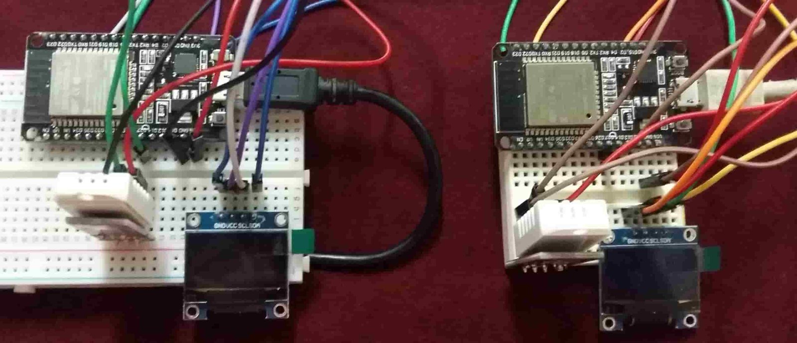
Both the OLED displays will start displaying the sensor readings obtained from the other board.
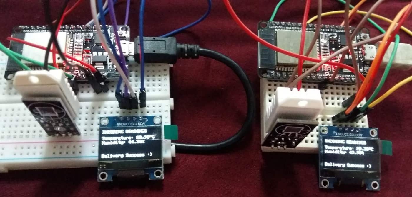
Here you can clearly view the sensor readings in one of the OLED displays.

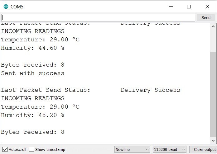
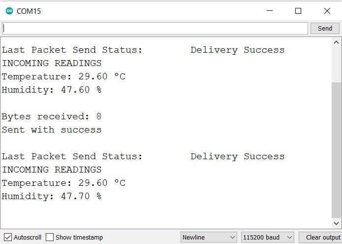
Now, open both the serial monitors. You will be able to see the messages being displayed on both boards.
Conclusion
In conclusion, we have learned about the ESP-NOW two-way communication protocol. As an example, we communicated DHT sensor data between two ESP32 boards using ESP-NOW wirelessly and displayed them on an OLED display in a fast and convenient manner. Although we have used two ESP32 boards to communicate with each other, you can also use ESP-NOW for communication between several ESP32 boards.
You may also like to read:
- ESP32 ESP-NOW Getting Started Tutorial with Arduino IDE
- ESP32 ESP-NOW Send Data to Multiple boards (One to Many Communication)
- ESP32 ESP-NOW Receive Data from Multiple boards (Many to One Communication)
- ESP32 ESP-NOW and Wi-Fi Web Server using Arduino IDE
- ESP32 ESP-NOW Send and Receive Encrypted Messages
So what Wifi Library did you use?
#include
Could belong to any of the wifi library files available on the Arduino platform.
You have made it clear which adafruit libraries to install but the wifi library and
author is paramount.
It would be a good idea to include a comments section at the top of your
code which libraries you are using.
Good circuit but unusuable unless you are succinct with libaries.