In this tutorial, we will build an IoT based motion detection project using an HC-SR501 PIR motion sensor, ESP8266 NodeMCU with an email alert feature. Our motion detection project will be linked with a web server that will update whenever motion will be detected, specifying the exact date and time of the detection. Additionally, we will use the IFTTT web service to generate an email alert to notify users about motion detection.
ESP8266 IoT Motion Detection Web Server Overview
Our ESP8266 Node MCU will be connected with an LED and a PIR motion sensor to detect movement.

Our aim is to design an IoT motion detection project that does three things whenever motion is detected. This includes turning the LED ON which is connected with ESP8266 NodeMCU and PIR sensor, updating the web page with motion detection at exact time and date, and lastly sending an email notification alerting that motion has been detected at the occurred time.

Note: You can also use a buzzer or bell instead of an LED as an indicator.
In this guide we will learn how to build the web page for motion detection as well as learn how to configure IFTTT web service to generate email notifications.
This guide is divided into the following sections:
- Introduction of PIR sensor, working and connection diagram
- Configuring IFTTT for email alerts
- Arduino Sketch and Demonstration
PIR Motion Sensor
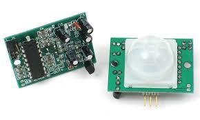
There are many PIR sensors available in the market but we are using passive PIR motion sensors in this project. It can detect a human motion within a range of 10m very easily. It has three pins and the function of each pin is described below:
- GND: It is a ground pin and you should connect it with the ground of your ESP8266 board.
- VDD: It is a power supplier pin and you should connect it with Vin of our ESP8266 board.
- Output: It is an output pin of the PIR sensor. Basically, we get output from this pin. We will connect it with one of the input GPIO pins of our ESP8266 board.
PIR Motion Sensor Working
PIR sensor is a low-cost motion detector sensor. It is a passive motion sensor that means it can only detect something around it and it cannot transmit anything. Whenever there is a motion around the sensor, it will detect the heat of the human body and produces a high output logic 1 at the output of the sensor. Every object emits infrared rays when they are heated and on the same principle, the human body emits IR rays due to body heat. Hence, whenever the motion sensor detects the human body around it, its output becomes high. We can also adjust the sensitivity of this sensor by changing the variable resistors available on the sensor. One variable resistor is for sensitivity adjustment of distance and another variable resistor is for sensitivity adjustment of time that is the amount of time for which the output should be high.
Connection Diagram
The following components are required:
- ESP8266 development board
- One PIR Sensor
- One 5mm LED
- One 220 ohm resistor
- Breadboard
- Connecting Wires
ESP8266 IOT Based Motion Detection Circuit Diagram
Assemble your circuit as shown in the diagram below:
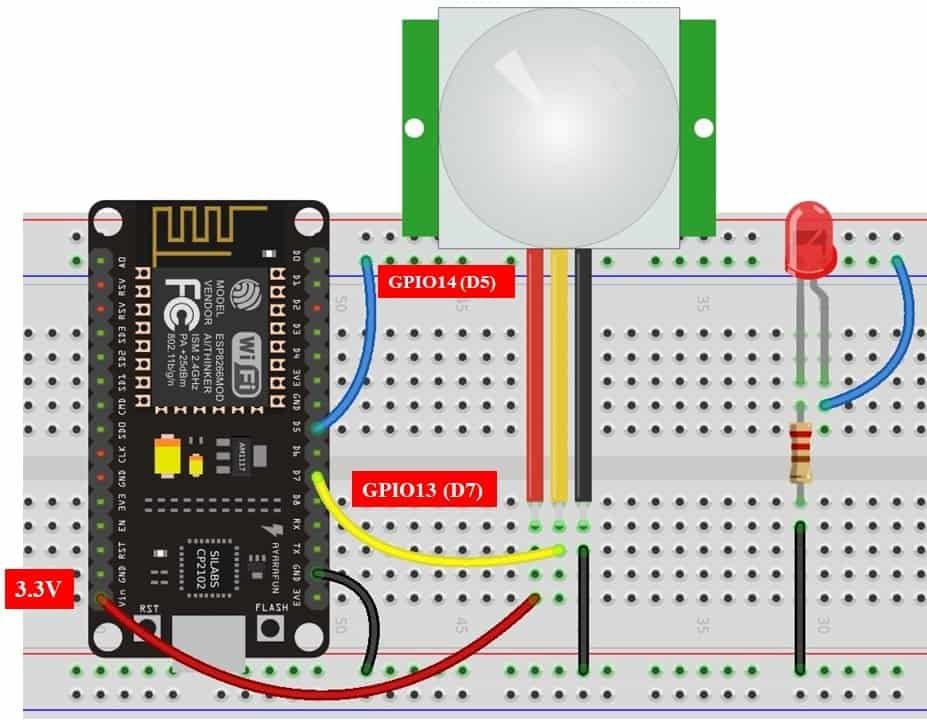
In the above schematic, we can see that GPIO14 is connected with the anode pin of LED, and the cathode pin is connected with the common ground through the 220 ohm resistor.
The PIR Sensor which we are using in this tutorial consists of three pins. Two of them are power supply pins such as VCC and ground pins. We can power PIR motion sensor directly from the ESP8266 3.3V power pin as shown in the above schematic diagram. The centre pin is the output pin which provides an active high pulse whenever motion is detected. Otherwise, this pin remains active low. That means a rising edge occurs when a PIR sensor detects motion. Here we have connected the output pin of the sensor with GPIO13. All are the grounds are in common.
In previous articles, we have used PIR motion sensor with both ESP32 and ESP8266 in Arduino IDE as well as in MicroPython. You can view the articles below:
- MicroPython: Interrupts with ESP32 and ESP8266 – PIR Sensor Interfacing Example
- ESP8266 Interrupts and Timers Arduino IDE – PIR Motion Sensor Example
- ESP32 Interrupts and Timers with PIR Sensor using Arduino IDE
Configuring IFTTT Web service
IFTTT means ‘If this, then that.’ It is an open-source service that gives the user the freedom to program a response to an event according to their likes. We can create an applet which are chains of conditional statements by a combination of several app services and add triggering parameters. For our project, we will be using this service, to send email alerts whenever motion is detected. To work with this web service, we will have to follow a series of steps to ensure the proper functionality.
Creating an Account
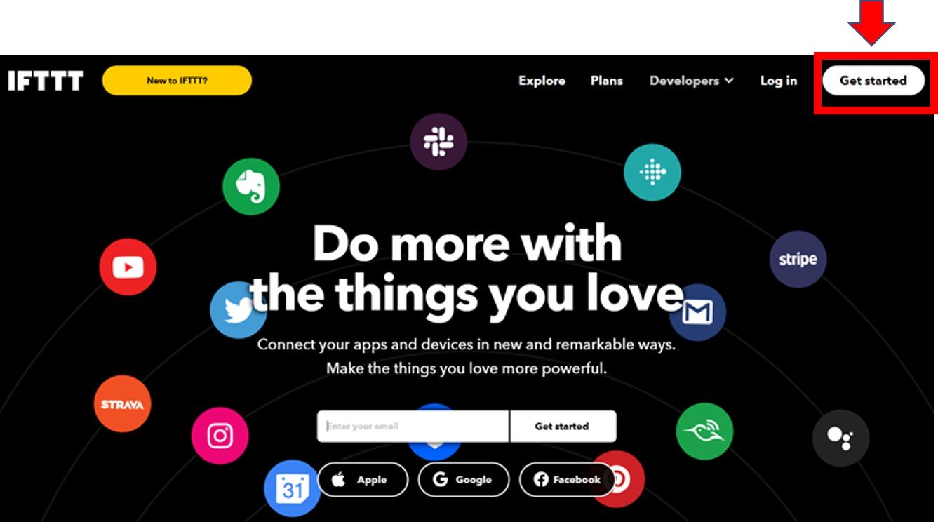
Although the IFTTT service is free to use, we will have to create an account. First go to the following website: https://ifttt.com/
The following window will appear. Click on the ‘Get Started’ button.
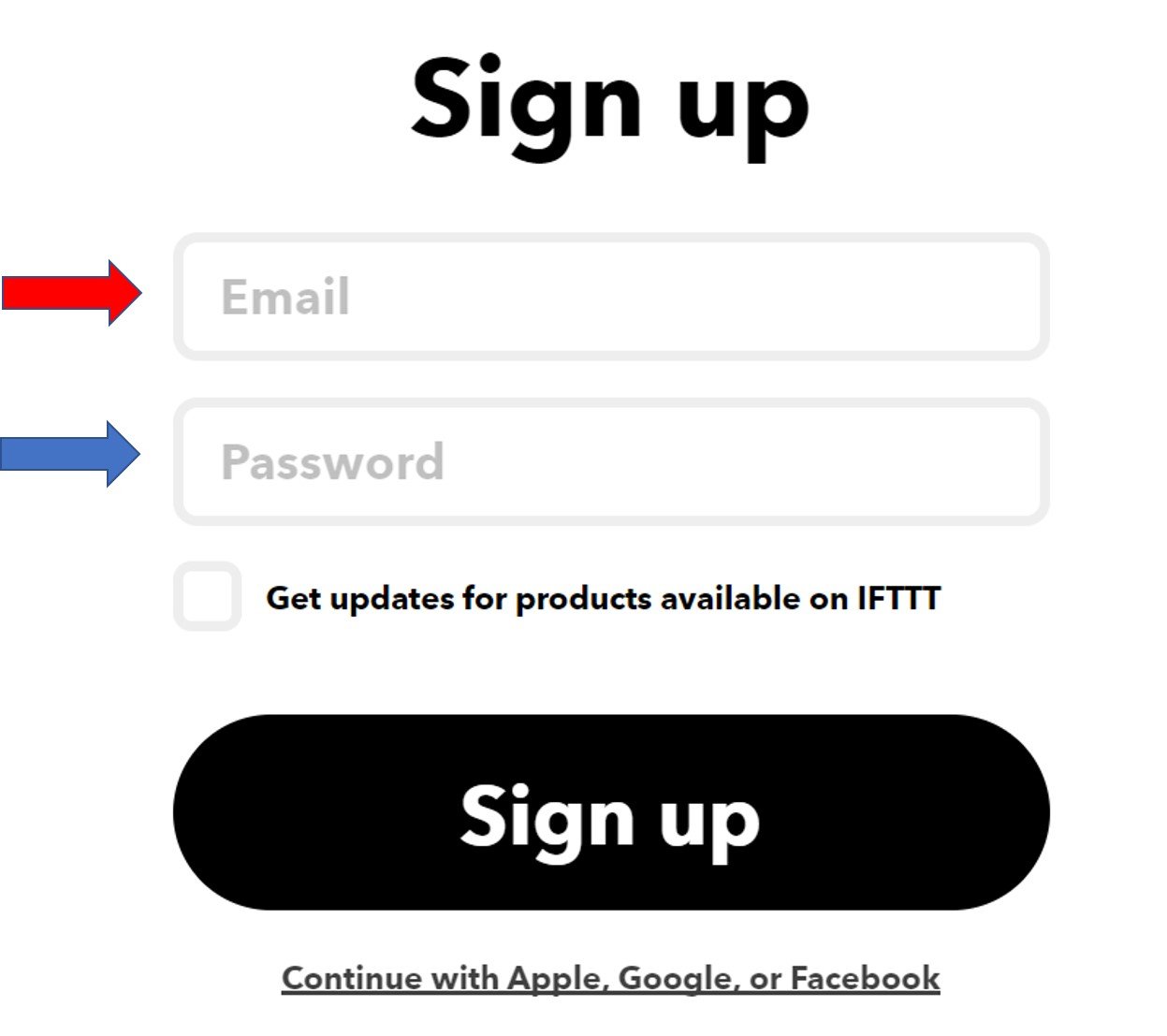
The following window will appear. You can select any one from these three options (Apple, Google or Facebook) to connect. Or you can simply ‘sign up’ with your own given email. We will be following this scheme.
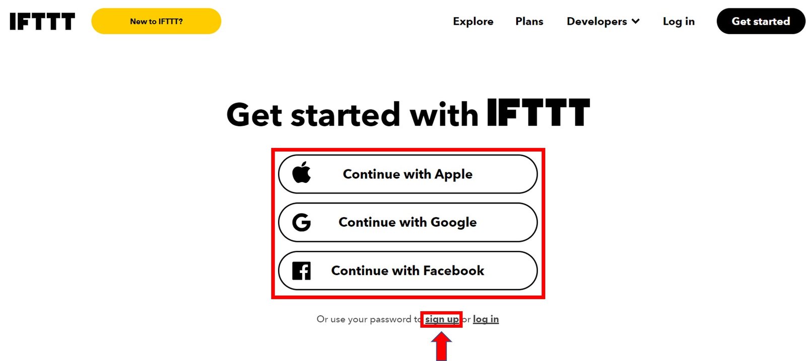
Click the ‘sign up’ tag. You will see the following window pop up. Enter your email address and password to start working in IFTTT. This whole process is free of cost for the first three applets.
Creating an Applet
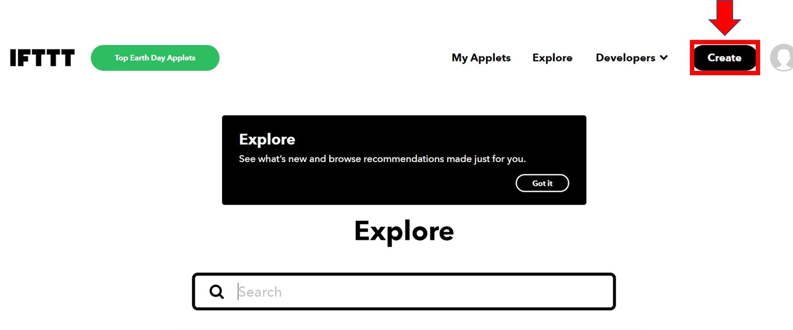
After you have created your account, we will be directed to the page where we will create our applet. Click on ‘Create.’
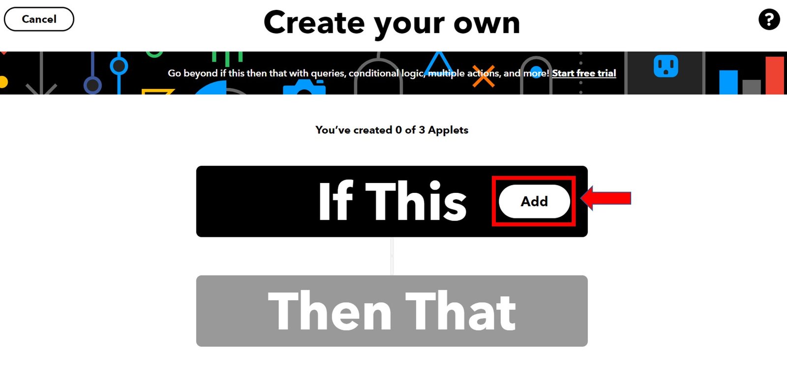
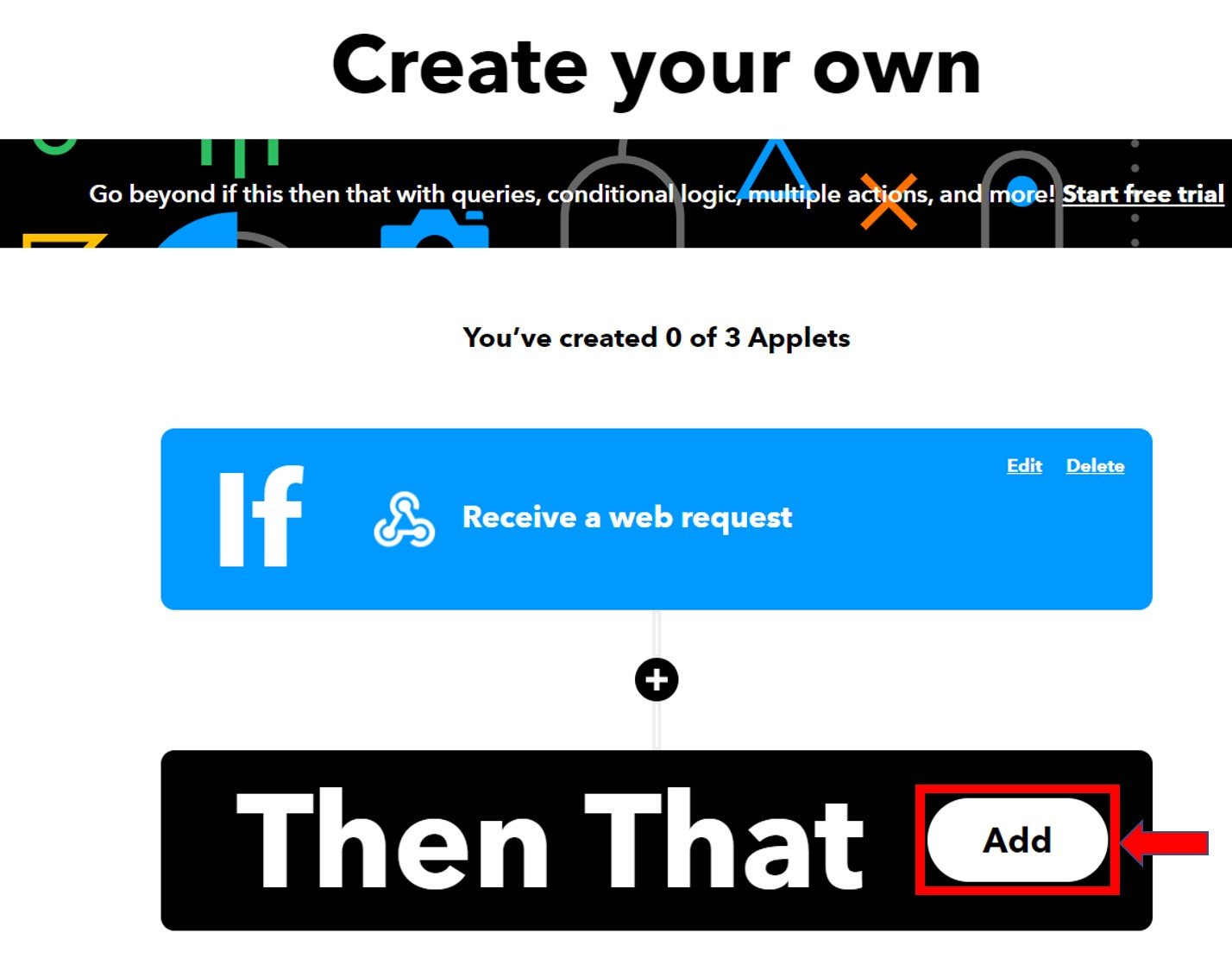
The following window opens up. Click the following Add button in the ‘If This’ section.
Another page will open in which we will have to choose our service. There is a lot of options to choose from. Write down ‘webhooks’ in the search option and its icon will appear:

Select Trigger
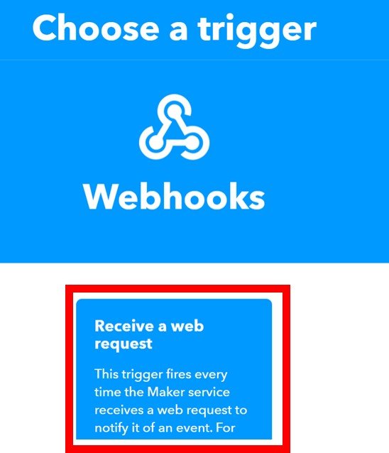
Next, choose the trigger as: ‘Receive a web request’ by clicking on it. Whenever webhooks will receive a web request, some action will take place. This we will define in the ‘THAT’ section.
After clicking the Receive a web request, the following window will open up. We will write down Motion_Detection as the event name for the web request. You can use any other name of your choice. Click ‘Create Trigger’ button.

After the trigger is created, we are taken back to the web page where we first added the service for the ‘IF THIS’ section. Now we will click the ADD button for the ‘THEN THAT’ section.
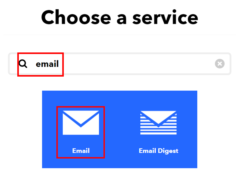
Now we will choose the service. We have to choose what will happen if a web request is received. We will type ‘email’ in the search option and click on its icon. This is because we want to receive email notification whenever a web request is received.
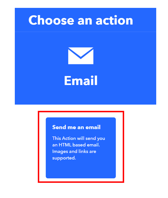
The following page opens up. Choose ‘Send me an email’ to proceed further.
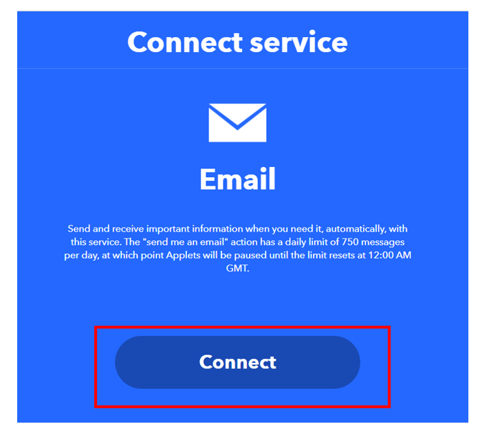
Click on the ‘Connect’ button as shown below.
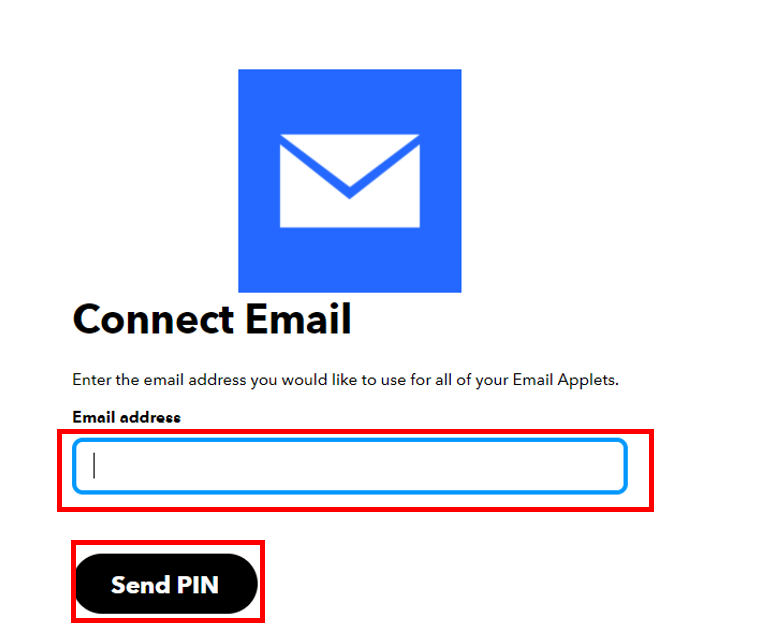
Next, write down your email address and click ‘Send Pin’ as shown below:
After you successfully enter the PIN, a new window will open up. Complete the action fields by specifying the subject and body of the email. Afterwards, click ‘Create Action.’

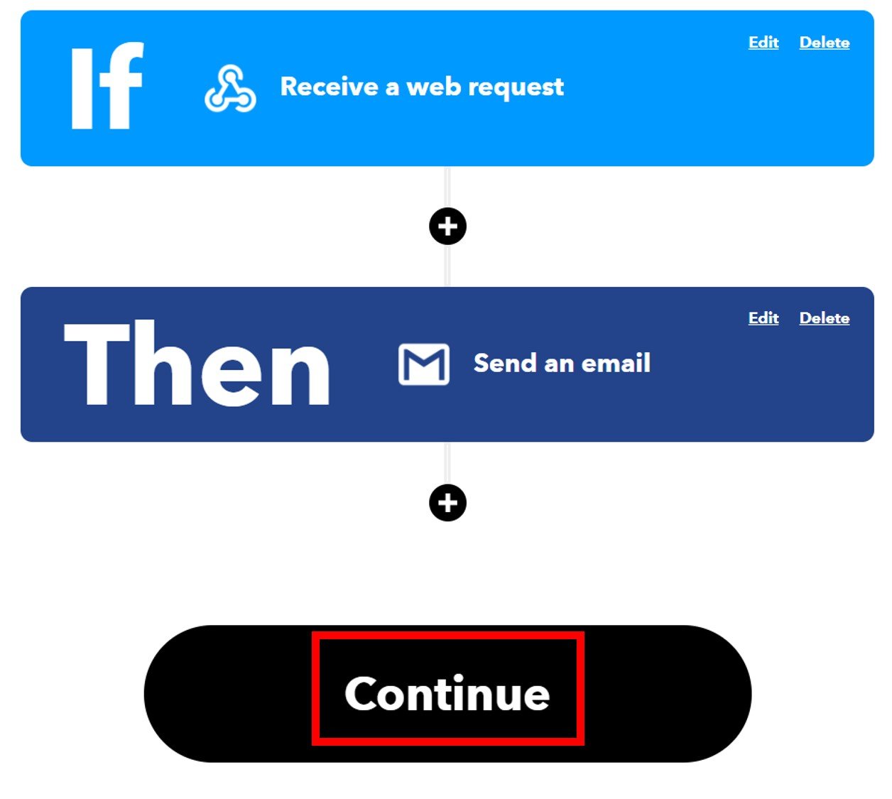
After we have created the action, we will be guided towards the initial web page of IFTTT. Click ‘Continue’ to proceed.
After this click the Finish button. Make sure to turn ON the notifications when the applet is running.
You have successfully created the applet as shown below.

Obtaining the Private Key
Before we proceed further with our project, we want to access our private key. This is important as it will be required while programming our ESP8266 board.
Go to your applet and select “My Services” or open a webpage with the link: ifttt.com/my_services. The following windows will appear. Afterward, click on Webhooks.

This will take you to the following web page. Click on ‘Documentation.’

You will receive a key that should be secure with you.

You may also like to read about other project we created with IFTTT:
- ESP32/ESP8266: Publish Sensor Readings to Google Sheets via IFTTT
- ESP32 HTTP POST using Arduino IDE (ThingSpeak and IFTTT)
- MicroPython: Send Sensor Readings via Email (IFTTT) with ESP32 and ESP8266
- Send Email Alert Based on Temperature Threshold and Update Threshold value with ESP32 Web Server
ESP8266 Arduino Sketch for IoT Motion Detection Project
Before we proceed further, you should make sure that you have the latest version of Arduino IDE installed on your system. Moreover, you should also install an ESP8266 add-on in Arduino IDE. If your IDE does not have the plugin installed you can visit the link below:
Installing ESP8266 library in Arduino IDE
There will be no need to install additional libraries for this project as the ESP8266 Arduino core already comes with the libraries which we require.
Open your Arduino IDE and go to File > New to open a new file. Copy the code given below in that file. Make sure to replace your network credentials and the private key for Webhooks.
#include <ESP8266WiFi.h>
#include <WiFiClient.h>
#include <ESP8266WebServer.h>

const char* ssid = "Your_SSID";
const char* password = "Your_Password";

const char *host = "maker.ifttt.com";
const char *privateKey = "gkb_HtIpE-FeOWMH20obLTvUR7_fPipDyj*********";

ESP8266WebServer server(80);
void send_event(const char *event);

int led_pin = 14;
int sensor_pin = 13;
String Message;

const char MAIN_page[] PROGMEM = R"=====(
<!doctype html>
<html>
<head>
<title>IoT Motion detector</title>
  <meta name="viewport" content="width=device-width, initial-scale=1">
  <h1 style="text-align:center; color:blue;font-size: 2.5rem;">IoT Motion Detector</h1>
  <style>
  canvas{
    -moz-user-select: none;
    -webkit-user-select: none;
    -ms-user-select: none;
  }
  #data_table {
    font-family: New Times Roman;
    border-collapse: collapse;
    width: 100%;
    text-align: center;
    font-size: 0.8rem;
  }
  #data_table td, #data_table th {
    border: 3px solid #ddd;
    padding: 15px;
  }
  #data_table tr:nth-child(even){background-color: #faffff;}
  #data_table tr:hover {background-color: #faffff;}
  #data_table th {
    padding-top: 20px;
    padding-bottom: 20px;
    text-align: center;
    background-color: #190775;
    color: white;
  }
  </style>
</head>
<body>
<div>
  <table id="data_table">
    <tr><th>Time</th><th>Activity</th></tr>
  </table>
</div>
<br>
<br>
<script>

var Avalues = [];
var dateStamp = [];

setInterval(function() {
  getData();
}, 3000);
function getData() {
  var xhttp = new XMLHttpRequest();
  xhttp.onreadystatechange = function() {
    if (this.readyState == 4 && this.status == 200) {
  var date = new Date();
  var txt = this.responseText;
  var obj = JSON.parse(txt);
      Avalues.push(obj.Activity);
      dateStamp.push(date);

    var table = document.getElementById("data_table");
    var row = table.insertRow(1);
    var cell1 = row.insertCell(0);
    var cell2 = row.insertCell(1);
    cell1.innerHTML = date;
    cell2.innerHTML = obj.Activity;
    }
  };
  xhttp.open("GET", "read_data", true);
  xhttp.send();
}
</script>
</body>
</html>

)=====";
void handleRoot() {
 String s = MAIN_page;
 server.send(200, "text/html", s);
}
void read_data() {
  int state = digitalRead(sensor_pin);
  delay(500);
  Serial.print(state);
    if(state == HIGH){
    digitalWrite (led_pin, HIGH);
    delay(1000);
    digitalWrite (led_pin, LOW);
    Message = "Motion Detected";
    String data = "{\"Activity\":\""+ String(Message) +"\"}";
    server.send(200, "text/plane", data);
    send_event("Motion_Detection");
    Serial.println("Motion detected!");
    }
}
void setup() {
 Serial.begin(115200);

 WiFi.begin(ssid, password);
 while (WiFi.status() != WL_CONNECTED) {
 delay(500);
 Serial.print("Connecting...");
 }
 Serial.println("");
 Serial.println("Successfully connected to WiFi.");
 Serial.println("IP address is : ");
 Serial.println(WiFi.localIP());

 server.on("/", handleRoot);
 server.on("/read_data", read_data);
 server.begin();

 pinMode(sensor_pin, INPUT);
 pinMode(led_pin, OUTPUT);
 digitalWrite (led_pin, LOW);
}
void loop(){
  server.handleClient();
}
void send_event(const char *event)
{
  Serial.print("Connecting to ");
  Serial.println(host);

  WiFiClient client;
  const int httpPort = 80;
  if (!client.connect(host, httpPort)) {
    Serial.println("Connection failed");
    return;
  }

  String url = "/trigger/";
  url += event;
  url += "/with/key/";
  url += privateKey;
  Serial.print("Requesting URL: ");
  Serial.println(url);
  client.print(String("GET ") + url + " HTTP/1.1\r\n" +
               "Host: " + host + "\r\n" +
               "Connection: close\r\n\r\n");
  while(client.connected())
  {
    if(client.available())
    {
      String line = client.readStringUntil('\r');
      Serial.print(line);
    } else {
      delay(50);
    };
  }
  Serial.println();
  Serial.println("Closing Connection");
  client.stop();
}
How the Code Works?
The first step is to include the necessary libraries. Include the following ESP8266 libraries for the proper functionality of the project.
#include <ESP8266WiFi.h>
#include <WiFiClient.h>
#include <ESP8266WebServer.h>
Next, we will create two global variables, one for the SSID and the other for the password. These will hold our network credentials which will be used to connect to our wireless network. Replace both of them with your credentials to ensure a successful connection.
const char* ssid = "Your_SSID";
const char* password = "Your_Password";
The next step is very important. We will create two global variables. One will hold the IFTTT private key which we previously saved when we created our applet. This will be unique for your created applet. The other variable will hold the server (host) which will be identical for everyone.
const char *host = "maker.ifttt.com";
const char *privateKey = "gkb_HtIpE-FeOWMH20obLTvUR7_fPipDyj*********";
In the following line of code, we will create an object of ESP8266WebServer called server() and specify 80 as a parameter inside it. This will be the default port where the object will listen for HTTP requests.
ESP8266WebServer server(80);
Then we will define some variables. First, the integer variable ‘led_pin’ to hold the ESP8266 GPIO pin where the LED will connected. Also, we will specify the PIR sensor middle pin as well. It is GPIO14 for the LED and GPIO13 for the PIR sensor in our case. You can use any appropriate GPIO pin.
Moreover, we will also create a string variable called ‘message’ that will save the text that we want to display on the web server after motion gets detected.
int led_pin = 14;
int sensor_pin = 13;
String Message;
Building the Web Page
The following lines of code include the HTML, CSS and JavaScript required for building the web page.
const char MAIN_page[] PROGMEM = R"=====(
<!doctype html>
<html>
<head>
<title>IoT Motion detector</title>
  <meta name="viewport" content="width=device-width, initial-scale=1">
  <h1 style="text-align:center; color:blue;font-size: 2.5rem;">IoT Motion Detector</h1>
  <style>
  canvas{
    -moz-user-select: none;
    -webkit-user-select: none;
    -ms-user-select: none;
  }
  #data_table {
    font-family: New Times Roman;
    border-collapse: collapse;
    width: 100%;
    text-align: center;
    font-size: 0.8rem;
  }
  #data_table td, #data_table th {
    border: 3px solid #ddd;
    padding: 15px;
  }
  #data_table tr:nth-child(even){background-color: #faffff;}
  #data_table tr:hover {background-color: #faffff;}
  #data_table th {
    padding-top: 20px;
    padding-bottom: 20px;
    text-align: center;
    background-color: #190775;
    color: white;
  }
  </style>
</head>
<body>
<div>
  <table id="data_table">
    <tr><th>Time</th><th>Activity</th></tr>
  </table>
</div>
<br>
<br>
<script>

var Avalues = [];
var dateStamp = [];

setInterval(function() {
  getData();
}, 3000);
function getData() {
  var xhttp = new XMLHttpRequest();
  xhttp.onreadystatechange = function() {
    if (this.readyState == 4 && this.status == 200) {
  var date = new Date();
  var txt = this.responseText;
  var obj = JSON.parse(txt);
      Avalues.push(obj.Activity);
      dateStamp.push(date);

    var table = document.getElementById("data_table");
    var row = table.insertRow(1);
    var cell1 = row.insertCell(0);
    var cell2 = row.insertCell(1);
    cell1.innerHTML = date;
    cell2.innerHTML = obj.Activity;
    }
  };
  xhttp.open("GET", "read_data", true);
  xhttp.send();
}
</script>
</body>
</html>

)=====";
We will start with the title of the web page. The <title> tag will indicate the beginning of the title and the </title> tag will indicate the ending. In between these tags, we will specify “ IoT Motion detector ” which will be displayed in the browser’s title bar.
<title>IoT Motion detector</title>Next, we will create a meta tag to make sure our web server is available for all browsers e.g., smartphones, laptops, computers etc.
<meta name="viewport" content="width=device-width, initial-scale=1">We will insert the heading as “IoT Motion Detector” in blue colour and specify the font size and text allignment.
<h1 style="text-align:center; color:blue;font-size: 2.5rem;">IoT Motion Detector</h1>Next, we will include the <style> </style> tags which mark the beginning and end of the CSS styling file. We will set the display text to font type Times New Roman and align it in the centre of the webpage. For all the different texts, the font size, font type, colour, positioning and everything relating to the overall visuals of the web page will be is specified. This section of code shows the CSS styling which we will incorporate in our web page.
<style>
  canvas{
    -moz-user-select: none;
    -webkit-user-select: none;
    -ms-user-select: none;
  }
  #data_table {
    font-family: New Times Roman;
    border-collapse: collapse;
    width: 100%;
    text-align: center;
    font-size: 0.8rem;
  }
  #data_table td, #data_table th {
    border: 3px solid #ddd;
    padding: 15px;
  }
  #data_table tr:nth-child(even){background-color: #faffff;}
  #data_table tr:hover {background-color: #faffff;}
  #data_table th {
    padding-top: 20px;
    padding-bottom: 20px;
    text-align: center;
    background-color: #190775;
    color: white;
  }
  </style>
Our IoT Detection web server will display the data in the form of a table. It will have two columns. The first columns will show the Date/Time when the motion will be detected. The second column will display the status of the motion detection which we will specify as Activity.
<table id="data_table">
    <tr><th>Time</th><th>Activity</th></tr>
  </table>
JavaScript
Inside the <script> </script> tags we will include the JavaScript. It includes the getData() function as defined below. This function takes in no parameters. It is responsible to acquire the PIR motion detection data from ESP8266 board. This will be used to update the web server by adding the table contents. The current date and time of motion detection will get added in the first cell and the activity in the second cell. Inside this function we use the XMLHttpRequest. This will allow us to make an HTTP request in JavaScript. This will make sure that the web server updates automatically with out the need to reload it.
function getData() {
  var xhttp = new XMLHttpRequest();
  xhttp.onreadystatechange = function() {
    if (this.readyState == 4 && this.status == 200) {
  var date = new Date();
  var txt = this.responseText;
  var obj = JSON.parse(txt);
      Avalues.push(obj.Activity);
      dateStamp.push(date);

    var table = document.getElementById("data_table");
    var row = table.insertRow(1);
    var cell1 = row.insertCell(0);
    var cell2 = row.insertCell(1);
    cell1.innerHTML = date;
    cell2.innerHTML = obj.Activity;
    }
  };

xhttp.open("GET", "read_data", true);
  xhttp.send();
We will initialize the request by using the xhttp.open() method. Inside it we will pass on three arguments. The first argument specifies the type of HTTP method which is GET in our case. The second argument is the URL. In our case, it is the read_data URL. The last argument is true which specifies that the request is asynchronous.
xhttp.open("GET", "read_data", true); Lastly, we will use xhr.send() to open the connection. This will send the request to the server.
xhttp.send();handleRoot()
The handleRoot() function takes in no parameters. It is responsible for ESP8266 handling the /root URL. We will configure the root / URL where our server will listen to HTTP GET requests.
The handling function will respond to the client by using the send() method on the server. This method will take in three parameters. The first is 200 which is the HTTP status code for ‘ok’. The second is “text/html” which will correspond to the content type of the response. The third input is the text saved on the ‘s’ variable which will be sent as the response. It is the MAIN_page.
void handleRoot() {
 String s = MAIN_page;
 server.send(200, "text/html", s);
}
read_data()
The read_data() function also takes in no parameters. It acquires the sensor data from the PIR sensor and saves it in the integer variable ‘state.’ This is achieved by using the digitalRead() function and specifying the sensor_pin as the parameter.
Then we will use an if statement to check whether the state of the PIR sensor is HIGH. If it is, them the LED will be turned ON. This will be achieved through the digitalWrite() function and passing the led_pin and “HIGH” as parameters inside it. The LED will turn OFF after a second. Moreover, we will store the string variable ‘message’ that we initially defined with “Motion Detected” text. This will be saved in the string variable ‘data’ and sent to the web server as a response to an HTTP request. All of this will occur if the PIR sensor is in a HIGH state i.e. when it detects motion.
void read_data() {
  int state = digitalRead(sensor_pin);
  delay(500);
  Serial.print(state);
    if(state == HIGH){
    digitalWrite (led_pin, HIGH);
    delay(1000);
    digitalWrite (led_pin, LOW);
    Message = "Motion Detected";
    String data = "{\"Activity\":\""+ String(Message) +"\"}";
    server.send(200, "text/plane", data);
    send_event("Motion_Detection");
    Serial.println("Motion detected!");
    }
setup()
Inside, the setup() function we will open a serial communication at a baud rate of 115200.
Serial.begin(115200);The following section of code will connect our ESP8266 board with the local network whose network credentials we already specified above. After the connection will be established, the IP address will get printed on the serial monitor. This will help us access the web server.
WiFi.begin(ssid, password);
 while (WiFi.status() != WL_CONNECTED) {
 delay(500);
 Serial.print("Connecting...");
 }
 Serial.println("");
 Serial.println("Successfully connected to WiFi.");
 Serial.println("IP address is : ");
 Serial.println(WiFi.localIP());
To start the server, we will call begin() on our server object.
 server.on("/", handleRoot);
 server.on("/read_data", read_data);
 server.begin();
Moreover, we will configure the PIR sensor pin as an input and the led pin as an output using the pinMode() function. Using digitalWrite(), we will set the led pin in a LOW state initially so that the LED is OFF at the start of the project.
 pinMode(sensor_pin, INPUT);
 pinMode(led_pin, OUTPUT);
 digitalWrite (led_pin, LOW);
loop()
Inside the loop() function we will call handleClient() on the server object so that the server can listen to the HTTP requests continuously.
void loop(){
  server.handleClient();
}
send_event()
The send_event() function is responsible for connecting with the IFTTT server. It takes in a single parameter which is the event pointer. In our case, we had set our IFTTT event name as ‘Motion_Detection.’ We will pass this as a parameter inside the send_event() function. This function will be called inside the read_data() function.
void send_event(const char *event)
{
  Serial.print("Connecting to ");
  Serial.println(host);

  WiFiClient client;
  const int httpPort = 80;
  if (!client.connect(host, httpPort)) {
    Serial.println("Connection failed");
    return;
  }

  String url = "/trigger/";
  url += event;
  url += "/with/key/";
  url += privateKey;
  Serial.print("Requesting URL: ");
  Serial.println(url);
  client.print(String("GET ") + url + " HTTP/1.1\r\n" +
               "Host: " + host + "\r\n" +
               "Connection: close\r\n\r\n");
  while(client.connected())
  {
    if(client.available())
    {
      String line = client.readStringUntil('\r');
      Serial.print(line);
    } else {
      delay(50);
    };
  }
  Serial.println();
  Serial.println("Closing Connection");
  client.stop();
}
Demonstration
Make sure you choose the correct board and COM port before uploading your code to the board. Therefore go to Tools > Board and select NodeMCU 1.0.

Then, go to Tools > Port and select the appropriate port through which your board is connected.
Click on the upload button to upload the code to ESP8266 development board.
After you have uploaded your code to the ESP8266 development board, press its RST button.

In your Arduino IDE, open up the serial monitor and you will see that the IP address will be assigned to your ESP8266 board.
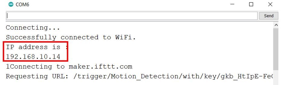
Type the IP address in a new web browser and press enter. The web server will open up. Move your hand in front of the PIR sensor and immediately the LED will turn ON. The web server will also get updated with new values.

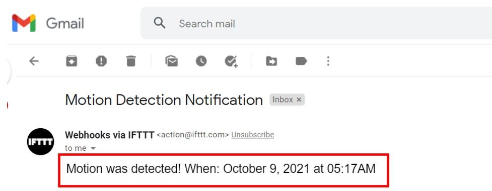
Go to your email account and open it. There you will be able to view the email notifications from IFTTT regarding the motion detection and its exact date and time.
Below is the video of the demonstration:
Conclusion
In conclusion, we were able to build an ESP8266 IoT based motion detection project using PIR sensor in Arduino IDE. We were able to create a web server that displayed motion detection with date and time and updated them in a table format. Moreover, the LED connected with the ESP8266 and the PIR sensor also turned ON in response to the sensor’s state getting HIGH (motion detected). But, you can also attach a buzzer or bell to notify someone for emergency. We also integrated IFTTT services to generate an email to us specifying the exact date and time every time a motion was detected.
You may like to read: